EP1314914A2 - Eigensichere Steuerung für ein stufenloses Getriebe - Google Patents
Eigensichere Steuerung für ein stufenloses Getriebe Download PDFInfo
- Publication number
- EP1314914A2 EP1314914A2 EP02024893A EP02024893A EP1314914A2 EP 1314914 A2 EP1314914 A2 EP 1314914A2 EP 02024893 A EP02024893 A EP 02024893A EP 02024893 A EP02024893 A EP 02024893A EP 1314914 A2 EP1314914 A2 EP 1314914A2
- Authority
- EP
- European Patent Office
- Prior art keywords
- transmission
- control system
- displacement axis
- elements
- displacement
- Prior art date
- Legal status (The legal status is an assumption and is not a legal conclusion. Google has not performed a legal analysis and makes no representation as to the accuracy of the status listed.)
- Withdrawn
Links
- 230000005540 biological transmission Effects 0.000 title claims abstract description 52
- 238000006073 displacement reaction Methods 0.000 claims abstract description 23
- 230000000875 corresponding effect Effects 0.000 claims abstract description 8
- 230000002596 correlated effect Effects 0.000 claims abstract description 4
- 230000007246 mechanism Effects 0.000 description 8
- 230000002411 adverse Effects 0.000 description 1
- 230000001276 controlling effect Effects 0.000 description 1
- 230000001419 dependent effect Effects 0.000 description 1
- 230000014509 gene expression Effects 0.000 description 1
- 238000012423 maintenance Methods 0.000 description 1
- 230000009347 mechanical transmission Effects 0.000 description 1
- 230000007935 neutral effect Effects 0.000 description 1
Images

Classifications
-
- F—MECHANICAL ENGINEERING; LIGHTING; HEATING; WEAPONS; BLASTING
- F16—ENGINEERING ELEMENTS AND UNITS; GENERAL MEASURES FOR PRODUCING AND MAINTAINING EFFECTIVE FUNCTIONING OF MACHINES OR INSTALLATIONS; THERMAL INSULATION IN GENERAL
- F16H—GEARING
- F16H61/00—Control functions within control units of change-speed- or reversing-gearings for conveying rotary motion ; Control of exclusively fluid gearing, friction gearing, gearings with endless flexible members or other particular types of gearing
- F16H61/66—Control functions within control units of change-speed- or reversing-gearings for conveying rotary motion ; Control of exclusively fluid gearing, friction gearing, gearings with endless flexible members or other particular types of gearing specially adapted for continuously variable gearings
- F16H61/664—Friction gearings
- F16H61/6648—Friction gearings controlling of shifting being influenced by a signal derived from the engine and the main coupling
-
- F—MECHANICAL ENGINEERING; LIGHTING; HEATING; WEAPONS; BLASTING
- F16—ENGINEERING ELEMENTS AND UNITS; GENERAL MEASURES FOR PRODUCING AND MAINTAINING EFFECTIVE FUNCTIONING OF MACHINES OR INSTALLATIONS; THERMAL INSULATION IN GENERAL
- F16H—GEARING
- F16H37/00—Combinations of mechanical gearings, not provided for in groups F16H1/00 - F16H35/00
- F16H37/02—Combinations of mechanical gearings, not provided for in groups F16H1/00 - F16H35/00 comprising essentially only toothed or friction gearings
- F16H37/06—Combinations of mechanical gearings, not provided for in groups F16H1/00 - F16H35/00 comprising essentially only toothed or friction gearings with a plurality of driving or driven shafts; with arrangements for dividing torque between two or more intermediate shafts
- F16H37/08—Combinations of mechanical gearings, not provided for in groups F16H1/00 - F16H35/00 comprising essentially only toothed or friction gearings with a plurality of driving or driven shafts; with arrangements for dividing torque between two or more intermediate shafts with differential gearing
- F16H37/0833—Combinations of mechanical gearings, not provided for in groups F16H1/00 - F16H35/00 comprising essentially only toothed or friction gearings with a plurality of driving or driven shafts; with arrangements for dividing torque between two or more intermediate shafts with differential gearing with arrangements for dividing torque between two or more intermediate shafts, i.e. with two or more internal power paths
- F16H37/084—Combinations of mechanical gearings, not provided for in groups F16H1/00 - F16H35/00 comprising essentially only toothed or friction gearings with a plurality of driving or driven shafts; with arrangements for dividing torque between two or more intermediate shafts with differential gearing with arrangements for dividing torque between two or more intermediate shafts, i.e. with two or more internal power paths at least one power path being a continuously variable transmission, i.e. CVT
- F16H37/0853—CVT using friction between rotary members having a first member of uniform effective diameter cooperating with different parts of a second member
Definitions
- the subject of the present invention is an intrinsically safe control system for a variable-ratio transmission, particularly of the type which is generally described by the acronym "CVT", which is derived from the term “continuously variable transmission”.
- CVT continuously variable transmission
- These transmissions enable the transmission ratio between a drive input and a drive output to be varied, preferably continuously, preferably by varying the diameter of contact between a driving element and a driven element mutually engaged for friction driving.
- Currently-known systems for controlling the variation of the transmission ratio are normally of hydraulic, mechanical or electromechanical type and are provided with electronic controls and/or torque limiters having the function of intervening in the transmission when the value of the twisting moment exceeds the safety and/or reliability threshold for the components of the transmission.
- the main task of the present invention is to provide a control system which is designed structurally and functionally to combine both the control function and the safety function of a variable-ratio transmission.
- an object of the invention is to provide an intrinsically safe control system particularly but not exclusively suitable for the operative control of a mechanical transmission with a continuously variable transmission ratio which is the subject of a patent application by the same Applicant, of the same date, and an embodiment of which is described below.
- Another object of the invention is to provide an intrinsically safe control system which at the same time is simple, reliable, and requires little or no maintenance.
- a transmission with a continuously variable transmission ratio which is the subject of a patent application of the same date in the name of the same Applicant, is generally indicated 1 in Figures 1 and 2.
- the transmission 1 is subject to the control of a transmission-ratio variation control system 100, which can vary the ratio continuously and intrinsically safely in accordance with the technical teaching offered by the present invention.
- a drive-input shaft 2 and a drive-output shaft 3 are shown in the transmission 1.
- the expressions "drive input” and “drive output” are wholly conventional since, in the transmission 1, as in many transmissions, the functions of the two shafts 2, 3 can be reversed without adversely affecting its operation.
- the shaft 2 is rotated about its axis X and a disc 4 having a friction surface 5 is fixed for rotation therewith.
- Two driven friction wheels 6a, 6b are urged against the surface 5 and can be displaced over it so as to vary the distances A, B between the respective points of contact with the surface 5 and the axis of rotation X of the shaft 2.
- the wheels 6a, 6b thus form, with the disc 4, respective disc-and-wheel continuous speed variators (in this connection, see Perucca - Dizionario di ingegneria (Dictionary of engineering) - under the headword "variatore" (variator)).
- An external preloading system ensures the friction necessary for the transmission of the drive, without slippage, between the wheels 6a, 6b and the disc 4. Since the wheels 6a, 6b lie on opposite sides of the axis X, they will be driven by being rotated by the disc 4 about their own axes at speeds proportional to the respective distances A, B from the axis X, and in opposite directions.
- the connection between the wheels 6a, 6b and the drive-output shaft 3 is formed by a differential kinematic mechanism, generally indicated 10, of the type with bevel gears.
- a differential kinematic mechanism generally indicated 10
- the use of other differentials, for example, of the epicyclic type is also envisaged.
- the total motive power input to the transmission 1 by means of the shaft 2 is split by the differential kinematic mechanism 10 along two branches (hereinafter also referred to as planetary kinematic mechanisms), each associated with one of the two wheels 6a, 6b, and recombined at the output of the differential kinematic mechanism (by an algebraic sum that takes account of the direction of rotation of the two wheels).
- the differential kinematic mechanism 10 comprises a cage 11 rotatably supporting crown wheels 12, fixed for rotation with the corresponding wheels 6a, 6b by means of respective drive-input shafts 13 and both meshing with planet gears 14.
- the crown wheels 12 adopt different speeds of rotation.
- the drive is transmitted by the planet gears 14 to the cage 11 in accordance with the drive-transmission laws characteristic of the type of differential used. Since the displacement of the two friction wheels 6a, 6b can take place continuously, the transmission ratio of the transmission 1 will also vary continuously.
- the displacements of the wheels 6a, 6b may be independent, or dependent, or only one of the friction wheels may be displaced in order to bring about the desired variation of the transmission ratio.
- the operative control of the variation of the transmission ratio is preferably performed by displacing the entire differential kinematic mechanism 10 relative to the disc and to the driven shaft 3.
- the operative control of the variation of the transmission ratio is preferably performed by displacement of the entire differential kinematic mechanism 10 relative to the disc 4 and to the driven shaft 3.
- the cage 11 is equipped with a collar 50 and the teeth of the ring gear 15 extend axially so as to be able to mesh with the pinion 16 whilst permitting an axial movement relative thereto.
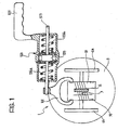
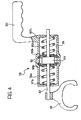
- the collar 50 houses and restrains axially a yoke 101 of the control system 100.
- the yoke 101 is fixed firmly to the end of a rod 103 guided slidably in a cylinder 104 provided with actuator means, represented schematically by a handle 105.
- the actuator means 105 enable a force for implementing the desired operative control (variation of the transmission ratio) to be applied to the cylinder 104 in the direction which tends to move the yoke 101 in corresponding manner.
- the displacement of the cylinder 104 and of the rod 103 of the yoke 101 are correlated with one another by a resilient system which comprises two springs 106a, 106b, preloaded between respective opposed shoulders 107a, 107b of the cylinder 104 and respective opposed plates 108a, 108b, between which an annular projection 109 of the rod 103 is disposed.
- the springs preferably have equal preloading and are restrained by rings 110 which act on the plates 108a, 108b so as to prevent the preloading being applied to the rod 103 when it is in the central, neutral position relative to the cylinder 104.
- the ring gear and pinion 15, 16 are a pair of spur gears or are formed by helical gears and, in any case, are such as to generate, in the presence of a torque transmitted, a thrust proportional to the twisting moment delivered by the transmission. It is desirable to keep this twisting moment below a predetermined limit, for reasons of reliability of the transmission and/or for reasons of safety.
- the displacement of the cylinder 104 by the actuator means 105 translates into a corresponding displacement of the plates 108a, 108b, if the resisting thrust on the shaft 103 is less than the preloading of the springs 106a, 106b.
- a corresponding displacement of the cage 11 and of the wheels 6a, 6b is thus brought about, with a consequent variation of the transmission ratio consistent with the above-mentioned displacement.
- the spring which is subject to this thrust yields and is compressed so that the displacement of the cylinder 104 does not lead to a corresponding variation of the transmission ratio.
- the resilient load on the shaft 103 corresponding to the resilient deformation of the spring is maintained so that, upon cessation of the transmission-overload condition, the desired variation of the transmission ratio can take place.
- the system thus permits displacement of the movable element of the transmission, with which the variation of the transmission ratio is correlated, whenever the twisting moment delivered by the transmission is below a predetermined threshold value. Whenever the twisting moment delivered by the transmission exceeds the predetermined threshold value, however, the displacement of the movable transmission element is no longer proportional to the displacement imparted by the actuator means and the value of the torque delivered is kept close to the predetermined threshold value.
- the invention thus achieves the objects proposed, affording further advantages, amongst which is effective control of the torque transmitted within the limitations of acceptability for the safety and/or reliability of the transmission. Moreover, it enables the transmission ratio to be varied gradually whilst maintaining correct control of start-up and/or temporary overload torques.
Landscapes
- Engineering & Computer Science (AREA)
- General Engineering & Computer Science (AREA)
- Mechanical Engineering (AREA)
- Control Of Transmission Device (AREA)
- Friction Gearing (AREA)
- Transmission Devices (AREA)
- Steering Control In Accordance With Driving Conditions (AREA)
- Compositions Of Oxide Ceramics (AREA)
Applications Claiming Priority (2)
| Application Number | Priority Date | Filing Date | Title |
|---|---|---|---|
| IT2001PD000274A ITPD20010274A1 (it) | 2001-11-23 | 2001-11-23 | Sistema di comando intrinsecamente sicuro per una trasmissione a rapporto variabile. |
| ITPD20010274 | 2001-11-23 |
Publications (2)
| Publication Number | Publication Date |
|---|---|
| EP1314914A2 true EP1314914A2 (de) | 2003-05-28 |
| EP1314914A3 EP1314914A3 (de) | 2005-07-20 |
Family
ID=11452485
Family Applications (1)
| Application Number | Title | Priority Date | Filing Date |
|---|---|---|---|
| EP02024893A Withdrawn EP1314914A3 (de) | 2001-11-23 | 2002-11-08 | Eigensichere Steuerung für ein stufenloses Getriebe |
Country Status (4)
| Country | Link |
|---|---|
| US (1) | US20030125159A1 (de) |
| EP (1) | EP1314914A3 (de) |
| JP (1) | JP2003185012A (de) |
| IT (1) | ITPD20010274A1 (de) |
Families Citing this family (2)
| Publication number | Priority date | Publication date | Assignee | Title |
|---|---|---|---|---|
| CN101111696B (zh) * | 2004-08-06 | 2010-09-08 | 乌尔里克·罗斯 | 具有两个相互间以一个缝隙间隔的滚动体的摩擦环传动装置 |
| CN107366732B (zh) * | 2017-07-22 | 2019-12-03 | 朱幕松 | 自动弹力变挡差速电机 |
Family Cites Families (17)
| Publication number | Priority date | Publication date | Assignee | Title |
|---|---|---|---|---|
| DE117779C (de) * | ||||
| US821631A (en) * | 1902-05-15 | 1906-05-29 | Electric Specialty Co | Car-axle gearing. |
| US1006957A (en) * | 1911-02-15 | 1911-10-24 | Albert A Lapointe | Automatic friction-wheel shifter. |
| GB191218761A (en) * | 1912-08-16 | 1913-08-07 | George Henry Denison | Improvements in Variable Speed Gearing. |
| GB122374A (en) * | 1918-09-02 | 1919-01-23 | Alfred Lewis | Improvements in Variable Velocity Ratio Transmission Gear. |
| US1384357A (en) * | 1920-11-22 | 1921-07-12 | Spencer Kelvin Tallent | Transmission-gear providing automatic compensation for variations in the speed and power transmitted |
| US1698229A (en) * | 1925-06-29 | 1929-01-08 | Frank A Hayes | Variable-speed transmission mechanism |
| FR711204A (fr) * | 1930-12-16 | 1931-09-05 | Changement de vitesse automatique | |
| FR773506A (fr) * | 1934-05-22 | 1934-11-21 | Réducteur de vitesse | |
| FR931543A (fr) * | 1946-07-30 | 1948-02-25 | Dispositif de transmission à vitesse et sens de rotation variables | |
| US2642614A (en) * | 1947-08-16 | 1953-06-23 | King Seeley Corp | Windshield wiper mechanism |
| US2850910A (en) * | 1954-03-12 | 1958-09-09 | Excelermatic | Variable speed power transmission mechanisms |
| US3464281A (en) * | 1965-10-27 | 1969-09-02 | Hiroshi Azuma | Friction-type automatic variable speed means |
| DE3037933A1 (de) * | 1980-10-08 | 1982-05-13 | Hans Heynau GmbH, 8000 München | Selbsttaetig stufenlos einstellbares schwenkgetriebe |
| US4391156A (en) * | 1980-11-10 | 1983-07-05 | William R. Loeffler | Electric motor drive with infinitely variable speed transmission |
| JP3473471B2 (ja) * | 1999-01-27 | 2003-12-02 | 日産自動車株式会社 | 変速比無限大無段変速機 |
| JP2002106665A (ja) * | 2000-10-04 | 2002-04-10 | Honda Motor Co Ltd | ダブルキャビティ・トロイダル型無段変速機 |
-
2001
- 2001-11-23 IT IT2001PD000274A patent/ITPD20010274A1/it unknown
-
2002
- 2002-11-08 EP EP02024893A patent/EP1314914A3/de not_active Withdrawn
- 2002-11-22 US US10/301,932 patent/US20030125159A1/en not_active Abandoned
- 2002-11-22 JP JP2002338857A patent/JP2003185012A/ja active Pending
Non-Patent Citations (1)
| Title |
|---|
| None |
Also Published As
| Publication number | Publication date |
|---|---|
| JP2003185012A (ja) | 2003-07-03 |
| US20030125159A1 (en) | 2003-07-03 |
| EP1314914A3 (de) | 2005-07-20 |
| ITPD20010274A1 (it) | 2003-05-23 |
Similar Documents
| Publication | Publication Date | Title |
|---|---|---|
| US5385514A (en) | High ratio planetary transmission | |
| EP0063432B1 (de) | Gesteuertes Ausgleichgetriebe | |
| EP2397723A1 (de) | Kontinuierlich variabler getriebemechanismus und getriebekasten mit dem kontinuierlich variablen getriebemechanismus | |
| RU96115190A (ru) | Бесступенчатая трансмиссия с возможностью управления крутящим моментом | |
| EP0416492B1 (de) | Stufenloses Getriebe | |
| US5232416A (en) | Method and device for the variation of locking rates | |
| CN112997025B (zh) | 行星齿轮系、齿轮箱和工业机器人 | |
| US20030125159A1 (en) | Intrinsically safe control system for a variable-ratio transmission | |
| US4409862A (en) | Variable speed rotary power transmission | |
| AU762318B2 (en) | Multiple speed orbital transmission | |
| US20030125155A1 (en) | Variable-ratio transmission | |
| US4487090A (en) | Friction drive transmission | |
| RU2304735C1 (ru) | Преобразователь передаточного отношения, зависящий от нагрузки на валу | |
| JPH04296251A (ja) | 摩擦車式無段変速機の変速制御装置 | |
| RU2550928C2 (ru) | Планетарно лобовой вариатор | |
| JPH07117133B2 (ja) | Vベルト式無段変速機 | |
| WO2017151568A1 (en) | Shift actuator system and method for a continuously variable ball planetary transmission having a rotating and/or grounded carrier | |
| US2229338A (en) | Gearing device | |
| SU1618966A1 (ru) | Привод перемещений рабочих органов металлорежущих станков | |
| US4805489A (en) | Infinitely variable ratio transmission | |
| RU1785918C (ru) | Устройство бесступенчатого фрикционного механизма передачи | |
| US3505893A (en) | Multiple speed internal gear transmission | |
| SU1055916A1 (ru) | Муфта предельного момента | |
| CN115978187A (zh) | 一种无级变速器 | |
| SU925618A1 (ru) | Устройство двухскоростного предельного резьбоверта |
Legal Events
| Date | Code | Title | Description |
|---|---|---|---|
| PUAI | Public reference made under article 153(3) epc to a published international application that has entered the european phase |
Free format text: ORIGINAL CODE: 0009012 |
|
| AK | Designated contracting states |
Designated state(s): AT BE BG CH CY CZ DE DK EE ES FI FR GB GR IE IT LI LU MC NL PT SE SK TR |
|
| AX | Request for extension of the european patent |
Extension state: AL LT LV MK RO SI |
|
| PUAL | Search report despatched |
Free format text: ORIGINAL CODE: 0009013 |
|
| AK | Designated contracting states |
Kind code of ref document: A3 Designated state(s): AT BE BG CH CY CZ DE DK EE ES FI FR GB GR IE IT LI LU MC NL PT SE SK TR |
|
| AX | Request for extension of the european patent |
Extension state: AL LT LV MK RO SI |
|
| RIC1 | Information provided on ipc code assigned before grant |
Ipc: 7F 16H 37/08 A |
|
| AKX | Designation fees paid | ||
| REG | Reference to a national code |
Ref country code: DE Ref legal event code: 8566 |
|
| STAA | Information on the status of an ep patent application or granted ep patent |
Free format text: STATUS: THE APPLICATION IS DEEMED TO BE WITHDRAWN |
|
| 18D | Application deemed to be withdrawn |
Effective date: 20060121 |