EP1314947A2 - Wärmetauscher, insbesondere für Heizungsanlagen - Google Patents
Wärmetauscher, insbesondere für Heizungsanlagen Download PDFInfo
- Publication number
- EP1314947A2 EP1314947A2 EP02025786A EP02025786A EP1314947A2 EP 1314947 A2 EP1314947 A2 EP 1314947A2 EP 02025786 A EP02025786 A EP 02025786A EP 02025786 A EP02025786 A EP 02025786A EP 1314947 A2 EP1314947 A2 EP 1314947A2
- Authority
- EP
- European Patent Office
- Prior art keywords
- heat exchanger
- different
- exchanger according
- hose
- pipeline
- Prior art date
- Legal status (The legal status is an assumption and is not a legal conclusion. Google has not performed a legal analysis and makes no representation as to the accuracy of the status listed.)
- Granted
Links
Images

Classifications
-
- F—MECHANICAL ENGINEERING; LIGHTING; HEATING; WEAPONS; BLASTING
- F24—HEATING; RANGES; VENTILATING
- F24H—FLUID HEATERS, e.g. WATER OR AIR HEATERS, HAVING HEAT-GENERATING MEANS, e.g. HEAT PUMPS, IN GENERAL
- F24H1/00—Water heaters, e.g. boilers, continuous-flow heaters or water-storage heaters
- F24H1/22—Water heaters other than continuous-flow or water-storage heaters, e.g. water heaters for central heating
- F24H1/40—Water heaters other than continuous-flow or water-storage heaters, e.g. water heaters for central heating with water tube or tubes
- F24H1/43—Water heaters other than continuous-flow or water-storage heaters, e.g. water heaters for central heating with water tube or tubes helically or spirally coiled
-
- F—MECHANICAL ENGINEERING; LIGHTING; HEATING; WEAPONS; BLASTING
- F28—HEAT EXCHANGE IN GENERAL
- F28D—HEAT-EXCHANGE APPARATUS, NOT PROVIDED FOR IN ANOTHER SUBCLASS, IN WHICH THE HEAT-EXCHANGE MEDIA DO NOT COME INTO DIRECT CONTACT
- F28D7/00—Heat-exchange apparatus having stationary tubular conduit assemblies for both heat-exchange media, the media being in contact with different sides of a conduit wall
- F28D7/02—Heat-exchange apparatus having stationary tubular conduit assemblies for both heat-exchange media, the media being in contact with different sides of a conduit wall the conduits being helically coiled
- F28D7/024—Heat-exchange apparatus having stationary tubular conduit assemblies for both heat-exchange media, the media being in contact with different sides of a conduit wall the conduits being helically coiled the conduits of only one medium being helically coiled tubes, the coils having a cylindrical configuration
-
- F—MECHANICAL ENGINEERING; LIGHTING; HEATING; WEAPONS; BLASTING
- F28—HEAT EXCHANGE IN GENERAL
- F28F—DETAILS OF HEAT-EXCHANGE AND HEAT-TRANSFER APPARATUS, OF GENERAL APPLICATION
- F28F1/00—Tubular elements; Assemblies of tubular elements
- F28F1/006—Tubular elements; Assemblies of tubular elements with variable shape, e.g. with modified tube ends, with different geometrical features
-
- F—MECHANICAL ENGINEERING; LIGHTING; HEATING; WEAPONS; BLASTING
- F28—HEAT EXCHANGE IN GENERAL
- F28F—DETAILS OF HEAT-EXCHANGE AND HEAT-TRANSFER APPARATUS, OF GENERAL APPLICATION
- F28F1/00—Tubular elements; Assemblies of tubular elements
- F28F1/08—Tubular elements crimped or corrugated in longitudinal section
Definitions
- the invention relates to a heat exchanger, in particular for heating systems, consisting of a particular cylindrical housing and one in the Housing pipeline laid, the pipeline from a corrugated hose is constructed.
- cast aluminum housings are used for use in heating systems Heat exchanger application that has an integrated burner area
- Heat exchanger application that has an integrated burner area
- Newer designs of exhaust gas heat exchangers consist of a cylindrical housing with a vertically arranged smooth tube or corrugated hose coil. At the top With this design, the area of the housing is the burner within the Corrugated hose coil arranged, the exhaust gas flowing from top to bottom and the flame of the burner directed sideways and downwards accordingly are.
- the medium to be heated flows, i.e. the water inside the corrugated hose coil from bottom to top.
- the warming of the Water takes place in such a way that in the upper area by forced convection and radiation heat is transferred from the exhaust gas to the water and that in the lower area forced convection and condensation for heat transfer to lead.
- the condensate from the condensation runs out at the bottom the heat exchanger housing.
- the present invention is based on the object Heat exchanger of the type mentioned with improved performance properties such as exchanger performance, susceptibility to failure etc.
- the hose corrugation in the upper, overheating-critical hot area quasi slightly approach a smooth tube coil, which leads to the desired favorable flow conditions and thus to avoid local overheating leads in this area.
- the wide corrugation avoids in the Wavy valleys the appearance of secondary vortices that heat transfer would hinder.
- a wide corrugation increases the diameter the detached vertebrae on the principle of the Kärmänschen vortex street and thus also contributes to the improvement of heat transfer.
- the line section provided in the lower condensation area with narrower hose corrugation, shorter wavelength and in particular steeper Wave flanks in turn have the desired maximum surface area, that in a preferred application is 2.5 times higher than one comparable smooth tube.
- the vortex or flow conditions mentioned above are in the condensation area due to the lower prevailing there Temperatures are not critical.
- the pipeline is designed as a helix and is thus helical in the heat exchanger housing laid.
- the hose and / or shaft geometries can be used for optimization the respective heat transfer properties, in particular the following Parameters vary: corrugated hose diameter, hose geometries such as wall thickness or or wave geometry such as wavelength and wave height. About that the material can also be adjusted.
- the present invention can not only be use in the example heat exchangers for heating systems, but also with any other heat exchangers, the areas with different conditions such as temperatures, heat radiation, etc.
- the line points according to the invention at least two line sections with different hose and / or Shaft geometries, namely preferably with a line section further hose corrugation and longer wavelength, in particular with flatter ones Wave flanks and a section with narrower tube corrugation of smaller wavelength and with steeper wave flanks.
- the wide hose corrugation with flat Shaft flanks are provided in a similar way to a smooth tube coil, in heat exchanger areas to be laid at high temperatures because of the wide corrugation ensures that no gas bubbles settle on the inside wall of the pipe can, which would impair the heat dissipation.
- the line section with narrower hose corrugation is suitable for such areas, the largest possible surface to optimize the heat exchanger surface have without it in the narrowly corrugated areas of the troughs or wave peaks come to critical flow or temperature influences.
- the two differently designed line sections can - depending on Use case - seamlessly merge or one - possibly also with a different geometry - Transition area to be connected.
- the heat exchanger 1 according to the invention shown in Figure 1 consists of a cylindrical housing 2 with vertical housing axis. Is in the housing a corrugated hose coil 3 also arranged with a vertical coil axis, the corrugated hose is laid so that the spiral diameter is as possible turns out large, i.e. the corrugated hose is laid along the inside of the housing is.
- the corrugated hose coil 3 has one arranged in the housing base 4 vertically oriented inlet 5 and one below the housing cover 6 arranged and extending in the horizontal direction outlet 7. Accordingly, the medium to be heated flows - that is, in the present case Water to be heated - from bottom to top through the heat exchanger.
- the medium to be heated flows from the colder lower region of the Heat exchanger in the hotter upper area.
- the burner 8 is designed that it starts from the housing cover 6 in the vertical direction downwards protrudes into the heat exchanger and the flames in particular in the horizontal direction directed radially outwards on the corrugated hose coil 3, so that in this at the level of the burner so-called hot area A des Heat exchangers heat by forced convection and by radiation on the corrugated hose and thus the medium flowing through the corrugated hose is transmitted.
- the corrugated hose is exposed to the hot air or hot exhaust gas, which the heat exchanger on the bottom by a arranged in the bottom Exhaust gas outlet 9 leaves, acted on, so that the heat is forced by Convection and condensation is transmitted.
- the Corrugated hose coil 3 In the lower condensation area B of the heat exchanger 1 is within the Corrugated hose coil 3 arranged a cylindrical displacement body 11, which blocks the interior within the coil 3 and thus the gas flow over the outside of the housing and past the corrugated hose coil 3 directed. This is how the heat exchange between the heating gas is as efficient as possible and the heating water to be heated.
- this displacement body 11 Serves at the same time this displacement body 11, the corrugated hose coil 3 on the housing wall leaving an annular gap, this annular gap as far as possible between the housing wall and the displacement body of the corrugated hose is filled in with its outer brim, i.e. the wave crests rests on the displacer and the housing wall, while the area Between two wave crests there is space for the hot exhaust gas to flow through leaves.
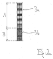
- Figure 2 shows a short section of the Corrugated hose coil in a representation developed in the plane: there is to recognize the wide corrugated line section 3a, which is assigned to the hot region A. is, while the narrowly corrugated portion 3b is the condensation area B is assigned.
- both sections go in one piece and seamlessly into each other, i.e. the continuous corrugated hose is provided with different curls.
- the present invention offers the advantage of a heat exchanger, which is built up in the usual way, but which is simple replacement of the line component is optimized such that the Pipe component to the respective conditions in the individual heat exchanger sections adapted and accordingly with a different hose and / or Shaft geometry is provided.
- This can advantageously be used to increase the size of the same size Achieve performance of the heat exchanger or with the same exchanger performance get along with smaller dimensions.
Landscapes
- Engineering & Computer Science (AREA)
- Physics & Mathematics (AREA)
- Thermal Sciences (AREA)
- Mechanical Engineering (AREA)
- General Engineering & Computer Science (AREA)
- Geometry (AREA)
- Chemical & Material Sciences (AREA)
- Combustion & Propulsion (AREA)
- Heat-Exchange Devices With Radiators And Conduit Assemblies (AREA)
Abstract
Description
- Figur 1
- einen erfindungsgemäßen Wärmetauscher im Längsschnitt; und
- Figur 2
- einen Ausschnitt des abgewickelten Metallschlauchs des erfindungsgemäßen Wärmetauschers aus Figur 1.
Claims (12)
- Wärmetauscher, insbesondere für Heizungsanlagen, bestehend aus einem insbesondere zylindrischen Gehäuse (2) und einer in dem Gehäuse verlegten Rohrleitung (3), wobei die Rohrleitung als Wellschlauch ausgebildet ist,
dadurch gekennzeichnet, dass die Rohrleitung (3) zur Optimierung der Gebrauchs- und/oder Wärmeübertragungseigenschaften in verschiedenen Bereichen (A, B) innerhalb des Wärmetauschergehäuses (2) Leitungsabschnitte (3a, 3b) mit unterschiedlich ausgeprägten und an die in den jeweiligen Bereichen vorherrschenden Verhältnisse angepassten Bauformen aufweist. - Wärmetauscher nach Anspruch 1,
dadurch gekennzeichnet, dass die Leitungsabschnitte mit unterschiedlichen Bauformen unterschiedliche Schlauch- und/oder Wellengeometrien und/oder Materialien aufweisen. - Wärmetauscher nach Anspruch 1,
dadurch gekennzeichnet, dass die Rohrleitung (3) als Wendel ausgebildet ist. - Wärmetauscher nach Anspruch 1,
dadurch gekennzeichnet, dass die Rohrleitung (3) zumindest zwei Leitungsabschnitte (3a, 3b) mit unterschiedlichen Wellengeometrien aufweist, nämlich einen Leitungsabschnitt (3a) mit weiterer Schlauchwellung und größerer Wellenlänge und einen Leitungsabschnitt (3b) mit engerer Schlauchwellung und kleinerer Wellenlänge. - Wärmetauscher nach zumindest Anspruch 1,
dadurch gekennzeichnet, dass das Wärmetauschergehäuse (2) in vertikaler Orientierung mit vertikaler Zylinderachse vorgesehen ist, und dass der Wärmetauscher (1) zumindest zwei übereinander angeordnete Bereiche (A, B) mit verschiedenen Wärmeübertragungsverhältnissen aufweist. - Wärmetauscher nach zumindest Anspruch 5,
dadurch gekennzeichnet, dass die zumindest zwei übereinander angeordneten Bereiche (A, B) aus einem Heißbereich (A) mit Wärmeübertragung durch erzwungene Konvektion und Strahlung und einem Kondensationsbereich (B) mit Wärmeübertragung durch erzwungene Konvektion und Kondensation bestehen. - Wärmetauscher nach zumindest Anspruch 6 und Anspruch 3,
dadurch gekennzeichnet, dass sich die wendelförmige Rohrleitung (3) ausgehend vom oberen Heißbereich (A) in den unteren Kondensationsbereich (B) erstreckt, und dass die wendelförmige Rohrleitung im oberen Heißbereich mit einer weiteren Schlauchwellung mit flacheren Wellenflanken als im unteren Kondensationsbereich versehen ist. - Wärmetauscher nach zumindest Anspruch 4,
dadurch gekennzeichnet, dass die zumindest zwei Leitungsabschnitte (3a, 3b) mit unterschiedlichen Wellengeometrien einstückig miteinander verbunden sind und ineinander übergehen. - Wärmetauscher nach zumindest Anspruch 4,
dadurch gekennzeichnet, dass die zumindest zwei Leitungsabschnitte (3 a, 3 b) mit unterschiedlichen Wellengeometrien jeweils verschiedenen Wellschläuchen zugeordnet sind, und
dass die zumindest zwei Wellschläuche durch Fügen zu der wendelförmigen Rohrleitung verbunden sind. - Wärmetauscher nachzumindest Anspruch 1,
dadurch gekennzeichnet, dass die Rohrleitung zumindest zwei Leitungsabschnitte mit unterschiedlichen Schlauchgeometrien wie insbesondere unterschiedlichen Innendurchmessern und/oder Wanddicken aufweist. - Wärmetauscher nach zumindest Anspruch 1,
dadurch gekennzeichnet, dass die Rohrleitung zumindest zwei aus unterschiedlichen Materialien hergestellte Leitungsabschnitte aufweist. - Wärmetauscher nach Anspruch 1,
dadurch gekennzeichnet, dass die Rohrleitung zumindest zwei Leitungsabschnitte mit unterschiedlicher Wellenhöhe aufweist.
Applications Claiming Priority (2)
| Application Number | Priority Date | Filing Date | Title |
|---|---|---|---|
| DE2001157267 DE10157267A1 (de) | 2001-11-22 | 2001-11-22 | Wärmetauscher, insbesondere für Heizungsanlagen |
| DE10157267 | 2001-11-22 |
Publications (3)
| Publication Number | Publication Date |
|---|---|
| EP1314947A2 true EP1314947A2 (de) | 2003-05-28 |
| EP1314947A3 EP1314947A3 (de) | 2004-12-15 |
| EP1314947B1 EP1314947B1 (de) | 2006-04-26 |
Family
ID=7706551
Family Applications (1)
| Application Number | Title | Priority Date | Filing Date |
|---|---|---|---|
| EP20020025786 Expired - Lifetime EP1314947B1 (de) | 2001-11-22 | 2002-11-16 | Wärmetauscher, insbesondere für Heizungsanlagen |
Country Status (2)
| Country | Link |
|---|---|
| EP (1) | EP1314947B1 (de) |
| DE (2) | DE10157267A1 (de) |
Cited By (4)
| Publication number | Priority date | Publication date | Assignee | Title |
|---|---|---|---|---|
| US6789615B2 (en) * | 2002-02-28 | 2004-09-14 | Witzenmann Gmbh | Heat exchanger, in particular for swimming pools |
| WO2007014617A1 (de) * | 2005-07-29 | 2007-02-08 | Linde Aktiengesellschaft | Gewickelter wärmetauscher mit unterschiedlichen materialien |
| WO2015160498A3 (en) * | 2014-04-15 | 2016-03-24 | Ecr International, Inc. | Heat exchanger |
| WO2022029353A1 (es) * | 2020-08-07 | 2022-02-10 | Hydronik Soluciones Tecnicas Sl | Interacumulador instantaneo de fluidos para consumo humano y/o fluidos alimenticios |
Families Citing this family (3)
| Publication number | Priority date | Publication date | Assignee | Title |
|---|---|---|---|---|
| DE10306699A1 (de) * | 2003-02-18 | 2004-09-02 | Robert Bosch Gmbh | Wärmetauscher mit einem strömungsoptimierten wärmeaufnehmenden Strömungskanal, insbesondere für ein Heizgerät |
| RU193295U1 (ru) * | 2019-06-20 | 2019-10-22 | Ришат Сафуанович Шаймухаметов | Котел водогрейный |
| EP4726310A1 (de) * | 2024-10-08 | 2026-04-15 | Metro Therm A/S | Wärmetauscher und verfahren zur herstellung des wärmetauschers |
Family Cites Families (9)
| Publication number | Priority date | Publication date | Assignee | Title |
|---|---|---|---|---|
| GB684602A (en) * | 1948-08-04 | 1952-12-24 | Giovanni Rossi | Improvements in tubular heat exchanger elements, particularly for steam boilers |
| NL8403236A (nl) * | 1984-10-24 | 1986-05-16 | Henk Durieux | Verwarmingsketel voor een centrale verwarmingsinstallatie. |
| DE4110264A1 (de) * | 1990-06-28 | 1992-01-02 | Witzenmann Metallschlauchfab | Waermetauscher, insbesondere kraftstoffkuehler fuer eine verbrennungskraftmaschine |
| US5131351A (en) * | 1991-08-05 | 1992-07-21 | Farina Alfred J | Heat exchanger plug |
| US5782208A (en) * | 1994-06-15 | 1998-07-21 | Glowcore Acquisition Company | Water boiler with metal core |
| US5572885A (en) * | 1995-06-06 | 1996-11-12 | Erickson; Donald C. | Shrouded coiled crested tube diabatic mass exchanger |
| DE19529559A1 (de) * | 1995-08-11 | 1997-02-13 | Wieland Werke Ag | Wärmeaustauschsystem zur Wassererwärmung |
| AT409546B (de) * | 1998-12-17 | 2002-09-25 | Vaillant Gmbh | Wasserheizgerät |
| DE20100116U1 (de) * | 2001-01-05 | 2001-03-22 | hde Metallwerk GmbH, 58706 Menden | Wärmetauscherrohr für flüssige oder gasförmige Medien |
-
2001
- 2001-11-22 DE DE2001157267 patent/DE10157267A1/de not_active Ceased
-
2002
- 2002-11-16 EP EP20020025786 patent/EP1314947B1/de not_active Expired - Lifetime
- 2002-11-16 DE DE50206542T patent/DE50206542D1/de not_active Expired - Lifetime
Cited By (8)
| Publication number | Priority date | Publication date | Assignee | Title |
|---|---|---|---|---|
| US6789615B2 (en) * | 2002-02-28 | 2004-09-14 | Witzenmann Gmbh | Heat exchanger, in particular for swimming pools |
| WO2007014617A1 (de) * | 2005-07-29 | 2007-02-08 | Linde Aktiengesellschaft | Gewickelter wärmetauscher mit unterschiedlichen materialien |
| CN101233379B (zh) * | 2005-07-29 | 2010-09-01 | 林德股份公司 | 具有不同材料的缠绕式换热器 |
| US8297074B2 (en) | 2005-07-29 | 2012-10-30 | Linde Aktiengesellschaft | Coiled heat exchanger having different materials |
| WO2015160498A3 (en) * | 2014-04-15 | 2016-03-24 | Ecr International, Inc. | Heat exchanger |
| US10012413B2 (en) | 2014-04-15 | 2018-07-03 | Ecr International, Inc. | Heat exchanger |
| WO2022029353A1 (es) * | 2020-08-07 | 2022-02-10 | Hydronik Soluciones Tecnicas Sl | Interacumulador instantaneo de fluidos para consumo humano y/o fluidos alimenticios |
| ES2894175A1 (es) * | 2020-08-07 | 2022-02-11 | Hydronik Soluciones Tecn Sl | Interacumulador instantaneo de fluidos para consumo humano y/o fluidos alimenticios |
Also Published As
| Publication number | Publication date |
|---|---|
| EP1314947B1 (de) | 2006-04-26 |
| DE10157267A1 (de) | 2003-06-12 |
| DE50206542D1 (de) | 2006-06-01 |
| EP1314947A3 (de) | 2004-12-15 |
Similar Documents
| Publication | Publication Date | Title |
|---|---|---|
| EP0544853A1 (de) | Luftheizgerät. | |
| DE102016006913B4 (de) | Wärmeübertragerrohr | |
| DE102010008175B4 (de) | Wärmeübertrager | |
| EP1314947B1 (de) | Wärmetauscher, insbesondere für Heizungsanlagen | |
| EP0758731B1 (de) | Wärmeaustauschsystem zur Wasserwärmung | |
| DE1601240A1 (de) | Mit Rippen versehener Waermeaustauscher | |
| EP1899654B1 (de) | Heizkessel | |
| EP1770250B1 (de) | Wärmetauscher für Abgasleitungen | |
| EP0745813A2 (de) | Wärmeübertrager, insbesondere für einen Heizkessel | |
| EP2157382A2 (de) | Heizgerät | |
| EP0767888B2 (de) | Vorrichtung zum erwärmen von brauchwasser | |
| EP0497113B1 (de) | Wärmetauscher zur Warmwassererzeugung mit Öl- oder Gasbrennern | |
| EP1703227B1 (de) | Wärmetauscher | |
| EP1340953B1 (de) | Wärmetauscher, insbesondere für Schwimmbäder | |
| DE10002894B4 (de) | Wasserheizer | |
| EP1439354B1 (de) | Wärmeaustauscher | |
| DE102012008183B4 (de) | Wärmetauscherbausatz | |
| DE3519315A1 (de) | Waermetauscher aus einem huellrohr und einem im innern des huellrohres angeordneten wendelartig verlaufenden rohr | |
| DE102014015508B4 (de) | Wärmetauscherbausatz | |
| DE10212491B4 (de) | Rippenrohr mit inneren Vorsprüngen | |
| EP1888992B1 (de) | Heizkörper | |
| DE19537210C2 (de) | Wärmetauscherelement | |
| EP0583574A1 (de) | Gasheizkessel | |
| EP1396688A2 (de) | Wärmeübertrager für brennstoffbeheizte Wassererhitzer | |
| AT517854B1 (de) | Wärmeübertrager |
Legal Events
| Date | Code | Title | Description |
|---|---|---|---|
| PUAI | Public reference made under article 153(3) epc to a published international application that has entered the european phase |
Free format text: ORIGINAL CODE: 0009012 |
|
| AK | Designated contracting states |
Designated state(s): AT BE BG CH CY CZ DE DK EE ES FI FR GB GR IE IT LI LU MC NL PT SE SK TR |
|
| AX | Request for extension of the european patent |
Extension state: AL LT LV MK RO SI |
|
| PUAL | Search report despatched |
Free format text: ORIGINAL CODE: 0009013 |
|
| AK | Designated contracting states |
Kind code of ref document: A3 Designated state(s): AT BE BG CH CY CZ DE DK EE ES FI FR GB GR IE IT LI LU MC NL PT SE SK TR |
|
| AX | Request for extension of the european patent |
Extension state: AL LT LV MK RO SI |
|
| 17P | Request for examination filed |
Effective date: 20050426 |
|
| AKX | Designation fees paid |
Designated state(s): DE IT NL |
|
| GRAP | Despatch of communication of intention to grant a patent |
Free format text: ORIGINAL CODE: EPIDOSNIGR1 |
|
| GRAS | Grant fee paid |
Free format text: ORIGINAL CODE: EPIDOSNIGR3 |
|
| GRAA | (expected) grant |
Free format text: ORIGINAL CODE: 0009210 |
|
| AK | Designated contracting states |
Kind code of ref document: B1 Designated state(s): DE IT NL |
|
| PG25 | Lapsed in a contracting state [announced via postgrant information from national office to epo] |
Ref country code: IT Free format text: LAPSE BECAUSE OF FAILURE TO SUBMIT A TRANSLATION OF THE DESCRIPTION OR TO PAY THE FEE WITHIN THE PRESCRIBED TIME-LIMIT;WARNING: LAPSES OF ITALIAN PATENTS WITH EFFECTIVE DATE BEFORE 2007 MAY HAVE OCCURRED AT ANY TIME BEFORE 2007. THE CORRECT EFFECTIVE DATE MAY BE DIFFERENT FROM THE ONE RECORDED. Effective date: 20060426 |
|
| REF | Corresponds to: |
Ref document number: 50206542 Country of ref document: DE Date of ref document: 20060601 Kind code of ref document: P |
|
| PLBE | No opposition filed within time limit |
Free format text: ORIGINAL CODE: 0009261 |
|
| STAA | Information on the status of an ep patent application or granted ep patent |
Free format text: STATUS: NO OPPOSITION FILED WITHIN TIME LIMIT |
|
| 26N | No opposition filed |
Effective date: 20070129 |
|
| PGFP | Annual fee paid to national office [announced via postgrant information from national office to epo] |
Ref country code: NL Payment date: 20091123 Year of fee payment: 8 |
|
| PGFP | Annual fee paid to national office [announced via postgrant information from national office to epo] |
Ref country code: IT Payment date: 20091130 Year of fee payment: 8 |
|
| PGFP | Annual fee paid to national office [announced via postgrant information from national office to epo] |
Ref country code: DE Payment date: 20101126 Year of fee payment: 9 |
|
| REG | Reference to a national code |
Ref country code: NL Ref legal event code: V1 Effective date: 20110601 |
|
| PG25 | Lapsed in a contracting state [announced via postgrant information from national office to epo] |
Ref country code: NL Free format text: LAPSE BECAUSE OF NON-PAYMENT OF DUE FEES Effective date: 20110601 |
|
| PG25 | Lapsed in a contracting state [announced via postgrant information from national office to epo] |
Ref country code: IT Free format text: LAPSE BECAUSE OF NON-PAYMENT OF DUE FEES Effective date: 20101116 |
|
| REG | Reference to a national code |
Ref country code: DE Ref legal event code: R119 Ref document number: 50206542 Country of ref document: DE Effective date: 20120601 |
|
| PG25 | Lapsed in a contracting state [announced via postgrant information from national office to epo] |
Ref country code: DE Free format text: LAPSE BECAUSE OF NON-PAYMENT OF DUE FEES Effective date: 20120601 |