EP1315010A2 - Lichtwellenleiter-Endverschluss - Google Patents
Lichtwellenleiter-Endverschluss Download PDFInfo
- Publication number
- EP1315010A2 EP1315010A2 EP02360307A EP02360307A EP1315010A2 EP 1315010 A2 EP1315010 A2 EP 1315010A2 EP 02360307 A EP02360307 A EP 02360307A EP 02360307 A EP02360307 A EP 02360307A EP 1315010 A2 EP1315010 A2 EP 1315010A2
- Authority
- EP
- European Patent Office
- Prior art keywords
- optical
- cable
- end closure
- head fitting
- fitting
- Prior art date
- Legal status (The legal status is an assumption and is not a legal conclusion. Google has not performed a legal analysis and makes no representation as to the accuracy of the status listed.)
- Granted
Links
Images

Classifications
-
- G—PHYSICS
- G02—OPTICS
- G02B—OPTICAL ELEMENTS, SYSTEMS OR APPARATUS
- G02B6/00—Light guides; Structural details of arrangements comprising light guides and other optical elements, e.g. couplings
- G02B6/44—Mechanical structures for providing tensile strength and external protection for fibres, e.g. optical transmission cables
- G02B6/4401—Optical cables
- G02B6/4415—Cables for special applications
- G02B6/4416—Heterogeneous cables
- G02B6/4417—High voltage aspects, e.g. in cladding
- G02B6/442—Insulators
Definitions
- the invention relates to an optical waveguide (fiber optic) end closure of an optical fiber phase rope according to the preamble of claim 1.
- DE 39 42 245 describes an optical fiber end closure in which the end of the phase rope is enclosed by a rope clamp and at least one Optical fiber is out of the end of the phase cable to the head fitting of the End closure insulator, further into its foot fitting and finally into one Splice housing guided.
- the optical fiber is cast in the isolator and in the Splice housing connected to a further optical fiber.
- the isolator consists of a tube made of glass fiber reinforced plastic, which from a Layer of silicone rubber is encased and several superimposed Has screens made of silicone rubber.
- the foot and head fittings are on the Flanged insulator and both have a splice housing.
- the optical fiber is from the upper splice case in turns over the pipe glass fiber reinforced plastic of the isolator led to the lower splice case.
- the interior of the insulator is filled with silicone rubber and the insulator thus trained as a supporter.
- the fiber optic end closure is completely prefabricated in the factory and needs only to be set up and connected at the construction site.
- This approach is particularly disadvantageous if more is housed as an optical fiber in the phase rope. More recently Up to 144 optical fibers are provided in a phase rope, one conductor wire is replaced by a steel tube in the phase rope. With an occupancy of the phase rope with 144 optical fibers are three tubes with 48 each To accommodate optical fibers in a phase rope. At lofty heights too adverse splicing work takes a lot of time claim and can last up to a week extend.
- the present invention has for its object the known Fiber optic termination to improve the splicing work be significantly shortened at the installation site.
- Fiber optic end closure still has the advantage that only one Splice connection per optical fiber must be carried out at lofty heights.
- the Introduction of the core or the cores of the phase cable into the foot armature and the The fiber optic connection cable is introduced into the head fitting by means of standardized cable glands. However, it also comes Multiple seals for a loose tube seal are used.
- the invention is illustrated schematically in the figure Embodiment explained in more detail.
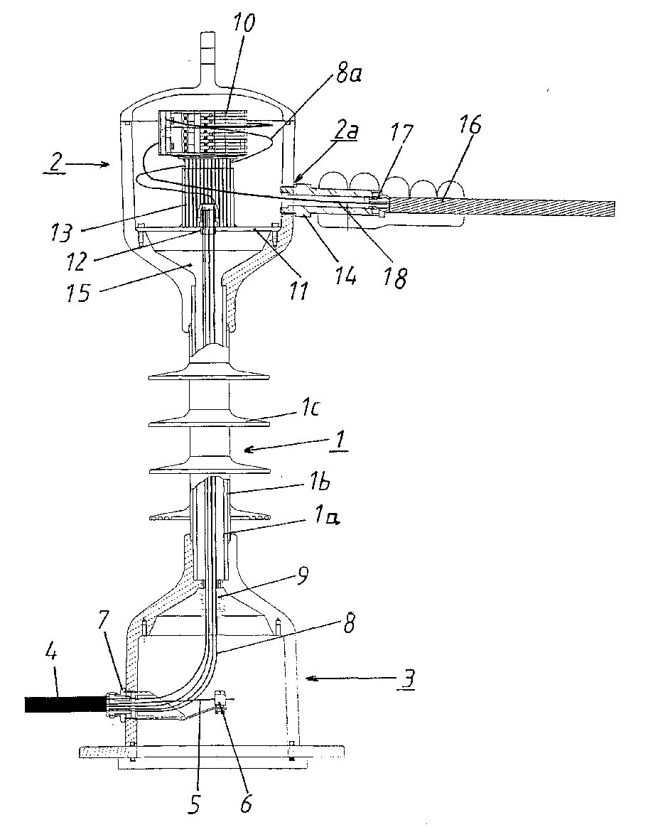
- the fiber optic end closure consists of a composite insulator 1 from a Tube 1a made of glass fiber reinforced plastic, on which a layer 1b Silicone rubber is extruded, as well as from several plate screens 1c attached to the Layer 1 b are vulcanized.
- a Head fitting 2 and a foot fitting 3 At the ends of the composite insulator 1 is a Head fitting 2 and a foot fitting 3 attached. Leave head and foot fittings are designed constructively from a few basic components for both functions.
- the foot fitting 3 serves to stand up the end closure and to introduce it and interception of a metal-free optical fiber connecting cable 4, the tensile central element 5 within the foot fitting 3, as shown at 6, is intercepted.
- the optical fiber cable 4 is replaced by a commercially available Cable gland 7 liquid-tight in the interior of the foot fitting 3 led in.
- the cores 8 - usually these are loose tubes - are through led the inside of the tube 1a through to the head fitting 2.
- Another Cable gland 9 seals the cavity of the tube 1a downwards.
- the head fitting 2 has a splicing space in its interior, which has at least one Splice cassette 10 takes.
- the splice cassette 10 is preferably designed such that that up to 144 splices can be accommodated. Cascading the Splice trays for a further expansion stage are possible.
- the interior of the head fitting 2 is designed so that the stock length 8a Veins 8 place.
- a separating plate 11 which the cavity of the tube 1a against the interior of the head fitting 2nd concludes.
- the wires 8 are liquid-tight through the partition plate 11 passed through, namely by means of a commercially available cable gland 12 with multiple seals.
- a bracket 13 is attached, at the end of which Splice trays 10 are held.
- the head fitting 2 there is an opening 2a, into which a tensile Hollow pin 14 is inserted, through which the core 18 or several cores of the Phase cable 16 is or are introduced into the interior of the head fitting 2.
- phase cable 16 to the end closure is known per se and should not be described in more detail.
- the core 18 of the phase cable 16 is usually a so-called loose tube, d. H. inside a steel tube are a variety of optical fibers z. B. 48 arranged.
- the steel loose tube 18 is liquid-tight by a cable gland 17 in the hollow pin 14 inserted.
- Compensation chamber 15 is filled with a filling compound based on silicone without bubbles.
- the cavity and the compensation chamber 15 are filled after completion the splicing work, but can also be done at the factory.
- the ends then be spliced to the ends of the optical fibers of the FO cable 4 can.
Landscapes
- Physics & Mathematics (AREA)
- General Physics & Mathematics (AREA)
- Optics & Photonics (AREA)
- Light Guides In General And Applications Therefor (AREA)
- Mechanical Coupling Of Light Guides (AREA)
- Insulators (AREA)
- Optical Couplings Of Light Guides (AREA)
- Cable Accessories (AREA)
- Glass Compositions (AREA)
- Communication Cables (AREA)
Abstract
Description
Claims (6)
- Lichtwellenleiter-Endverschluß eines LWL-Phasenseils (16), bestehend aus einem rohrförmigen Verbundisolator (1), mit einer an einem Ende angebrachten Kopfarmatur (2) und einer am entgegengesetzten Ende angebrachten Fußarmatur (3), gekennzeichnet durch folgende Merkmalea) in die Fußarmatur (3) ist ein optisches Kabel (4) flüssigkeitsdicht eingeführt,b) die Lichtwellenleiter und/oder Adern (8) des optischen Kabels (4) sind in dem Innenraum des Verbundisolators (1) zur Kopfarmatur (2) geführt,c) die Lichtwellenleiter und/oder Adern (8) liegen als Vorratslänge (8a) in der Kopfarmatur (2),d) in der Kopfarmatur (2) ist zumindest eine Spleißkassette (10) zur Aufnahme der Spleißverbindungen der optischen Fasern des optischen Kabels (4) und der optischen Fasern des Phasenseils (16) angeordnet,e) der Innenraum des Verbundisolators (1) ist mit einer flüssigen Füllmasse blasenfrei ausgefüllt.
- Lichtwellenleiter-Endverschluß nach Anspruch 1, dadurch gekennzeichnet, daß die Ader bzw. die Adern (18) des Phasenseils (16) durch eine Öffnung (2a) in der Wandung der Kopfarmatur (2) in diese flüssigkeitsdicht eingeführt ist (sind).
- Lichtwellenleiter-Endverschluß nach Anspruch 1 oder 2, dadurch gekennzeichnet, daß die Lichtwellenleiter und/oder Adern (8) des optischen Kabels (4) durch Abdichtanordnungen (9) in das Innere des Verbundisolators (1) hereingeführt und aus diesem herausgeführt sind.
- Lichtwellenleiter-Endverschluß nach einem der Ansprüche 1 bis 3, dadurch gekennzeichnet, daß in der Kopfarmatur (2) ein Ausgleichsraum (15) für die thermisch bedingte Ausdehnung der Füllmasse vorgesehen ist.
- Lichtwellenleiter-Endverschluß nach einem der Ansprüche 1 bis 4, dadurch gekennzeichnet, daß die Füllmasse ein Silikonelastomer ist.
- Lichtwellenleiter-Endverschluß nach einem der Ansprüche 1 bis 5, dadurch gekennzeichnet, daß innerhalb der Kopfarmatur (2) ein den Ausgleichsraum (15) und den Raum, in welchem sich die Spleißkassette befindet, trennendes Blech (11) vorgesehen ist, an welchem eine Halterung (13) für die Spleißkassetten (10) befestigt ist.
Applications Claiming Priority (2)
| Application Number | Priority Date | Filing Date | Title |
|---|---|---|---|
| DE10157056A DE10157056A1 (de) | 2001-11-21 | 2001-11-21 | Lichtwellenleiter-Endverschluss |
| DE10157056 | 2001-11-21 |
Publications (4)
| Publication Number | Publication Date |
|---|---|
| EP1315010A2 true EP1315010A2 (de) | 2003-05-28 |
| EP1315010A3 EP1315010A3 (de) | 2004-08-18 |
| EP1315010B1 EP1315010B1 (de) | 2009-07-29 |
| EP1315010B8 EP1315010B8 (de) | 2009-10-07 |
Family
ID=7706406
Family Applications (1)
| Application Number | Title | Priority Date | Filing Date |
|---|---|---|---|
| EP02360307A Expired - Lifetime EP1315010B8 (de) | 2001-11-21 | 2002-11-12 | Lichtwellenleiter-Endverschluss |
Country Status (4)
| Country | Link |
|---|---|
| US (1) | US6690874B2 (de) |
| EP (1) | EP1315010B8 (de) |
| AT (1) | ATE438116T1 (de) |
| DE (2) | DE10157056A1 (de) |
Families Citing this family (19)
| Publication number | Priority date | Publication date | Assignee | Title |
|---|---|---|---|---|
| US20050207711A1 (en) * | 2004-03-19 | 2005-09-22 | Vo Chanh C | Optical termination pedestal |
| US7689089B2 (en) * | 2006-10-11 | 2010-03-30 | Panduit Corp. | Release latch for pre-terminated cassette |
| US8798427B2 (en) | 2007-09-05 | 2014-08-05 | Corning Cable Systems Llc | Fiber optic terminal assembly |
| EP2344915A4 (de) | 2008-10-09 | 2015-01-21 | Corning Cable Sys Llc | Faseroptischer anschluss mit adaptertafel, die sowohl eingangs- als auch ausgangsfasern von einem optischen teiler unterstützt |
| US8879882B2 (en) | 2008-10-27 | 2014-11-04 | Corning Cable Systems Llc | Variably configurable and modular local convergence point |
| EP2237091A1 (de) | 2009-03-31 | 2010-10-06 | Corning Cable Systems LLC | Lösbar montierbares LWL-Leitungsendgerät |
| US8467651B2 (en) * | 2009-09-30 | 2013-06-18 | Ccs Technology Inc. | Fiber optic terminals configured to dispose a fiber optic connection panel(s) within an optical fiber perimeter and related methods |
| US9547144B2 (en) | 2010-03-16 | 2017-01-17 | Corning Optical Communications LLC | Fiber optic distribution network for multiple dwelling units |
| US8792767B2 (en) | 2010-04-16 | 2014-07-29 | Ccs Technology, Inc. | Distribution device |
| US9720197B2 (en) | 2010-10-19 | 2017-08-01 | Corning Optical Communications LLC | Transition box for multiple dwelling unit fiber optic distribution network |
| US8686289B2 (en) | 2011-07-14 | 2014-04-01 | Channell Commercial Corporation | Sealing mechanism and method for drop cable splice enclosures |
| CN102368602A (zh) * | 2011-11-14 | 2012-03-07 | 天津市电力公司 | 导体线芯内置测温光纤的高压电缆终端引出及密封方法 |
| US9219546B2 (en) | 2011-12-12 | 2015-12-22 | Corning Optical Communications LLC | Extremely high frequency (EHF) distributed antenna systems, and related components and methods |
| US10110307B2 (en) | 2012-03-02 | 2018-10-23 | Corning Optical Communications LLC | Optical network units (ONUs) for high bandwidth connectivity, and related components and methods |
| US9004778B2 (en) | 2012-06-29 | 2015-04-14 | Corning Cable Systems Llc | Indexable optical fiber connectors and optical fiber connector arrays |
| US9049500B2 (en) | 2012-08-31 | 2015-06-02 | Corning Cable Systems Llc | Fiber optic terminals, systems, and methods for network service management |
| US8909019B2 (en) | 2012-10-11 | 2014-12-09 | Ccs Technology, Inc. | System comprising a plurality of distribution devices and distribution device |
| CN110749963A (zh) * | 2019-11-22 | 2020-02-04 | 深圳新阳蓝光能源科技股份有限公司 | 一种光电终端接头盒防水等级的改良装置 |
| US12449622B2 (en) * | 2022-03-07 | 2025-10-21 | Verity Instruments, Inc. | Fiberoptical cable assemblies and interfaces for spectrometers |
Family Cites Families (10)
| Publication number | Priority date | Publication date | Assignee | Title |
|---|---|---|---|---|
| DE3025700C2 (de) * | 1980-07-07 | 1983-11-17 | Siemens AG, 1000 Berlin und 8000 München | Muffe für hochpaarige Lichtwellenleiter-Kabel |
| US4687289A (en) * | 1985-09-17 | 1987-08-18 | Brintec Corporation | Fiberoptic splice organizer |
| DE3841607C2 (de) * | 1988-12-08 | 1996-05-23 | Siemens Ag | Kassette für Überlängen von Lichtwellenleitern im Spleißstellenbereich |
| DE3942245A1 (de) * | 1989-12-21 | 1991-06-27 | Felten & Guilleaume Energie | Lichtwellenleiter-(lwl-)endverschluss eines lwl-phasenseils |
| US5187766A (en) * | 1991-02-27 | 1993-02-16 | Siemens Aktiengesellschaft | Optical fiber waveguide division rack for holding plural cassettes |
| JPH05325688A (ja) * | 1992-05-26 | 1993-12-10 | Furukawa Electric Co Ltd:The | 光ファイバ内蔵碍管 |
| US5218664A (en) * | 1992-05-26 | 1993-06-08 | Siecor Corporation | Splice closure with lifting handles |
| DE4242038C2 (de) * | 1992-12-12 | 1997-08-14 | Felten & Guilleaume Energie | Ankoppeleinrichtung |
| DE19955271B4 (de) * | 1999-11-17 | 2004-03-18 | Nkt Cables Gmbh | Endverschluß |
| WO2003019243A2 (en) * | 2001-05-21 | 2003-03-06 | Wave7 Optics, Inc. | Cable splice enclosure and components |
-
2001
- 2001-11-21 DE DE10157056A patent/DE10157056A1/de not_active Withdrawn
-
2002
- 2002-11-12 DE DE50213719T patent/DE50213719D1/de not_active Expired - Lifetime
- 2002-11-12 EP EP02360307A patent/EP1315010B8/de not_active Expired - Lifetime
- 2002-11-12 AT AT02360307T patent/ATE438116T1/de not_active IP Right Cessation
- 2002-11-19 US US10/298,912 patent/US6690874B2/en not_active Expired - Lifetime
Also Published As
| Publication number | Publication date |
|---|---|
| US20030095774A1 (en) | 2003-05-22 |
| DE50213719D1 (de) | 2009-09-10 |
| DE10157056A1 (de) | 2003-05-28 |
| US6690874B2 (en) | 2004-02-10 |
| EP1315010A3 (de) | 2004-08-18 |
| EP1315010B1 (de) | 2009-07-29 |
| EP1315010B8 (de) | 2009-10-07 |
| ATE438116T1 (de) | 2009-08-15 |
Similar Documents
| Publication | Publication Date | Title |
|---|---|---|
| EP1315010A2 (de) | Lichtwellenleiter-Endverschluss | |
| DE69325046T2 (de) | Hybridnachrichtenkabel zur Verbesserung der Übertragungsfähigkeit | |
| EP0265737B1 (de) | Lichtleiteranordnung bei einem Hochspannungsisolator | |
| EP0715196A1 (de) | Kassettenmodul für Lichtwellenleiter | |
| EP0087757A1 (de) | Einrichtung zur Herstellung eines elektrischen und/oder optischen Kabels | |
| EP0025229A1 (de) | Spleissverbindung von Lichtwellenleiter-Kabeln mit Hohladern | |
| DE4227410C1 (de) | Freiluft-endverschluss fuer lichtwellenleiter-phasenseile (lps). | |
| EP0433565A2 (de) | Lichtwellenleiter-(LWL)-Endverschluss eines LWL-Phasenseils | |
| CH710076B1 (de) | Rahmenvorrichtung für eine Fasermanagementeinheit. | |
| DE4012183C2 (de) | ||
| DE3118173A1 (de) | Lichtwellenleiter enthaltende, druckgasueberwachte kabelanordnung mit verbindungsmuffe | |
| DE3340972A1 (de) | Verfahren zum einbringen eines lichtwellenleiters in eine schutzhuelle | |
| DE4214039C2 (de) | Vorrichtung zum Aufteilen von Lichtwellenleitern eines optischen Kabels | |
| DE4323762C1 (de) | Aufschiebbare Verbindungsmuffe für kunststoffisolierte Mittelspannungskabel mit Lichtwellenleitern | |
| DE19601576A1 (de) | Kabelmuffe für Lichtwellenleiter mit Spleißkassetten und Überlängenablagen | |
| EP0547323B1 (de) | LWL-Verbindungseinrichtung für eine Abzweigung und Verfahren zum Herstellen einer LWL-Verbindung an einer Abzweigung | |
| DE4314520C1 (de) | Bausatz für Kabelmuffen | |
| DE9311129U1 (de) | Spleißkassette für eine Kabelgarnitur mit Lichtwellenleiterkabeln | |
| DE3732486A1 (de) | Einrichtung zum abschluss einer rohr- oder schlauchartigen kabelfuehrungseinrichtung | |
| DE3732024A1 (de) | Muffe fuer lichtwellenleiterkabel | |
| WO2002014908A2 (de) | Vorkonfektioniertes lichtwellenleiter-kabel und verfahren zur vorkonfektionierung eines lichtwellenleiter-kabels | |
| DE102005014069A1 (de) | Vorrichtung zur strukturierten Ablage bzw. Handhabung von in Mikrokabeln geführten Lichtwellenleitern | |
| DE4309538A1 (de) | Verzweigungseinrichtung | |
| DE29610075U1 (de) | Haubenmuffe für Lichtwellenleiter-Erd- oder Phasenseile | |
| DE3639237A1 (de) | Verbindungseinrichtung fuer in einer aussenhuelle untergebrachte lichtwellenleiter |
Legal Events
| Date | Code | Title | Description |
|---|---|---|---|
| PUAI | Public reference made under article 153(3) epc to a published international application that has entered the european phase |
Free format text: ORIGINAL CODE: 0009012 |
|
| AK | Designated contracting states |
Designated state(s): AT BE BG CH CY CZ DE DK EE ES FI FR GB GR IE IT LI LU MC NL PT SE SK TR |
|
| AX | Request for extension of the european patent |
Extension state: AL LT LV MK RO SI |
|
| PUAL | Search report despatched |
Free format text: ORIGINAL CODE: 0009013 |
|
| AK | Designated contracting states |
Kind code of ref document: A3 Designated state(s): AT BE BG CH CY CZ DE DK EE ES FI FR GB GR IE IT LI LU MC NL PT SE SK TR |
|
| AX | Request for extension of the european patent |
Extension state: AL LT LV MK RO SI |
|
| 17P | Request for examination filed |
Effective date: 20041126 |
|
| 17Q | First examination report despatched |
Effective date: 20050110 |
|
| AKX | Designation fees paid |
Designated state(s): AT BE BG CH CY CZ DE DK EE ES FI FR GB GR IE IT LI LU MC NL PT SE SK TR |
|
| RAP1 | Party data changed (applicant data changed or rights of an application transferred) |
Owner name: DRAKA COMTEQ B.V. |
|
| 17Q | First examination report despatched |
Effective date: 20050110 |
|
| RAP1 | Party data changed (applicant data changed or rights of an application transferred) |
Owner name: DRAKA COMTEQ B.V. |
|
| RAP1 | Party data changed (applicant data changed or rights of an application transferred) |
Owner name: DRAKA COMTEQ B.V. |
|
| GRAP | Despatch of communication of intention to grant a patent |
Free format text: ORIGINAL CODE: EPIDOSNIGR1 |
|
| GRAS | Grant fee paid |
Free format text: ORIGINAL CODE: EPIDOSNIGR3 |
|
| GRAA | (expected) grant |
Free format text: ORIGINAL CODE: 0009210 |
|
| AK | Designated contracting states |
Kind code of ref document: B1 Designated state(s): AT BE BG CH CY CZ DE DK EE ES FI FR GB GR IE IT LI LU MC NL PT SE SK TR |
|
| REG | Reference to a national code |
Ref country code: GB Ref legal event code: FG4D Free format text: NOT ENGLISH |
|
| REG | Reference to a national code |
Ref country code: CH Ref legal event code: EP |
|
| REG | Reference to a national code |
Ref country code: IE Ref legal event code: FG4D |
|
| REF | Corresponds to: |
Ref document number: 50213719 Country of ref document: DE Date of ref document: 20090910 Kind code of ref document: P |
|
| RAP2 | Party data changed (patent owner data changed or rights of a patent transferred) |
Owner name: AFL TELECOMMUNICATIONS GMBH |
|
| NLT2 | Nl: modifications (of names), taken from the european patent patent bulletin |
Owner name: AFL TELECOMMUNICATIONS GMBH Effective date: 20090916 |
|
| NLV1 | Nl: lapsed or annulled due to failure to fulfill the requirements of art. 29p and 29m of the patents act | ||
| PG25 | Lapsed in a contracting state [announced via postgrant information from national office to epo] |
Ref country code: ES Free format text: LAPSE BECAUSE OF FAILURE TO SUBMIT A TRANSLATION OF THE DESCRIPTION OR TO PAY THE FEE WITHIN THE PRESCRIBED TIME-LIMIT Effective date: 20091109 Ref country code: SE Free format text: LAPSE BECAUSE OF FAILURE TO SUBMIT A TRANSLATION OF THE DESCRIPTION OR TO PAY THE FEE WITHIN THE PRESCRIBED TIME-LIMIT Effective date: 20090729 Ref country code: FI Free format text: LAPSE BECAUSE OF FAILURE TO SUBMIT A TRANSLATION OF THE DESCRIPTION OR TO PAY THE FEE WITHIN THE PRESCRIBED TIME-LIMIT Effective date: 20090729 |
|
| PG25 | Lapsed in a contracting state [announced via postgrant information from national office to epo] |
Ref country code: NL Free format text: LAPSE BECAUSE OF FAILURE TO SUBMIT A TRANSLATION OF THE DESCRIPTION OR TO PAY THE FEE WITHIN THE PRESCRIBED TIME-LIMIT Effective date: 20090729 |
|
| REG | Reference to a national code |
Ref country code: IE Ref legal event code: FD4D |
|
| PG25 | Lapsed in a contracting state [announced via postgrant information from national office to epo] |
Ref country code: PT Free format text: LAPSE BECAUSE OF FAILURE TO SUBMIT A TRANSLATION OF THE DESCRIPTION OR TO PAY THE FEE WITHIN THE PRESCRIBED TIME-LIMIT Effective date: 20091129 Ref country code: BG Free format text: LAPSE BECAUSE OF FAILURE TO SUBMIT A TRANSLATION OF THE DESCRIPTION OR TO PAY THE FEE WITHIN THE PRESCRIBED TIME-LIMIT Effective date: 20091029 |
|
| PG25 | Lapsed in a contracting state [announced via postgrant information from national office to epo] |
Ref country code: DK Free format text: LAPSE BECAUSE OF FAILURE TO SUBMIT A TRANSLATION OF THE DESCRIPTION OR TO PAY THE FEE WITHIN THE PRESCRIBED TIME-LIMIT Effective date: 20090729 Ref country code: EE Free format text: LAPSE BECAUSE OF FAILURE TO SUBMIT A TRANSLATION OF THE DESCRIPTION OR TO PAY THE FEE WITHIN THE PRESCRIBED TIME-LIMIT Effective date: 20090729 Ref country code: IE Free format text: LAPSE BECAUSE OF FAILURE TO SUBMIT A TRANSLATION OF THE DESCRIPTION OR TO PAY THE FEE WITHIN THE PRESCRIBED TIME-LIMIT Effective date: 20090729 Ref country code: CZ Free format text: LAPSE BECAUSE OF FAILURE TO SUBMIT A TRANSLATION OF THE DESCRIPTION OR TO PAY THE FEE WITHIN THE PRESCRIBED TIME-LIMIT Effective date: 20090729 |
|
| BERE | Be: lapsed |
Owner name: AFL TELECOMMUNICATIONS G.M.B.H. Effective date: 20091130 |
|
| PG25 | Lapsed in a contracting state [announced via postgrant information from national office to epo] |
Ref country code: SK Free format text: LAPSE BECAUSE OF FAILURE TO SUBMIT A TRANSLATION OF THE DESCRIPTION OR TO PAY THE FEE WITHIN THE PRESCRIBED TIME-LIMIT Effective date: 20090729 |
|
| PLBE | No opposition filed within time limit |
Free format text: ORIGINAL CODE: 0009261 |
|
| STAA | Information on the status of an ep patent application or granted ep patent |
Free format text: STATUS: NO OPPOSITION FILED WITHIN TIME LIMIT |
|
| PG25 | Lapsed in a contracting state [announced via postgrant information from national office to epo] |
Ref country code: MC Free format text: LAPSE BECAUSE OF NON-PAYMENT OF DUE FEES Effective date: 20091130 |
|
| REG | Reference to a national code |
Ref country code: CH Ref legal event code: PL |
|
| 26N | No opposition filed |
Effective date: 20100503 |
|
| PG25 | Lapsed in a contracting state [announced via postgrant information from national office to epo] |
Ref country code: BE Free format text: LAPSE BECAUSE OF NON-PAYMENT OF DUE FEES Effective date: 20091130 Ref country code: CH Free format text: LAPSE BECAUSE OF NON-PAYMENT OF DUE FEES Effective date: 20091130 Ref country code: GR Free format text: LAPSE BECAUSE OF FAILURE TO SUBMIT A TRANSLATION OF THE DESCRIPTION OR TO PAY THE FEE WITHIN THE PRESCRIBED TIME-LIMIT Effective date: 20091030 Ref country code: LI Free format text: LAPSE BECAUSE OF NON-PAYMENT OF DUE FEES Effective date: 20091130 |
|
| PG25 | Lapsed in a contracting state [announced via postgrant information from national office to epo] |
Ref country code: AT Free format text: LAPSE BECAUSE OF NON-PAYMENT OF DUE FEES Effective date: 20091112 |
|
| PG25 | Lapsed in a contracting state [announced via postgrant information from national office to epo] |
Ref country code: IT Free format text: LAPSE BECAUSE OF FAILURE TO SUBMIT A TRANSLATION OF THE DESCRIPTION OR TO PAY THE FEE WITHIN THE PRESCRIBED TIME-LIMIT Effective date: 20090729 |
|
| PG25 | Lapsed in a contracting state [announced via postgrant information from national office to epo] |
Ref country code: LU Free format text: LAPSE BECAUSE OF NON-PAYMENT OF DUE FEES Effective date: 20091112 |
|
| PG25 | Lapsed in a contracting state [announced via postgrant information from national office to epo] |
Ref country code: TR Free format text: LAPSE BECAUSE OF FAILURE TO SUBMIT A TRANSLATION OF THE DESCRIPTION OR TO PAY THE FEE WITHIN THE PRESCRIBED TIME-LIMIT Effective date: 20090729 |
|
| PG25 | Lapsed in a contracting state [announced via postgrant information from national office to epo] |
Ref country code: CY Free format text: LAPSE BECAUSE OF FAILURE TO SUBMIT A TRANSLATION OF THE DESCRIPTION OR TO PAY THE FEE WITHIN THE PRESCRIBED TIME-LIMIT Effective date: 20090729 |
|
| REG | Reference to a national code |
Ref country code: FR Ref legal event code: PLFP Year of fee payment: 14 |
|
| REG | Reference to a national code |
Ref country code: FR Ref legal event code: PLFP Year of fee payment: 15 |
|
| REG | Reference to a national code |
Ref country code: FR Ref legal event code: PLFP Year of fee payment: 16 |
|
| PGFP | Annual fee paid to national office [announced via postgrant information from national office to epo] |
Ref country code: GB Payment date: 20211118 Year of fee payment: 20 Ref country code: FR Payment date: 20211119 Year of fee payment: 20 Ref country code: DE Payment date: 20211118 Year of fee payment: 20 |
|
| REG | Reference to a national code |
Ref country code: DE Ref legal event code: R071 Ref document number: 50213719 Country of ref document: DE |
|
| REG | Reference to a national code |
Ref country code: GB Ref legal event code: PE20 Expiry date: 20221111 |
|
| PG25 | Lapsed in a contracting state [announced via postgrant information from national office to epo] |
Ref country code: GB Free format text: LAPSE BECAUSE OF EXPIRATION OF PROTECTION Effective date: 20221111 |