EP1315144A2 - Transducteur à ultrasons et débitmètre - Google Patents
Transducteur à ultrasons et débitmètre Download PDFInfo
- Publication number
- EP1315144A2 EP1315144A2 EP02026525A EP02026525A EP1315144A2 EP 1315144 A2 EP1315144 A2 EP 1315144A2 EP 02026525 A EP02026525 A EP 02026525A EP 02026525 A EP02026525 A EP 02026525A EP 1315144 A2 EP1315144 A2 EP 1315144A2
- Authority
- EP
- European Patent Office
- Prior art keywords
- ultrasonic transducer
- converter housing
- membrane
- electrode
- transducer according
- Prior art date
- Legal status (The legal status is an assumption and is not a legal conclusion. Google has not performed a legal analysis and makes no representation as to the accuracy of the status listed.)
- Granted
Links
- 239000012528 membrane Substances 0.000 claims abstract description 93
- 239000007788 liquid Substances 0.000 claims abstract description 8
- 239000000463 material Substances 0.000 claims description 12
- 230000002093 peripheral effect Effects 0.000 claims description 10
- 239000011358 absorbing material Substances 0.000 claims description 2
- 230000015572 biosynthetic process Effects 0.000 claims 1
- 210000004379 membrane Anatomy 0.000 description 81
- 230000008901 benefit Effects 0.000 description 11
- 239000000853 adhesive Substances 0.000 description 10
- 230000001070 adhesive effect Effects 0.000 description 10
- XLYOFNOQVPJJNP-UHFFFAOYSA-N water Substances O XLYOFNOQVPJJNP-UHFFFAOYSA-N 0.000 description 7
- 239000002033 PVDF binder Substances 0.000 description 6
- 238000005259 measurement Methods 0.000 description 6
- 238000010276 construction Methods 0.000 description 5
- 229920002981 polyvinylidene fluoride Polymers 0.000 description 5
- 230000007774 longterm Effects 0.000 description 4
- 238000004519 manufacturing process Methods 0.000 description 4
- 238000002604 ultrasonography Methods 0.000 description 4
- 239000004020 conductor Substances 0.000 description 3
- 238000013016 damping Methods 0.000 description 3
- 239000003292 glue Substances 0.000 description 3
- 230000003071 parasitic effect Effects 0.000 description 3
- 239000004033 plastic Substances 0.000 description 3
- 229920003023 plastic Polymers 0.000 description 3
- 238000007789 sealing Methods 0.000 description 3
- 230000008054 signal transmission Effects 0.000 description 3
- 239000006096 absorbing agent Substances 0.000 description 2
- 239000012790 adhesive layer Substances 0.000 description 2
- 239000011248 coating agent Substances 0.000 description 2
- 238000000576 coating method Methods 0.000 description 2
- 230000001419 dependent effect Effects 0.000 description 2
- 238000010586 diagram Methods 0.000 description 2
- 238000006073 displacement reaction Methods 0.000 description 2
- 230000000694 effects Effects 0.000 description 2
- 229920001971 elastomer Polymers 0.000 description 2
- 238000009413 insulation Methods 0.000 description 2
- 229910052751 metal Inorganic materials 0.000 description 2
- 239000002184 metal Substances 0.000 description 2
- 229910000679 solder Inorganic materials 0.000 description 2
- 229920001169 thermoplastic Polymers 0.000 description 2
- 239000004416 thermosoftening plastic Substances 0.000 description 2
- 210000002105 tongue Anatomy 0.000 description 2
- WZZBNLYBHUDSHF-DHLKQENFSA-N 1-[(3s,4s)-4-[8-(2-chloro-4-pyrimidin-2-yloxyphenyl)-7-fluoro-2-methylimidazo[4,5-c]quinolin-1-yl]-3-fluoropiperidin-1-yl]-2-hydroxyethanone Chemical compound CC1=NC2=CN=C3C=C(F)C(C=4C(=CC(OC=5N=CC=CN=5)=CC=4)Cl)=CC3=C2N1[C@H]1CCN(C(=O)CO)C[C@@H]1F WZZBNLYBHUDSHF-DHLKQENFSA-N 0.000 description 1
- 244000059549 Borneo rubber Species 0.000 description 1
- 229910003336 CuNi Inorganic materials 0.000 description 1
- 229920002943 EPDM rubber Polymers 0.000 description 1
- 229920013632 Ryton Polymers 0.000 description 1
- 239000004736 Ryton® Substances 0.000 description 1
- LJOOWESTVASNOG-UFJKPHDISA-N [(1s,3r,4ar,7s,8s,8as)-3-hydroxy-8-[2-[(4r)-4-hydroxy-6-oxooxan-2-yl]ethyl]-7-methyl-1,2,3,4,4a,7,8,8a-octahydronaphthalen-1-yl] (2s)-2-methylbutanoate Chemical compound C([C@H]1[C@@H](C)C=C[C@H]2C[C@@H](O)C[C@@H]([C@H]12)OC(=O)[C@@H](C)CC)CC1C[C@@H](O)CC(=O)O1 LJOOWESTVASNOG-UFJKPHDISA-N 0.000 description 1
- 239000002390 adhesive tape Substances 0.000 description 1
- 229910045601 alloy Inorganic materials 0.000 description 1
- 239000000956 alloy Substances 0.000 description 1
- 238000005452 bending Methods 0.000 description 1
- 238000005266 casting Methods 0.000 description 1
- 230000008859 change Effects 0.000 description 1
- 229940127204 compound 29 Drugs 0.000 description 1
- 150000001875 compounds Chemical class 0.000 description 1
- 230000007797 corrosion Effects 0.000 description 1
- 238000005260 corrosion Methods 0.000 description 1
- 230000008878 coupling Effects 0.000 description 1
- 238000010168 coupling process Methods 0.000 description 1
- 238000005859 coupling reaction Methods 0.000 description 1
- 230000003247 decreasing effect Effects 0.000 description 1
- 238000011161 development Methods 0.000 description 1
- 230000018109 developmental process Effects 0.000 description 1
- 239000000806 elastomer Substances 0.000 description 1
- 239000006263 elastomeric foam Substances 0.000 description 1
- 230000003628 erosive effect Effects 0.000 description 1
- 238000001704 evaporation Methods 0.000 description 1
- 230000008020 evaporation Effects 0.000 description 1
- 239000011888 foil Substances 0.000 description 1
- 230000009477 glass transition Effects 0.000 description 1
- 230000006872 improvement Effects 0.000 description 1
- 230000005764 inhibitory process Effects 0.000 description 1
- 238000009434 installation Methods 0.000 description 1
- 239000011810 insulating material Substances 0.000 description 1
- 150000002739 metals Chemical class 0.000 description 1
- 230000010355 oscillation Effects 0.000 description 1
- 230000000149 penetrating effect Effects 0.000 description 1
- 239000002984 plastic foam Substances 0.000 description 1
- 239000004800 polyvinyl chloride Substances 0.000 description 1
- 229920000915 polyvinyl chloride Polymers 0.000 description 1
- 230000036316 preload Effects 0.000 description 1
- 238000007639 printing Methods 0.000 description 1
- 238000007650 screen-printing Methods 0.000 description 1
- 238000004544 sputter deposition Methods 0.000 description 1
- 230000001629 suppression Effects 0.000 description 1
- 238000003466 welding Methods 0.000 description 1
Images



Classifications
-
- G—PHYSICS
- G10—MUSICAL INSTRUMENTS; ACOUSTICS
- G10K—SOUND-PRODUCING DEVICES; METHODS OR DEVICES FOR PROTECTING AGAINST, OR FOR DAMPING, NOISE OR OTHER ACOUSTIC WAVES IN GENERAL; ACOUSTICS NOT OTHERWISE PROVIDED FOR
- G10K9/00—Devices in which sound is produced by vibrating a diaphragm or analogous element, e.g. fog horns, vehicle hooters or buzzers
- G10K9/18—Details, e.g. bulbs, pumps, pistons, switches or casings
- G10K9/22—Mountings; Casings
-
- G—PHYSICS
- G01—MEASURING; TESTING
- G01F—MEASURING VOLUME, VOLUME FLOW, MASS FLOW OR LIQUID LEVEL; METERING BY VOLUME
- G01F1/00—Measuring the volume flow or mass flow of fluid or fluent solid material wherein the fluid passes through a meter in a continuous flow
- G01F1/66—Measuring the volume flow or mass flow of fluid or fluent solid material wherein the fluid passes through a meter in a continuous flow by measuring frequency, phase shift or propagation time of electromagnetic or other waves, e.g. using ultrasonic flowmeters
- G01F1/662—Constructional details
-
- G—PHYSICS
- G01—MEASURING; TESTING
- G01F—MEASURING VOLUME, VOLUME FLOW, MASS FLOW OR LIQUID LEVEL; METERING BY VOLUME
- G01F1/00—Measuring the volume flow or mass flow of fluid or fluent solid material wherein the fluid passes through a meter in a continuous flow
- G01F1/66—Measuring the volume flow or mass flow of fluid or fluent solid material wherein the fluid passes through a meter in a continuous flow by measuring frequency, phase shift or propagation time of electromagnetic or other waves, e.g. using ultrasonic flowmeters
- G01F1/667—Arrangements of transducers for ultrasonic flowmeters; Circuits for operating ultrasonic flowmeters
Definitions
- the present invention relates to an ultrasonic transducer, in particular for use in a flow meter for liquid or gaseous medium with the others Features of the preamble of claim 1 and claim 21. Die The invention also relates to a flow meter for liquid or gaseous medium with at least one ultrasonic transducer according to the present invention.
- Ultrasonic transducers especially for use in a flow meter for liquid or gaseous medium are designed, have at least one piezoelectric Body, in particular a piezoelectric disc, in a pot-shaped converter housing is arranged and on the front side facing the medium a first Electrode and on the back of which a second electrode is arranged.
- the first electrode is also with a first connection electrode (so-called membrane) and the second Electrode contacted with a second connection electrode for power supply.
- An ultrasonic transducer of the type described is known from DE 29 34 031, in which the piezoelectric disk on a shoulder of the cup-shaped transducer housing in a radial Movable direction rests on its outer surface spaced from the converter housing and is sealed against the converter housing by means of an elastic seal is also kept elastic.
- On the front and back of the piezoelectric disc is a flat electrode is arranged.
- the first and second connection electrodes are as Connection wires formed, one end with a penetrating the housing bottom Power cable and connected at the other end to an electrode are.
- the wires penetrate the ultrasound-insulating space between the back the piezoelectric disc and the case back.
- the disadvantage of this ultrasonic transducer is that the wiring has a larger overall structure Ultrasonic transducer required. The assembly of such an ultrasonic transducer can cannot be carried out automatically. They also lead to a specific one Point of the electrode attached connecting wires to a geometry and solder mass dependent Damping of the piezoelectric disc.
- the sound sensor known from EP 0 679 874 also has a relatively bulky structure, at which a centering part is provided within a cup-shaped housing part to the to stabilize the piezoceramic disc in its position.
- An additional pressure part presses on the piezoelectric disk due to a contact pressure via a contact foil the ground.
- the pressure part also has a central, pin-shaped extension on, the end of which is used to connect an electrical line.
- the present invention is based on the object of an easily mountable ultrasonic transducer to create that is simple and its piezoelectric body undergoes only slight radial damping.
- the ultrasonic transducer according to the invention is constructed such that the first connection electrode is designed as a membrane, is provided in addition to the converter housing and the membrane closes the transducer housing on the side of the piezoelectric disk.
- the piezoelectric disk is radially movable, i. H. without radial damping on Transformer housing positioned.
- the piezoelectric body is supported by the membrane in its Fixed position.
- the ultrasonic transducer is therefore extremely compact with only a few components built up and characterized by a small offset and a high degree of automation out. When the individual components are ready, the ultrasonic transducer can be fully automated to be assembled.
- the arranged on the piezoelectric disk first and second electrodes, which for Polarizing the piezoelectric disk and for contacting can be done with the each associated connection electrodes can also be formed in one piece.
- the converter housing can be cup-shaped with an open one Be formed side, the membrane the open side of the converter housing closes. This ensures that the piezoelectric disk continues to move radially is.
- the piezoelectric disk can also be attached to the converter housing be arranged and is held by the membrane on the converter housing.
- the membrane can be in direct contact with the medium and there are none other components necessary for their protection or the like.
- the piezoelectric disk can be a thickness resonance oscillator. Therefore, it is necessary to give the vibrating element radial clearance to the material displacement as a result not to dampen the thickness vibrations.
- the membrane can be of cup-shaped design with particular advantage, this being cup-shaped Membrane and the cup-shaped converter housing with their open sides against each other can be put together in such a way that a receptacle for the piezoelectric disk is formed.
- the pot shape enables a particularly easy to assemble and automatable Production.
- the cup-shaped membrane and the cup-shaped converter housing are preferably assembled in a stable manner so that the piezo disk is securely in between is positioned.
- the piezoelectric Disc is arranged on the converter housing, is the cup-shaped membrane advantageous.
- the piezoelectric disc is from the cup-shaped membrane Transducer housing held. This variant is also easy to install and enables automated production.
- the membrane can have a brim, which is in the housing or on a side wall of the converter housing. This ensures a particularly secure fixation of the membrane allows.
- the piezoelectric disc can thus on a particularly protruding edition of the Transducer housing rest and is thus secured in position in the axial direction, wherein a free swing is possible due to the membrane arranged on the front.
- the piezoelectric disc also known as a piezo thickness transducer, radially movable on the protruding support of the converter housing.
- the piezo disk is therefore spaced laterally from the pot-shaped converter housing.
- the the above edition can e.g. B. annular or full surface.
- the support can be an integral part of the converter housing. In order to can the compactness, stability and ease of installation of the ultrasonic transducer be significantly increased.
- the cup-shaped membrane can have a circumferential edge, which on the converter housing, in particular on a peripheral web of the converter housing (in particular from outside).
- the membrane can also have a peripheral edge that leads to a peripheral edge Bridge or to the converter housing to form a gap. This leads to a Decoupling the membrane and converter housing with the advantage that the respective Components have a possibility of thermal expansion.
- the circumferential web is spaced from the piezoelectric disk, so that the piezoelectric The disc can swing radially freely. It also makes for a glue burr Created space, the z. B. by a possible adhesive connection between the converter housing and connecting electrode or connecting electrode and electrode arises without the adhesive burr obstructs the radial vibration of the piezo disc. The glue burr obstructs therefore also not the axial reception of the piezoelectric disk.
- the first electrode and / or the second electrode are advantageously flat, in particular over the entire surface of the piezoelectric disc. An optimal signal addition and dissipation on the piezoelectric disc is achieved.
- the first membrane advantageously contacts the first electrode and / or the second Connection electrode also the second electrode essentially over the entire surface, making the piezoelectric Disk is securely fixed on the one hand between the connection electrodes. To the others are achieved through the full-surface contacting of the connection electrodes with the Electrodes optimal signal transmission.
- connection electrodes Furthermore, the full-surface contacting of the connection electrodes causes suppression and thus avoidance of parasitic resonances that lead to frequency-dependent waveforms to lead.
- the diameter of the respective connection electrode can advantageously at least as large as the diameter of the vibrating element (piezoelectric Disc) or as the diameter of the associated electrode. Parasitic radial vibrations are suppressed by the connection electrodes. Moreover is due to the larger connection electrodes compared to the electrodes the active area and thus the signal energy increases. The consequence is u. a. that an individual Frequency setting no longer has to be prescribed.
- the second connection electrode with the piezoelectric Disk or the second electrode arranged thereon be glued.
- the other side of the piezoelectric disk or the first electrode can also be used with the membrane z. B. be glued by means of a hard, low-viscosity adhesive to also optimal signal transmission and positioning on the side facing the medium to ensure the piezoelectric disc. The smallest offset drift is reached when the adhesive bond and the surface support in front of and behind the piezoelectric Disc have comparable acoustic properties.
- the second connection electrode can also be glued to the support.
- a double-sided adhesive tape can be provided, both as an assembly aid and also serves as a reliable acoustic bridge to the converter housing.
- the tape can have a thickness of in particular 0.01 mm to 0.1 mm and for Ensuring a constant vibration behavior of the piezoelectric disc permanently elastic be trained. By having the same thickness of tape at every point, it also ensures a constant gap between the support and the Connection electrode, which in turn leads to an optimal measurement behavior.
- peripheral edge of the membrane is form-fitting engages in the circumferential web of the converter housing or the circumferential one Encloses the web in a form-fitting manner.
- the converter housing in particular the web or a circumferential one, which engages the web Surface can have partial depressions for fastening the membrane. In these partial recesses can be positively locked by means of a snap connection intervention.
- the converter housing, in particular the web or the circumferential, on the web attacking surface, can also have a circumferential groove for fastening the membrane.
- the membrane can also engage positively in the circumferential groove (e.g. by means of a snap connection), with which the membrane is securely attached to the converter housing is. With these connections, an additional adhesive layer can of course also be used Membrane and converter housing can be provided for secure sealing.
- the first and / or second connection electrode can each have at least one upward Have a protruding tab (e.g. solder tab) in the direction of an electrical connection.
- the Flags form contact tongues for connection to an electrical conductor (e.g. cable, PCB, contact spring, etc.).
- the flag z. B. the second connection electrode can be as Loop to be laid to the thermal forces acting on the vibrating element to keep small and constant. For this purpose, the flag can also be tapered in the bending radius or be punched.
- the flags of the first and / or second connection electrodes can step out through openings in the converter housing. These openings can sealed with adhesive to be strain-relieved and water-tight. The above mentioned loop can also be glued to the converter housing to the flag dampen and so reduce the measurement error.
- the flags can also be arranged in a different manner on the converter housing with strain relief be by z.
- the membrane or a membrane arranged thereon The brim can lie in a groove in the converter housing.
- the piezoelectric disk can be placed on the support without pretensioning rest. This enables a free oscillation with the consequence of the smallest Measurement error and the slightest distortion of the offset stability.
- the above-mentioned edition of the converter housing may e.g. B. be annular, consist of partial webs or pegs or are formed over the entire surface (see below) his.
- the space formed by the above support and the membrane can be ultrasonically insulating be trained by z. B. is filled with air.
- the room can therefore be designed to be sound-reflecting or sound-absorbing. So can in the room also an ultrasound insulating material such as B. an elastomer or plastic foam be provided. With this ultrasound-isolating room, a constant, by Temperature and pressure unaffected bridge or sound insulation between the converter housing and the piezoelectric disk can be ensured. So it can in the space between the above pad and the piezoelectric disk sound-conducting material can be provided. It is e.g. B. possible, first a sound-conducting Material e.g. B. Ryton with the following sound reflecting material z. B. air or metal.
- the piezoelectric disk is expediently from the web of the converter housing or the edge of the membrane spaced so that the material displacement due to Thickness vibration is not damped.
- the converter housing can be part of the flow meter, e.g. B. a swirl chamber or a sensor housing.
- the assembly of the other components can be done in a simple manner.
- a further seal can be omitted.
- the second connection electrode which is arranged on the back of the piezoelectric disc is, can also be formed by a metallic coating of the support. This facilitates the overall assembly of the ultrasonic transducer even further.
- the support or the converter housing can be made of plastic, in particular one Thermoplastics exist.
- the support or the converter housing can be made of PVDF (polyvinyl chloride) exist.
- the converter housing including the pad can be made of an ultrasound-absorbing material, eg. B. rubber, thermoplastic such as EPDM or PVDF (polyvinylidene fluoride) exist.
- the impedance of the material of the converter housing or of the support can be particularly advantageously in the range of the impedance of the medium to be measured, with which the smallest offset drift is achieved. In front of and behind the piezoelectric disk, the same conditions exist with regard to impedance. Accordingly, the impedance of the converter housing or the support can advantageously be approximately (1.5 + 0.3) ⁇ 10 6 kg / m 2 s, in particular 1.5 ⁇ 10 6 kg / m 2 s, if this is medium to be measured is water.
- PVDF glass transition temperature is outside the measuring range.
- PVDF also has the advantage that the parameters such.
- the thickness of the support can be in particular 3.55 mm.
- the converter housing can do more or less sound permeable or, depending on the design variant, be sound absorbing and none have free space.
- a plug-on compound for mass inhibition can advantageously be attached to the converter housing be provided.
- a receptacle can be provided on the converter housing, in which the slip-on mass is used together with a sound-permeable converter housing causes an impedance jump (back wall reflection).
- the first and / or second electrode can advantageously be evaporated onto the piezoelectric disk or applied by means of screen printing and then baked or be sputtered on. Accordingly, the electrodes do not have to be separately inserted during assembly the ultrasonic transducer can be used. Evaporation, printing or sputtering the electrodes also provide a safe and permanent connection to the piezoelectric Disc.
- the first and / or second electrode can e.g. B. from Ag, CrNi or an alloy with one of these metals.
- the diameter of the piezoelectric disk can advantageously be at most 7.5 mm be. This small size can be due to the small dimensions in a swirl chamber be conditional as a measuring chamber.
- the diameter of the piezoelectric Washer 3.3 to 3.8 times larger than its thickness. Because the resonance frequency of a thickness transducer mainly depends on its thickness (smaller thickness means larger frequency and vice versa), this thickness with the resonance frequency z. B. one Target of 1 MHz can be reconciled.
- the ratio of diameter to thickness of the piezoelectric disc in the invention Ultrasonic transducer is relatively small. Another advantage is that with decreasing diameter of the disc, the compressive strength increases.
- At least one of the electrodes can also be on the front and / or back of the piezoelectric Disc are glued on, the secondary resonances glued through this Electrode (s) are suppressed.
- the piezoelectric disk and the membrane or the piezoelectric disk and the second connection electrodes can advantageously be made of the same material in order to avoid tension corruption.
- the respective electrodes can also be used and / or the electrode and the associated connection electrode made of the same Material.
- the material of the electrodes and / or the connecting electrodes can be made of a corrosion and / or erosion resistant material. In particular it is the task of the membrane to provide the vibrating element with long-term stability against water protect.
- the membrane can be a long-term and temperature-stable fixation of the piezoelectric Effect body.
- the membrane, but also the second connection electrode can be made from one thermoformable material, such as B. Ni or CuNi, exist to the pot shape easily to be able to manufacture.
- the flag of the second connection electrode can also be used with such Material can be bent upwards in a simple manner.
- the converter housing can have an opening, into which an O-ring (e.g. made of elastomer).
- O-ring e.g. made of elastomer
- the corner area the O-ring is provided between the web and the adjacent surface of the converter housing his.
- the membrane can at least partially between the O-ring and the adjacent surface run along the converter housing.
- the membrane therefore has a circumferential one Brim on.
- This connection has the advantage that a constant fixation of the vibrating element and / or a constant sound bridge or sound insulation between transducer housing and vibrating element is ensured.
- On the jetty and / or the adjacent surface of the converter housing can additionally be an adhesive or a double-sided tape can be applied, making the connection additional consolidates.
- the membrane can have openings in which pins of the converter housing engage, the openings and the pins are welded together. This leads to a particularly intimate connection between the diaphragm and the converter housing.
- the membrane can be guided around the edge of the adjacent surface.
- the So membrane is first along the web, the adjacent surface and finally led the edge of the adjacent surface. The result is a further increase in strength the connection and the tightness. It may also be used to Fixation of the membrane can be set more defined.
- the converter housing and the membrane have corresponding bevels.
- the invention according to claim 21 provides that the above support in the converter housing, on the back of the piezoelectric disk or the second electrode rests rigidly in the axial direction, essentially over the entire surface of the Back of the piezoelectric disc is formed. Show through this construction even smaller ultrasonic transducers have a higher compressive strength. The piezoelectric The pane cannot break through even when pressurized. In addition, by the choice of the thickness of the pad, the quality of the ultrasound transducer can be influenced, by eliminating interference resonances. Due to the flatness of the edition changes the quality and performance of the ultrasonic transducer are not.
- the back of the piezoelectric disc with the connection electrode be glued, which leads to a further improvement in the quality. Bumps can be balanced and the vibrating structure remains stable.
- piezoelectric disks within an ultrasonic transducer can be provided, with a membrane at least two piezoelectric disks contacted.
- One membrane therefore spans several piezoelectric disks.
- the piezoelectric disks can both one behind the other and be arranged flat.
- the piezoelectric disks and the membrane can be arranged in or on a common converter housing.
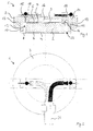
- Reference number 1 designates the ultrasonic transducer in its entirety.
- the ultrasonic transducer 1 is particularly suitable for use in a flow meter for liquid or designed gaseous medium. It has a piezoelectric disk 2, which in one Pot-shaped converter housing 3 is arranged with an open side 22 and at the medium facing front 4 a first electrode 6 and on the back 5 a second electrode 7 is arranged. Furthermore, the first electrode 6 has a first connection electrode and the second electrode 7 with a second connection electrode 9 for Power supply contacted.
- the power cable for the power supply is with reference number 21 provided.
- the first connection electrode is designed as a membrane 8 and additionally provided for converter housing 3. The membrane 8 closes the open side 22 of the pot-shaped transducer housing 3.
- the piezoelectric Disc 2 held securely and stably in the receptacle 10.
- the piezoelectric disc 2 is a thickness resonance transducer.
- unwanted or parasitic waveforms such as radial or diagonal vibrations
- Precautions are to be taken at the same time as the construction hit that suppress these forms of vibration.
- the membrane 8 is in direct contact with the medium to be measured, such as. B. from Fig. 9 emerges.
- the membrane 8 is also cup-shaped and with the converter housing 3 assembled so that the receptacle 10 is formed.
- This Design of the ultrasonic transducer allows a high degree of automation in its Production.
- the piezoelectric disk 2 lies on a protruding support 16 of the converter housing 3 on.
- the support 16 is annular in Fig. 1. In the other figures the support 16 is flat.
- the piezoelectric disc 2 is therefore in one axial direction stable and can move freely towards the diaphragm as well as radially swing.
- the piezoelectric disk 2 is also fixed by the membrane 8 edition of 16.
- the pad 16 is an integral part of the converter housing 3.
- the membrane 8 has a circumferential edge 12 which is connected to a circumferential web 11 of the converter housing 3 rests on the outside.
- the peripheral edge 12 of the membrane 8 can enclose circumferential web 11 in a form-fitting manner. This connection can also be done using an adhesive layer between edge 12 and web 11 can be secured or sealed.
- the diameter of the pad 16 is at least as large as the diameter of the piezoelectric Disc 2, to ensure a stable support of disc 2.
- the second connection electrode 9 is with the piezoelectric disc 2 and the second Glued electrode 7. On the other hand, the second connection electrode 9 is also supported 16 glued, which is used a double-sided tape to ensure a constant Gap and thus ensure optimal measurement behavior.
- the membrane 8 with the piezoelectric disk 2 or the first electrode 6 glued is glued.
- the first and second connection electrodes 8, 9 each point upwards of an electrical connection projecting flag 14, 15. These flags 14, 15 serve at the same time - at least in the membrane 8 - as an extension of the cup-shaped edge 12 and form contact tongues for connection (e.g. plug connection) to the power cable 21st
- the flags 14, 15 of the first and second connection electrodes 8, 9 pass through openings 18 of the converter housing 3 to the outside and are in the openings 18 by means of a suitable adhesive sealed and thus relieved of strain at the same time.
- the flag 15 of the second connection electrode 9 or a projection 26 of the flag 15 is supported against a level 23 of the converter housing 3.
- the stage 23 is on a column 25 of the converter housing 3 provided. This support provides strain relief for the flag 15 reached (see. Supporting the flag 15 Fig. 5 and 6).
- a brim 27 is provided on the membrane 8, which in the groove 24 lies.
- the piezoelectric disk 2 is fixed in position by the membrane 8 and lies nevertheless without preload on the pad 16, so that they have an optimal vibration behavior can train.
- the space 17 formed by the above support 16 and the membrane 8 is shown in FIG. 1 filled with air and thus almost ultrasonically insulating.
- the piezoelectric disc 2 is spaced from the web 11 of the converter housing 3 or the edge 12 of the membrane 8, so that the piezoelectric disc can vibrate radially freely. In addition, through this Distance a receiving reservoir for excess adhesive or adhesive burrs is formed, which therefore do not affect the swinging of the disc.
- the glue is attached to the attachment of the piezoelectric disc 2 with the pad 16 or also provided on other connections of the components.
- the support 16 and the converter housing 3 also exist with the full-surface support 16 made of PVDF, which has the advantage that it can be used for many parameters, especially for Impedance of the water is adapted. Of course, this is only an advantage if it is the medium to be measured is also water.
- the second connection electrode 9 can also be formed by a metallic coating.
- the diameter of the piezoelectric disc 2 is at most 7.5 mm.
- the diameter the piezoelectric disk 2 is 3.3 to 3.8 times larger than the one designed for 1 MHz Thickness.
- the membrane 8 brings about a long-term and temperature-stable fixation of the piezoelectric Disc 2 and thus ensures constant measurements over a long time very small offset.
- the converter housing 1 or the web 11 or the Surface 13 have a groove in which the membrane 8 is immersed. This groove can go through Melt a peripheral nose of the converter housing 3 additionally filled with adhesive be so that the ultrasonic transducer 1 is waterproof.
- Transducer housing 3 and membrane 8 can have corresponding bevels, so the parts can easily collapse during assembly.
- the ultrasonic transducer shown in FIG. 7 has a transducer housing 3 with a support 16, which is formed over the entire area essentially over the entire surface of the rear side 5 of the piezoelectric disk 2.
- the second connection electrode 9 is glued to the support 16, which improves the quality, the vibrating structure remains stable and unevenness is compensated for.
- the full-surface design of the support 16 means that the piezoelectric disc 2 always lies flat and the measurement quality of the transducer remains constant.
- the thickness of the pad 16 (so-called absorber height) is 3.55 mm. 8 shows a possible arrangement of the two ultrasonic transducers 1, the direction of flow of the medium being indicated by the arrows.
- each ultrasonic transducer 1 has one separate converter housing 3 and a membrane 8 each.
- the membrane 8 fixed one piezoelectric disk 2 each.
- the sound path runs across the water path. In order for the entrainment effect to occur, the sound must be deflected by means of a mirror. The However, mirrors for sound deflection were not shown.
- an ultrasonic transducer 1 in which two piezoelectric Disks 2 are arranged in a common converter housing 3.
- the two piezoelectric Disks 2 are also contacted by a common membrane 8.
- the technical advantages with this arrangement are that fewer parts are required be, a simpler connection is made possible and a smaller construction as a result the shorter distance between the two piezoelectric disks 2 to each other becomes.
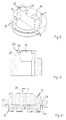
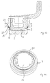
- the ultrasound transducer 1 shown in FIGS. 11, 12 and 13 points in contrast to the previous ultrasonic transducers no pot-shaped transducer housing in the sense of the figures 1 to 10.
- the ultrasonic transducer according to FIGS. 11, 12 and 13 is the first Connection electrode also formed as a membrane 8 and in addition to the converter housing 3 provided, the membrane 8 closes the converter housing 3.
- the piezoelectric disk 2 is safe due to the cup-shaped Membrane 8 held on the converter housing 3.
- the membrane 8 is also directly with in contact with the medium to be measured.
- the membrane 8 also has a brim 27 on, which lies in Figures 11 and 13 in a groove 24 of the converter housing 3. In Figure 12, however, is the upper part of the edge 12 of the membrane 8 and the circumferential Brim 27 by means of a casting compound 29 in a circumferential recess of the converter housing 3 poured.
- the circumferential edge 12 of the membrane 8 extends to a circumferential web 11 of the converter housing 3 to form a gap 28.
- the gap 28 ensures decoupling of membrane 8 and converter housing 3, so that these elements change with temperature fluctuations expand or contract as freely as possible.
- the converter housing 3 shown in FIG. 14 shows a full-surface support 16 for the piezoelectric disc. Centering pins 30 are arranged on the support 16, on which the second connection electrode 9 is adjacent and thus fixed in its position becomes. However, the second connection electrode 9 is not shown in FIG. 14.
Landscapes
- Physics & Mathematics (AREA)
- Electromagnetism (AREA)
- Fluid Mechanics (AREA)
- General Physics & Mathematics (AREA)
- Engineering & Computer Science (AREA)
- Acoustics & Sound (AREA)
- Multimedia (AREA)
- Measuring Volume Flow (AREA)
- Transducers For Ultrasonic Waves (AREA)
- Measurement Of Velocity Or Position Using Acoustic Or Ultrasonic Waves (AREA)
Applications Claiming Priority (2)
| Application Number | Priority Date | Filing Date | Title |
|---|---|---|---|
| DE10158015 | 2001-11-27 | ||
| DE10158015A DE10158015B4 (de) | 2001-11-27 | 2001-11-27 | Ultraschallwandler und Durchflussmesser |
Publications (3)
| Publication Number | Publication Date |
|---|---|
| EP1315144A2 true EP1315144A2 (fr) | 2003-05-28 |
| EP1315144A3 EP1315144A3 (fr) | 2010-03-17 |
| EP1315144B1 EP1315144B1 (fr) | 2011-07-06 |
Family
ID=7707040
Family Applications (1)
| Application Number | Title | Priority Date | Filing Date |
|---|---|---|---|
| EP02026525A Expired - Lifetime EP1315144B1 (fr) | 2001-11-27 | 2002-11-27 | Transducteur à ultrasons et débitmètre |
Country Status (4)
| Country | Link |
|---|---|
| EP (1) | EP1315144B1 (fr) |
| AT (1) | ATE515765T1 (fr) |
| DE (1) | DE10158015B4 (fr) |
| DK (1) | DK1315144T3 (fr) |
Cited By (5)
| Publication number | Priority date | Publication date | Assignee | Title |
|---|---|---|---|---|
| WO2005052519A3 (fr) * | 2003-11-27 | 2005-11-10 | Flowtec Ag | Dispositif pour la determination et/ou la surveillance du debit volumique et/ou massique d'un fluide |
| WO2011051041A1 (fr) * | 2009-10-29 | 2011-05-05 | Robert Bosch Gmbh | Transducteur ultrasonore destiné à être utilisé dans un milieu fluide |
| CN102333271A (zh) * | 2010-06-16 | 2012-01-25 | 罗伯特·博世有限公司 | 用于制造用于在流体介质中使用的超声波换能器的方法 |
| EP3444573A1 (fr) * | 2017-08-17 | 2019-02-20 | Landis+Gyr GmbH | Tête à ultrasons pour un débitmètre doté des moyens d'extraction |
| KR20230021127A (ko) * | 2020-07-03 | 2023-02-13 | 후바 콘트롤 아게 | 센서 어셈블리 |
Families Citing this family (7)
| Publication number | Priority date | Publication date | Assignee | Title |
|---|---|---|---|---|
| DE102006008718B4 (de) * | 2006-02-24 | 2017-05-18 | Volkswagen Ag | Ultraschallsensormodul |
| DE102008027687A1 (de) * | 2008-06-11 | 2009-12-17 | Valeo Schalter Und Sensoren Gmbh | Ultraschallwandler |
| DE102009052814B3 (de) * | 2009-11-13 | 2011-05-19 | Hydrometer Gmbh | Ultraschallwandler-Anordnung und Durchflussmesser |
| DE102010000967A1 (de) | 2010-01-18 | 2011-07-21 | Robert Bosch GmbH, 70469 | Ultraschallwandler zum Einsatz in einem fluiden Medium |
| DE102011016963A1 (de) * | 2011-04-13 | 2012-10-18 | Hydrometer Gmbh | Verfahren zur Messung von Durchflussmengen nach dem Prinzip der Ultraschalllaufzeitdifferenz |
| EP2602596A1 (fr) | 2011-12-09 | 2013-06-12 | Kamstrup A/S | Débitmètre à ultrasons sur un PCB |
| DE102018201404B3 (de) | 2018-01-30 | 2019-04-11 | Pi Ceramic Gmbh | Ultraschallwandler mit einer Piezokeramik und Verfahren zur Herstellung eines solchen Ultraschallwandlers |
Citations (3)
| Publication number | Priority date | Publication date | Assignee | Title |
|---|---|---|---|---|
| DE2934031B1 (de) | 1979-08-02 | 1980-10-09 | Landis & Gyr Ag | Ultraschallwandler |
| EP0679874A2 (fr) | 1994-04-25 | 1995-11-02 | Siemens Aktiengesellschaft | Capteur du son |
| EP0897101A1 (fr) | 1997-08-14 | 1999-02-17 | Electrowatt Technology Innovation AG | Débitmètre à ultrason |
Family Cites Families (11)
| Publication number | Priority date | Publication date | Assignee | Title |
|---|---|---|---|---|
| US4228379A (en) * | 1978-08-28 | 1980-10-14 | American District Telegraph Company | Diaphragm type piezoelectric electroacoustic transducer |
| DE3347442A1 (de) * | 1983-12-29 | 1985-07-11 | Bayerische Motoren Werke Ag | Einrichtung zur abstandsmessung, insbesondere fuer kraftfahrzeuge |
| JPS60216698A (ja) * | 1984-04-12 | 1985-10-30 | Matsushita Electric Ind Co Ltd | 超音波セラミツクマイクロホン |
| DE3441684A1 (de) * | 1984-11-15 | 1986-05-15 | SWF Auto-Electric GmbH, 7120 Bietigheim-Bissingen | Elektroakustischer wandler |
| US4754440A (en) * | 1985-12-27 | 1988-06-28 | Aisin Seiki Kabushikikaisha | Ultrasonic transducer |
| JPH0749914Y2 (ja) * | 1986-01-29 | 1995-11-13 | 株式会社村田製作所 | 超音波トランスデユ−サ |
| DE4215271A1 (de) * | 1992-05-09 | 1993-11-11 | Tridelta Ag | Ultraschallwandler |
| JP3721798B2 (ja) * | 1998-01-13 | 2005-11-30 | 株式会社村田製作所 | 超音波センサ |
| JP3796969B2 (ja) * | 1998-07-01 | 2006-07-12 | 株式会社村田製作所 | 超音波センサ |
| DE10009129A1 (de) * | 2000-02-26 | 2001-08-30 | Volkswagen Ag | Ultraschallsensor |
| DE10055893C5 (de) * | 2000-11-10 | 2010-04-01 | Hydrometer Gmbh | Ultraschallwandler-Anordnung für den Einsatz in einem Durchflußmesser für ein gasförmiges oder flüssiges Medium |
-
2001
- 2001-11-27 DE DE10158015A patent/DE10158015B4/de not_active Expired - Fee Related
-
2002
- 2002-11-27 AT AT02026525T patent/ATE515765T1/de active
- 2002-11-27 DK DK02026525.2T patent/DK1315144T3/da active
- 2002-11-27 EP EP02026525A patent/EP1315144B1/fr not_active Expired - Lifetime
Patent Citations (3)
| Publication number | Priority date | Publication date | Assignee | Title |
|---|---|---|---|---|
| DE2934031B1 (de) | 1979-08-02 | 1980-10-09 | Landis & Gyr Ag | Ultraschallwandler |
| EP0679874A2 (fr) | 1994-04-25 | 1995-11-02 | Siemens Aktiengesellschaft | Capteur du son |
| EP0897101A1 (fr) | 1997-08-14 | 1999-02-17 | Electrowatt Technology Innovation AG | Débitmètre à ultrason |
Cited By (15)
| Publication number | Priority date | Publication date | Assignee | Title |
|---|---|---|---|---|
| US7614309B2 (en) | 2003-11-27 | 2009-11-10 | Endress & Hauser Flowtec Ag | Cup-shaped ultrasonic transducer for a flowmeter |
| WO2005052519A3 (fr) * | 2003-11-27 | 2005-11-10 | Flowtec Ag | Dispositif pour la determination et/ou la surveillance du debit volumique et/ou massique d'un fluide |
| CN102667417B (zh) * | 2009-10-29 | 2016-01-20 | 罗伯特·博世有限公司 | 用于在流体介质中使用的超声波换能器 |
| WO2011051041A1 (fr) * | 2009-10-29 | 2011-05-05 | Robert Bosch Gmbh | Transducteur ultrasonore destiné à être utilisé dans un milieu fluide |
| CN102667417A (zh) * | 2009-10-29 | 2012-09-12 | 罗伯特·博世有限公司 | 用于在流体介质中使用的超声波换能器 |
| US8988971B2 (en) | 2009-10-29 | 2015-03-24 | Robert Bosch Gmbh | Ultrasonic transducer for use in a fluid medium |
| RU2551550C2 (ru) * | 2009-10-29 | 2015-05-27 | Роберт Бош Гмбх | Ультразвуковой преобразователь для применения в текучей среде |
| CN102333271A (zh) * | 2010-06-16 | 2012-01-25 | 罗伯特·博世有限公司 | 用于制造用于在流体介质中使用的超声波换能器的方法 |
| CN102333271B (zh) * | 2010-06-16 | 2016-04-27 | 罗伯特·博世有限公司 | 在流体介质中使用的超声波换能器及其制造方法 |
| EP3444573A1 (fr) * | 2017-08-17 | 2019-02-20 | Landis+Gyr GmbH | Tête à ultrasons pour un débitmètre doté des moyens d'extraction |
| CN109405903A (zh) * | 2017-08-17 | 2019-03-01 | 兰吉尔有限公司 | 用于流量计的具有拉出装置的声探头 |
| KR20230021127A (ko) * | 2020-07-03 | 2023-02-13 | 후바 콘트롤 아게 | 센서 어셈블리 |
| CN115769052A (zh) * | 2020-07-03 | 2023-03-07 | 瑞士富巴自动化控制股份有限公司 | 传感器组件 |
| US20230288237A1 (en) * | 2020-07-03 | 2023-09-14 | Huba Control Ag | Sensor Assembly |
| US12442673B2 (en) * | 2020-07-03 | 2025-10-14 | Huba Control Ag | Sensor assembly |
Also Published As
| Publication number | Publication date |
|---|---|
| ATE515765T1 (de) | 2011-07-15 |
| DE10158015B4 (de) | 2010-10-14 |
| DE10158015A1 (de) | 2003-06-05 |
| EP1315144B1 (fr) | 2011-07-06 |
| DK1315144T3 (da) | 2011-10-03 |
| EP1315144A3 (fr) | 2010-03-17 |
Similar Documents
| Publication | Publication Date | Title |
|---|---|---|
| DE2828148C2 (de) | Biegeanordnung | |
| EP0769684B1 (fr) | Système de surveillance d'un niveau prédéterminé d'un fluide dans un récipient | |
| DE10158015B4 (de) | Ultraschallwandler und Durchflussmesser | |
| DE3525724C2 (fr) | ||
| EP0447516B1 (fr) | Indicateur de niveau forme de composants assemblables | |
| DE2934031C2 (de) | Ultraschallwandler | |
| EP1997100B1 (fr) | Capteur à ultrasons | |
| DE102004018301B4 (de) | Piezoelektrischer elektroakustischer Wandler | |
| EP0507892B1 (fr) | Transducteur ultrasonore | |
| DE10226384A1 (de) | Piezoelektrischer elekroakustischer Wandler und Herstellverfahren hierfür | |
| DE102008016558A1 (de) | Baugruppe mit einem Stoßfänger und einem Ultraschallsensor | |
| DE2749987A1 (de) | Ultraschall-wandler | |
| DE10354026B4 (de) | Piezoelektrische Membran und deren Verwendung in einem elektroakustischen Wandler | |
| DE102015004049B4 (de) | Ultraschallzähler | |
| DE3032221A1 (de) | Schallwandler | |
| DE102004031310B4 (de) | Membrantopf für einen Ultraschallwandler | |
| DE2126556A1 (de) | Mikrophonkapsel mit Verstärker | |
| DE69911861T2 (de) | Elektroakustischer wandler und membran für elektroakustischen wandler | |
| DE102011079646A1 (de) | Ultraschallsensorvorrichtung zum Erfassen und/oder Senden von Ultraschall | |
| DE10229845A1 (de) | Piezoelektrischer Elektroakustischer Transducer | |
| DE102004011751A1 (de) | Piezoelektrischer elektroakustischer Wandler und sein Herstellungsverfahren | |
| DE3808019A1 (de) | Ultraschall-sensor | |
| DE202007007135U1 (de) | Piezoelektrischer Ultraschallwandler | |
| DE3234060C2 (de) | Elektrostatischer Wandler | |
| EP0790490B1 (fr) | Capteur à ultrasons pour la détermination du débit d'un liquide en écoulement |
Legal Events
| Date | Code | Title | Description |
|---|---|---|---|
| PUAI | Public reference made under article 153(3) epc to a published international application that has entered the european phase |
Free format text: ORIGINAL CODE: 0009012 |
|
| AK | Designated contracting states |
Designated state(s): AT BE BG CH CY CZ DE DK EE ES FI FR GB GR IE IT LI LU MC NL PT SE SK TR |
|
| AX | Request for extension of the european patent |
Extension state: AL LT LV MK RO SI |
|
| PUAL | Search report despatched |
Free format text: ORIGINAL CODE: 0009013 |
|
| AK | Designated contracting states |
Kind code of ref document: A3 Designated state(s): AT BE BG CH CY CZ DE DK EE ES FI FR GB GR IE IT LI LU MC NL PT SE SK TR |
|
| AX | Request for extension of the european patent |
Extension state: AL LT LV MK RO SI |
|
| 17P | Request for examination filed |
Effective date: 20100811 |
|
| 17Q | First examination report despatched |
Effective date: 20101026 |
|
| AKX | Designation fees paid |
Designated state(s): AT BE BG CH CY CZ DE DK EE ES FI FR GB GR IE IT LI LU MC NL PT SE SK TR |
|
| GRAP | Despatch of communication of intention to grant a patent |
Free format text: ORIGINAL CODE: EPIDOSNIGR1 |
|
| GRAS | Grant fee paid |
Free format text: ORIGINAL CODE: EPIDOSNIGR3 |
|
| GRAA | (expected) grant |
Free format text: ORIGINAL CODE: 0009210 |
|
| REG | Reference to a national code |
Ref country code: DE Ref legal event code: R081 Ref document number: 50215114 Country of ref document: DE Owner name: DIEHL METERING GMBH, DE Free format text: FORMER OWNER: HYDROMETER GMBH, 91522 ANSBACH, DE |
|
| AK | Designated contracting states |
Kind code of ref document: B1 Designated state(s): AT BE BG CH CY CZ DE DK EE ES FI FR GB GR IE IT LI LU MC NL PT SE SK TR |
|
| REG | Reference to a national code |
Ref country code: GB Ref legal event code: FG4D Free format text: NOT ENGLISH |
|
| REG | Reference to a national code |
Ref country code: CH Ref legal event code: EP |
|
| REG | Reference to a national code |
Ref country code: IE Ref legal event code: FG4D Free format text: LANGUAGE OF EP DOCUMENT: GERMAN |
|
| REG | Reference to a national code |
Ref country code: DE Ref legal event code: R096 Ref document number: 50215114 Country of ref document: DE Effective date: 20110825 |
|
| REG | Reference to a national code |
Ref country code: DK Ref legal event code: T3 |
|
| REG | Reference to a national code |
Ref country code: NL Ref legal event code: VDEP Effective date: 20110706 |
|
| PG25 | Lapsed in a contracting state [announced via postgrant information from national office to epo] |
Ref country code: PT Free format text: LAPSE BECAUSE OF FAILURE TO SUBMIT A TRANSLATION OF THE DESCRIPTION OR TO PAY THE FEE WITHIN THE PRESCRIBED TIME-LIMIT Effective date: 20111107 Ref country code: SE Free format text: LAPSE BECAUSE OF FAILURE TO SUBMIT A TRANSLATION OF THE DESCRIPTION OR TO PAY THE FEE WITHIN THE PRESCRIBED TIME-LIMIT Effective date: 20110706 Ref country code: FI Free format text: LAPSE BECAUSE OF FAILURE TO SUBMIT A TRANSLATION OF THE DESCRIPTION OR TO PAY THE FEE WITHIN THE PRESCRIBED TIME-LIMIT Effective date: 20110706 Ref country code: NL Free format text: LAPSE BECAUSE OF FAILURE TO SUBMIT A TRANSLATION OF THE DESCRIPTION OR TO PAY THE FEE WITHIN THE PRESCRIBED TIME-LIMIT Effective date: 20110706 |
|
| REG | Reference to a national code |
Ref country code: IE Ref legal event code: FD4D |
|
| PG25 | Lapsed in a contracting state [announced via postgrant information from national office to epo] |
Ref country code: GR Free format text: LAPSE BECAUSE OF FAILURE TO SUBMIT A TRANSLATION OF THE DESCRIPTION OR TO PAY THE FEE WITHIN THE PRESCRIBED TIME-LIMIT Effective date: 20111007 Ref country code: CY Free format text: LAPSE BECAUSE OF FAILURE TO SUBMIT A TRANSLATION OF THE DESCRIPTION OR TO PAY THE FEE WITHIN THE PRESCRIBED TIME-LIMIT Effective date: 20110706 |
|
| PG25 | Lapsed in a contracting state [announced via postgrant information from national office to epo] |
Ref country code: SK Free format text: LAPSE BECAUSE OF FAILURE TO SUBMIT A TRANSLATION OF THE DESCRIPTION OR TO PAY THE FEE WITHIN THE PRESCRIBED TIME-LIMIT Effective date: 20110706 Ref country code: CZ Free format text: LAPSE BECAUSE OF FAILURE TO SUBMIT A TRANSLATION OF THE DESCRIPTION OR TO PAY THE FEE WITHIN THE PRESCRIBED TIME-LIMIT Effective date: 20110706 Ref country code: IE Free format text: LAPSE BECAUSE OF FAILURE TO SUBMIT A TRANSLATION OF THE DESCRIPTION OR TO PAY THE FEE WITHIN THE PRESCRIBED TIME-LIMIT Effective date: 20110706 |
|
| PLBE | No opposition filed within time limit |
Free format text: ORIGINAL CODE: 0009261 |
|
| STAA | Information on the status of an ep patent application or granted ep patent |
Free format text: STATUS: NO OPPOSITION FILED WITHIN TIME LIMIT |
|
| BERE | Be: lapsed |
Owner name: HYDROMETER G.M.B.H. Effective date: 20111130 |
|
| PG25 | Lapsed in a contracting state [announced via postgrant information from national office to epo] |
Ref country code: EE Free format text: LAPSE BECAUSE OF FAILURE TO SUBMIT A TRANSLATION OF THE DESCRIPTION OR TO PAY THE FEE WITHIN THE PRESCRIBED TIME-LIMIT Effective date: 20110706 Ref country code: IT Free format text: LAPSE BECAUSE OF FAILURE TO SUBMIT A TRANSLATION OF THE DESCRIPTION OR TO PAY THE FEE WITHIN THE PRESCRIBED TIME-LIMIT Effective date: 20110706 |
|
| 26N | No opposition filed |
Effective date: 20120411 |
|
| PG25 | Lapsed in a contracting state [announced via postgrant information from national office to epo] |
Ref country code: MC Free format text: LAPSE BECAUSE OF NON-PAYMENT OF DUE FEES Effective date: 20111130 |
|
| REG | Reference to a national code |
Ref country code: CH Ref legal event code: PL |
|
| PG25 | Lapsed in a contracting state [announced via postgrant information from national office to epo] |
Ref country code: CH Free format text: LAPSE BECAUSE OF NON-PAYMENT OF DUE FEES Effective date: 20111130 Ref country code: LI Free format text: LAPSE BECAUSE OF NON-PAYMENT OF DUE FEES Effective date: 20111130 |
|
| REG | Reference to a national code |
Ref country code: DE Ref legal event code: R097 Ref document number: 50215114 Country of ref document: DE Effective date: 20120411 |
|
| REG | Reference to a national code |
Ref country code: FR Ref legal event code: ST Effective date: 20120731 |
|
| PG25 | Lapsed in a contracting state [announced via postgrant information from national office to epo] |
Ref country code: BE Free format text: LAPSE BECAUSE OF NON-PAYMENT OF DUE FEES Effective date: 20111130 |
|
| PG25 | Lapsed in a contracting state [announced via postgrant information from national office to epo] |
Ref country code: FR Free format text: LAPSE BECAUSE OF NON-PAYMENT OF DUE FEES Effective date: 20111130 |
|
| REG | Reference to a national code |
Ref country code: AT Ref legal event code: MM01 Ref document number: 515765 Country of ref document: AT Kind code of ref document: T Effective date: 20111127 |
|
| PG25 | Lapsed in a contracting state [announced via postgrant information from national office to epo] |
Ref country code: AT Free format text: LAPSE BECAUSE OF NON-PAYMENT OF DUE FEES Effective date: 20111127 |
|
| PG25 | Lapsed in a contracting state [announced via postgrant information from national office to epo] |
Ref country code: ES Free format text: LAPSE BECAUSE OF FAILURE TO SUBMIT A TRANSLATION OF THE DESCRIPTION OR TO PAY THE FEE WITHIN THE PRESCRIBED TIME-LIMIT Effective date: 20111017 |
|
| PG25 | Lapsed in a contracting state [announced via postgrant information from national office to epo] |
Ref country code: LU Free format text: LAPSE BECAUSE OF NON-PAYMENT OF DUE FEES Effective date: 20111127 |
|
| PG25 | Lapsed in a contracting state [announced via postgrant information from national office to epo] |
Ref country code: BG Free format text: LAPSE BECAUSE OF FAILURE TO SUBMIT A TRANSLATION OF THE DESCRIPTION OR TO PAY THE FEE WITHIN THE PRESCRIBED TIME-LIMIT Effective date: 20111006 |
|
| REG | Reference to a national code |
Ref country code: DE Ref legal event code: R081 Ref document number: 50215114 Country of ref document: DE Owner name: DIEHL METERING GMBH, DE Free format text: FORMER OWNER: HYDROMETER GMBH, 91522 ANSBACH, DE |
|
| PGFP | Annual fee paid to national office [announced via postgrant information from national office to epo] |
Ref country code: DK Payment date: 20191122 Year of fee payment: 18 |
|
| PGFP | Annual fee paid to national office [announced via postgrant information from national office to epo] |
Ref country code: TR Payment date: 20191121 Year of fee payment: 18 |
|
| PGFP | Annual fee paid to national office [announced via postgrant information from national office to epo] |
Ref country code: GB Payment date: 20191120 Year of fee payment: 18 Ref country code: DE Payment date: 20200122 Year of fee payment: 18 |
|
| REG | Reference to a national code |
Ref country code: DE Ref legal event code: R119 Ref document number: 50215114 Country of ref document: DE |
|
| REG | Reference to a national code |
Ref country code: DK Ref legal event code: EBP Effective date: 20201130 |
|
| GBPC | Gb: european patent ceased through non-payment of renewal fee |
Effective date: 20201127 |
|
| PG25 | Lapsed in a contracting state [announced via postgrant information from national office to epo] |
Ref country code: DE Free format text: LAPSE BECAUSE OF NON-PAYMENT OF DUE FEES Effective date: 20210601 Ref country code: GB Free format text: LAPSE BECAUSE OF NON-PAYMENT OF DUE FEES Effective date: 20201127 Ref country code: DK Free format text: LAPSE BECAUSE OF NON-PAYMENT OF DUE FEES Effective date: 20201130 |
|
| PG25 | Lapsed in a contracting state [announced via postgrant information from national office to epo] |
Ref country code: TR Free format text: LAPSE BECAUSE OF NON-PAYMENT OF DUE FEES Effective date: 20201127 |