EP1315149A2 - Verfahren und Vorrichtung zur Beseitigung von Diskontinuitäten eines adaptiv gefilterten Signals - Google Patents
Verfahren und Vorrichtung zur Beseitigung von Diskontinuitäten eines adaptiv gefilterten Signals Download PDFInfo
- Publication number
- EP1315149A2 EP1315149A2 EP02256894A EP02256894A EP1315149A2 EP 1315149 A2 EP1315149 A2 EP 1315149A2 EP 02256894 A EP02256894 A EP 02256894A EP 02256894 A EP02256894 A EP 02256894A EP 1315149 A2 EP1315149 A2 EP 1315149A2
- Authority
- EP
- European Patent Office
- Prior art keywords
- filtered
- signal
- filter
- frame
- term
- Prior art date
- Legal status (The legal status is an assumption and is not a legal conclusion. Google has not performed a legal analysis and makes no representation as to the accuracy of the status listed.)
- Granted
Links
Images


Classifications
-
- G—PHYSICS
- G10—MUSICAL INSTRUMENTS; ACOUSTICS
- G10L—SPEECH ANALYSIS TECHNIQUES OR SPEECH SYNTHESIS; SPEECH RECOGNITION; SPEECH OR VOICE PROCESSING TECHNIQUES; SPEECH OR AUDIO CODING OR DECODING
- G10L19/00—Speech or audio signals analysis-synthesis techniques for redundancy reduction, e.g. in vocoders; Coding or decoding of speech or audio signals, using source filter models or psychoacoustic analysis
- G10L19/04—Speech or audio signals analysis-synthesis techniques for redundancy reduction, e.g. in vocoders; Coding or decoding of speech or audio signals, using source filter models or psychoacoustic analysis using predictive techniques
- G10L19/26—Pre-filtering or post-filtering
Definitions
- the present invention relates generally to techniques for filtering signals, and more particularly, to techniques to eliminate discontinuities in adaptively filtered signals.
- a properly designed adaptive filter applied at the output of the speech decoder is capable of reducing the perceived coding noise, thus improving the quality of the decoded speech.
- Such an adaptive filter is often called an adaptive postfilter, and the adaptive postfilter is said to perform adaptive postfiltering.
- Adaptive postfiltering can be performed using frequency-domain approaches, that is, using a frequency-domain postfilter.
- Conventional frequency-domain approaches disadvantageously require relatively high computational complexity, and introduce undesirable buffering delay for overlap-add operations used to avoid waveform discontinuities at block boundaries. Therefore, there is a need for an adaptive postfilter that can improve the quality of decoded speech, while reducing computational complexity and buffering delay relative to conventional frequency-domain postfilters.
- Adaptive postfiltering can also be performed using time-domain approaches, that is, using a time-domain adaptive postfilter.
- a known time-domain adaptive postfilter includes a long-term postfilter and a short-term postfilter.
- the long-term postfilter is used when the speech spectrum has a harmonic structure, for example, during voiced speech when the speech waveform is almost periodic.
- the long-term postfilter is typically used to perform long-term filtering to attenuate spectral valleys between harmonics in the speech spectrum.
- the short-term postfilter performs short-term filtering to attenuate the valleys in the spectral envelope, i.e., the valleys between formant peaks.
- a disadvantage of some of the older time-domain adaptive postfilters is that they tend to make the postfiltered speech sound muffled, because they tend to have a lowpass spectral tilt during voiced speech. More recently proposed conventional time-domain postfilters greatly reduce such spectral tilt, but at the expense of using much more complicated filter structures to achieve this goal. Therefore, there is a need for an adaptive postfilter that reduces such spectral tilt with a simple filter structure.
- an adaptive postfilter include adaptive gain control (AGC).
- AGC adaptive gain control
- AGC can disadvantageously increase the computational complexity of the adaptive postfilter. Therefore, there is a need for an adaptive postfilter including AGC, where the computational complexity associated with the AGC is minimized.
- Embodiments of the present invention use a time-domain adaptive postfiltering approach. That is, the embodiments use a time-domain adaptive postfilter for improving decoded speech quality, while reducing computational complexity and buffering delay relative to conventional frequency-domain postfiltering approaches. When compared with conventional time-domain adaptive postfilters, the embodiments use a simpler filter structure.
- the time-domain adaptive postfilter of the embodiments includes a short-term filter and a long-term filter.
- the short-term filter is an all-pole filter.
- the all-pole short-term filter has minimal spectral tilt, and thus, reduces muffling in the decoded speech.
- the simple all-pole short-term filter of the embodiments achieves a lower degree of spectral tilt than other known short-term postfilters that use more complicated filter structures.
- the postfilter of the embodiments does not require the use of individual scaling factors for the long-term postfilter and the short-term postfilter.
- the embodiments only needs to apply a single AGC scaling factor at the end of the filtering operations, without adversely affecting decoded speech quality.
- the AGC scaling factor is calculated only once a sub-frame, thereby reducing computational complexity in the embodiments.
- the embodiments do not require a sample-by-sample lowpass smoothing of the AGC scaling factor, further reducing computational complexity.
- the postfilter advantageously avoids waveform discontinuity at sub-frame boundaries, because it employs a novel overlap-add operation that smoothes, and thus, substantially eliminates, possible waveform discontinuity.
- This novel overlap-add operation does not increase the buffering delay of the filter in the embodiments.
- An embodiment of the present invention is a method of smoothing an adaptively filtered signal.
- the signal includes successive signal frames of signal samples.
- the signal can be any signal, such as a speech and/or audio related signal.
- the method comprises: (a) filtering a beginning portion of a current signal frame using a past set of filter coefficients, thereby producing a first filtered frame portion; (b) filtering the beginning portion of the current signal frame using a current set of filter coefficients, thereby producing a second filtered frame portion; and (c) modifying the second filtered frame portion with the first filtered frame portion so as to smooth, and thus, substantially eliminate, a possible filtered signal discontinuity between the second filtered frame portion and a past filtered frame produced using the past filter coefficients.
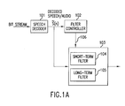
- FIG. 1A is block diagram of an example postfilter system for processing speech and/or audio related signals, according to an embodiment of the present invention.
- FIG. 1B is block diagram of a Prior Art adaptive postfilter in the ITU-T Recommendation G.729 speech coding standard.
- FIGs. 2A is a block diagram of an example filter controller of FIG. 1A for deriving short-term filter coefficients.
- FIGs. 2B is a block diagram of another example filter controller of FIG. 1A for deriving short-term filter coefficients.
- FIGs. 2C, 2D and 2E each include illustrations of a decoded speech spectrum and filter responses related to the filter controller of FIG. 1A.
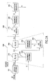
- FIG. 3 is a block diagram of an example adaptive postfilter of the postfilter system of FIG. 1A.
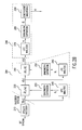
- FIG. 4 is a block diagram of an alternative adaptive postfilter of the postfilter system of FIG. 1A.
- FIG. 5 is a flow chart of an example method of adaptively filtering a decoded speech signal to smooth signal discontinuities that may arise from a filter update at a speech frame boundary.
- FIG. 6 is a high-level block diagram of an example adaptive filter.
- FIG. 7 is a timing diagram for example portions of various signals discussed in connection with the filter of FIG. 7.
- FIG. 8 is a flow chart of an example generalized method of adaptively filtering a generalized signal to smooth filtered signal discontinuities that may arise from a filter update.
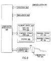
- FIG. 9 is a block diagram of a computer system on which the present invention may operate.
- the speech signal is typically encoded and decoded frame by frame, where each frame has a fixed length somewhere between 5 ms to 40 ms.
- each frame is often further divided into equal-length sub-frames, with each sub-frame typically lasting somewhere between 1 and 10 ms.
- Most adaptive postfilters are adapted sub-frame by sub-frame. That is, the coefficients and parameters of the postfilter are updated only once a sub-frame, and are held constant within each sub-frame. This is true for the conventional adaptive postfilter and the embodiments described below.
- FIG. 1A is block diagram of an example postfilter system for processing speech and/or audio related signals, according to an embodiment of the present invention.
- the system includes a speech decoder 101 (which forms no part of the present invention), a filter controller 102, and an adaptive postfilter 103 (also referred to as a filter 103) controlled by controller 102.
- Filter 103 includes a short-term postfilter 104 and a long-term postfilter 105 (also referred to as filters 104 and 105, respectively).
- Speech decoder 101 receives a bit stream representative of an encoded speech and/or audio signal. Decoder 101 decodes the bit stream to produce a decoded speech (DS) signal ( n ).
- Filter controller 102 processes DS signal ( n ) to derive/produce filter control signals 106 for controlling filter 103, and provides the control signals to the filter.
- Filter control signals 106 control the properties of filter 103, and include, for example, short-term filter coefficients d i for short-term filter 104, long-term filter coefficients for long-term filter 105, AGC gains, and so on.
- Filter controller 102 re-derives or updates filter control signals 106 on a periodic basis, for example, on a frame-by-frame, or a subframe-by-subframe, basis when DS signal ( n ) includes successive DS frames, or subframes.
- Filter 103 receives periodically updated filter control signals 106, and is responsive to the filter control signals. For example, short-term filter coefficients d i , included in control signals 106, control a transfer function (for example, a frequency response) of short-term filter 104. Since control signals 106 are updated periodically, filter 103 operates as an adaptive or time-varying filter in response to the control signals.
- Filter 103 filters DS signal ( n ) in accordance with control signals 106. More specifically, short-term and long-term filters 104 and 105 filter DS signal ( n ) in accordance with control signals 106. This filtering process is also referred to as "postfiltering" since it occurs in the environment of a postfilter. For example, short-term filter coefficients d i cause short-term filter 104 to have the above-mentioned filter response, and the short-term filter filters DS signal ( n ) using this response. Long-term filter 105 may precede short-term filter 104, or vice-versa.
- FIG. 1B A conventional adaptive postfilter, used in the ITU-T Recommendation G.729 speech coding standard, is depicted in FIG. 1B.
- 1 / ⁇ ( z ) be the transfer function of the short-term synthesis filter of the G.729 speech decoder.
- the short-term postfilter in FIG. 1B consists of a pole-zero filter with a transfer function of ⁇ ( z / ⁇ ) / ⁇ ( z / ⁇ ), where 0 ⁇ ⁇ ⁇ ⁇ ⁇ 1, followed by a first-order all-zero filter 1 - ⁇ z -1 .
- the all-pole portion of the pole-zero filter gives a smoothed version of the frequency response of short-term synthesis filter 1 / ⁇ ( z ), which itself approximates the spectral envelope of the input speech.
- the all-zero portion of the pole-zero filter, or ⁇ ( z / ⁇ ) is used to cancel out most of the spectral tilt in 1 / ⁇ ( z / ⁇ ). However, it cannot completely cancel out the spectral tilt.
- the first-order filter 1 - ⁇ z -1 attempts to cancel out the remaining spectral tilt in the frequency response of the pole-zero filter ⁇ ( z / ⁇ ) / ⁇ ( z / ⁇ ).
- the short-term filter (for example, short-term filter 104) is a simple all-pole filter having a transfer function 1 / D ( z ).
- M Adaptive Predictive Coding
- MPLPC Multi-Pulse Linear Predictive Coding
- CELP Code-Excited Linear Prediction
- NFC Noise Feedback Coding
- a bandwidth expansion block 220 scales these â i coefficients to produce coefficients 222 of a shaping filter block 230 that has a transfer function of A suitable value for ⁇ is 0.90.
- filter controller 102 depicted in FIG. 2B to derive the coefficients of the shaping filter (block 230).
- the filter controller of FIG. 2B includes blocks or modules 215-290.
- the controller of FIG. 2B includes block 215 to perform an LPC analysis to derive the LPC predictor coefficients from the decoded speech signal, and then uses a bandwidth expansion block 220 to perform bandwidth expansion on the resulting set of LPC predictor coefficients.
- This alternative method that is, the method depicted in FIG.
- An all-zero shaping filter 230 having transfer function ⁇ ( z / ⁇ ), then filters the decoded speech signal ( n ) to get an output signal f ( n ), where signal f ( n ) is a time-domain signal.
- This shaping filter ⁇ ( z / ⁇ ) (230) will remove most of the spectral tilt in the spectral envelope of the decoded speech signal ( n ), while preserving the formant structure in the spectral envelope of the filtered signal f ( n ). However, there is still some remaining spectral tilt.
- signal f ( n ) has a spectral envelope including a plurality of formant peaks corresponding to the plurality of formant peaks of the spectral envelope of DS signal ( n ).
- One or more amplitude differences between the formant peaks of the spectral envelope of signal f ( n ) are reduced relative to one or more amplitude differences between corresponding formant peaks of the spectral envelope of DS signal ( n ).
- signal f ( n ) is "spectrally-flattened" relative to decoded speech ( n ).
- a low-order spectral tilt compensation filter 260 is then used to further remove the remaining spectral tilt.
- the order of this filter be K.
- a block 250 following block 240, then performs a well-known bandwidth expansion procedure on the coefficients of B ( z ) to obtain the spectral tilt compensation filter (block 260) that has a transfer function of
- a suitable value for ⁇ is 0.96.
- the signal f ( n ) is passed through the all-zero spectral tilt compensation filter B ( z / ⁇ ) (260).
- Filter 260 filters spectrally-flattened signal f ( n ) to reduce amplitude differences between formant peaks in the spectral envelope of signal f ( n ).
- the resulting filtered output of block 260 is denoted as signal t ( n ).
- Signal t ( n ) is a time-domain signal, that is, signal t ( n ) includes a series of temporally related signal samples.
- Signal t ( n ) has a spectral envelope including a plurality of formant peaks corresponding to the formant peaks in the spectral envelopes of signals f ( n ) and DS signal ( n ).
- the formant peaks of signal t ( n ) approximately coincide in frequency with the formant peaks of DS signal ( n ).
- Amplitude differences between the formant peaks of the spectral envelope of signal t ( n ) are substantially reduced relative to the amplitude differences between corresponding formant peaks of the spectral envelope of DS signal ( n ).
- signal t ( n ) is "spectrally-flattened" with respect to DS signal ( n ) (and also relative to signal f ( n )).
- the formant peaks of spectrally-flattened time-domain signal t ( n ) have respective amplitudes (referred to as formant amplitudes) that are approximately equal to each other (for example, within 3 dB of each other), while the formant amplitudes of DS signal ( n ) may differ substantially from each other (for example, by as much as 30 dB).
- a primary purpose of blocks 230 and 260 is to make the formant peaks in the spectrum of ( n ) become approximately equal-magnitude spectral peaks in the spectrum of t ( n ) so that a desirable short-term postfilter can be derived from the signal t ( n ).
- the spectral tilt of t ( n ) is advantageously reduced or minimized.
- An analysis block 270 then performs a higher order LPC analysis on the spectrally-flattened time-domain signal t ( n ), to produce coefficients a i .
- the coefficients a i are produced without performing a time-domain to frequency-domain conversion.
- An alternative embodiment may include such a conversion.
- the resulting LPC synthesis filter has a transfer function of
- the filter order L can be, but does not have to be, the same as M , the order of the LPC synthesis filter in the speech decoder.
- the typical value of L is 10 or 8 for 8 kHz sampled speech.
- This all-pole filter has a frequency response with spectral peaks located approximately at the frequencies of formant peaks of the decoded speech.
- the spectral peaks have respective levels on approximately the same level, that is, the spectral peaks have approximately equal respective amplitudes (unlike the formant peaks of speech, which have amplitudes that typically span a large dynamic range). This is because the spectral tilt in the decoded speech signal ( n ) has been largely removed by the shaping filter ⁇ ( z / ⁇ ) (230) and the spectral tilt compensation filter B ( z / ⁇ ) (260).
- the coefficients a i may be used directly to establish a filter for filtering the decoded speech signal ( n ). However, subsequent processing steps, performed by blocks 280 and 290, modify the coefficients, and in doing so, impart desired properties to the coefficients a i , as will become apparent from the ensuing description.
- a bandwidth expansion block 280 performs bandwidth expansion on the coefficients of the all-pole filter 1 / A ( z ) to control the amount of short-term postfiltering.
- the resulting filter has a transfer function of A suitable value of ⁇ may be in the range of 0.60 to 0.75, depending on how noisy the decoded speech is and how much noise reduction is desired. A higher value of ⁇ provides more noise reduction at the risk of introducing more noticeable postfiltering distortion, and vice versa.
- a suitable value of ⁇ is 0.75.
- the output array of such Durbin's recursion is a set of coefficients for an FIR (all-zero) filter, which can be used directly in place of the all-pole filter 1 / A ( z / ⁇ ) or 1 / D ( z ).
- a separate LPC analysis can be performed on the decoded speech ( n ) to get the coefficients of ⁇ ( z ). The rest of the procedures outlined above will remain the same.
- FIG. 2C is a first set of three example spectral plots C related to filter controller 102, resulting from a first example DS signal ( n ) corresponding to the "oe" portion of the word “canoe” spoken by a male.
- Response set C includes a frequency spectrum, that is, a spectral plot, 291C (depicted in short-dotted line) of DS signal ( n ), corresponding to the "oe” portion of the word “canoe” spoken by a male.
- Spectrum 291C has a formant structure including a plurality of spectral peaks 291C(1)-(n).
- Response set C also includes a spectral envelope 292C (depicted in solid line) of DS signal ( n ), corresponding to frequency spectrum 291C.
- Spectral envelope 292C is the LPC spectral fit of DS signal ( n ).
- spectral envelope 292C is the filter frequency response of the LPC filter represented by coefficients â i (see FIGs. 2A and 2B).
- Spectral envelope 292C includes formant peaks 292C(1)-292C(4) corresponding to, and approximately coinciding in frequency with, formant peaks 291C(1)-291C(4).
- Spectral envelope 292C follows the general shape of spectrum 291C, and thus exhibits the low-pass spectral tilt.
- the formant amplitudes of spectrums 291C and 292C have a dynamic range (that is, maximum amplitude difference) of approximately 30 dB.
- the amplitude difference between the minimum and maximum formant amplitudes 292C(4) and 292C(1) is within in this range.
- Response set C also includes a spectral envelope 293C (depicted in long-dashed line) of spectrally-flattened signal t(n) , corresponding to frequency spectrum 291C.
- Spectral envelope 293C is the LPC spectral fit of spectrally-flattened DS signal t(n) .
- spectral envelope 293C is the filter frequency response of the LPC filter represented by coefficients a i in FIGs. 2A and 2B, corresponding to spectrally-flattened signal t(n) .
- Spectral envelope 293C includes formant peaks 293C(1)-293C(4) corresponding to, and approximately coinciding in frequency with, respective ones of formant peaks 291C(1)-(4) and 292C(1)-(4) of spectrums 291C and 292C.
- the formant peaks 293(1)-293(4) of spectrum 293C have approximately equal amplitudes. That is, the formant amplitudes of spectrum 293C are approximately equal to each other.
- the formant amplitudes of spectrums 291C and 292C have a dynamic range of approximately 30 dB, the formant amplitudes of spectrum 293C are within approximately 3 dB of each other.
- FIG. 2D is a second set of three example spectral plots D related to filter controller 102, resulting from a second example DS signal s(n) corresponding to the "sh" portion of the word "fish” spoken by a male.
- Response set D includes a spectrum 291D of DS signal ( n ), a spectral envelope 292D of the DS signal ( n ) corresponding to spectrum 291D, and a spectral envelope 293D of spectrally-flattened signal t(n) .
- Spectrums 291D and 292D are similar to spectrums 291C and 292C of FIG. 2C, except spectrums 291D and 292D have monotonically increasing formant amplitudes. Thus, spectrums 291D and 292D have high-pass spectral tilts, instead of low-pass spectral tilts.
- spectral envelope 293D includes formant peaks having approximately equal respective amplitudes.
- FIG. 2E is a third set of three example spectral plots E related to filter controller 102, resulting from a third example DS signal s(n) corresponding to the "c" (/k/ sound) of the word "canoe” spoken by a male.
- Response set E includes a spectrum 291E of DS signal ( n ), a spectral envelope 292E of the DS signal ( n ) corresponding to spectrum 291E, and a spectral envelope 293E of spectrally-flattened signal t(n) .
- the formant amplitudes in spectrums 291E and 292E do not exhibit a clear spectral tilt.
- the peak amplitude of the second formant 292D(2) is higher than that of the first and the third formant peaks 292D(1) and 292D(3), respectively.
- spectral envelope 293E includes formant peaks having approximately equal respective amplitudes.
- the formant peaks of the spectrally-flattened DS signal t(n) have approximately equal respective amplitudes for a variety of different formant structures of the input spectrum, including input formant structures having a low-pass spectral tilt, a high-pass spectral tilt, a large formant peak between two small formant peaks, and so on.
- the filter controller of the present invention can be considered to include a first stage 294 followed by a second stage 296.
- First stage 294 includes a first arrangement of signal processing blocks 220-260 in FIG. 2A, and second arrangement of signal processing blocks 215-260 in FIG. 2B.
- Second stage 296 includes blocks 270-290.
- DS signal ( n ) has a spectral envelope including a first plurality of formant peaks (e.g., 291C(1)-(4)). The first plurality of formant peaks typically have substantially different respective amplitudes.
- First stage 294 produces, from DS signal ( n ), spectrally-flattened DS signal t(n) as a time-domain signal (for example, as a series of time-domain signal samples).
- Spectrally-flattened time-domain DS signal t(n) has a spectral envelope including a second plurality of formant peaks (e.g., 293C(1)-(4)) corresponding to the first plurality of formant peaks of DS signal ( n ).
- the second plurality of formant peaks have respective amplitudes that are approximately equal to each other.
- Second stage 296 derives the set of filter coefficients d i from spectrally-flattened time-domain DS signal t(n) .
- Filter coefficients d i represent a filter response, realized in short-term filter 104, for example, having a plurality of spectral peaks approximately coinciding in frequency with the formant peaks of the spectral envelope of DS signal ( n ) .
- the filter peaks have respective magnitudes that are approximately equal to each other.
- Filter 103 receives filter coefficients d i .
- Coefficients d i cause short-term filter 104 to have the above-described filter response.
- Filter 104 filters DS signal ( n ) (or a long-term filtered version thereof in embodiments where long-term filtering precedes short-term filtering) using coefficients d i , and thus, in accordance with the above-described filter response.
- the frequency response of filter 104 includes spectral peaks of approximately equal amplitude, and coinciding in frequency with the formant peaks of the spectral envelope of DS signal ( n ).
- filter 103 advantageously maintains the relative amplitudes of the formant peaks of the spectral envelope of DS signal ( n ), while deepening spectral valleys between the formant peaks. This preserves the overall formant structure of DS signal ( n ), while reducing coding noise associated with the DS signal (that resides in the spectral valleys between the formant peaks in the DS spectral envelope).
- filter coefficients d i are all-pole short-term filter coefficients.
- short-term filter 104 operates as an all-pole short-term filter.
- the short-term filter coefficients may be derived from signal t(n) as all-zero, or pole-zero coefficients, as would be apparent to one of ordinary skill in the relevant art(s) after having read the present description.
- the long-term postfilter of the embodiments does not use an adaptive scaling factor, due to the use of a novel overlap-add procedure later in the postfilter structure. It has been demonstrated that the adaptive scaling factor can be eliminated from the long-term postfilter without causing any audible difference.
- the embodiments can use an all-zero filter of the form 1+ ⁇ z -p , an all-pole filter of the form 1 / 1- ⁇ z - p , or a pole-zero filter of the form 1 + ⁇ z - p / 1 - ⁇ z - p .
- the filter coefficients ⁇ and ⁇ are typically positive numbers between 0 and 0.5.
- the pitch period information is often transmitted as part of the side information.
- the decoded pitch period can be used as is for the long-term postfilter.
- a search of a refined pitch period in the neighborhood of the transmitted pitch may be conducted to find a more suitable pitch period.
- the coefficients ⁇ and ⁇ are sometimes derived from the decoded pitch predictor tap value, but sometimes re-derived at the decoder based on the decoded speech signal.
- FIG. 3 is a block diagram of an example arrangement 300 of adaptive postfilter 103.
- postfilter 300 in FIG. 3 expands on postfilter 103 in FIG. 1A.
- Postfilter 300 includes a long-term postfilter 310 (corresponding to long-term filter 105 in FIG. 1A) followed by a short-term postfilter 320 (corresponding to short-term filter 104 in FIG. 1A).
- a long-term postfilter 310 corresponding to long-term filter 105 in FIG. 1A
- a short-term postfilter 320 corresponding to short-term filter 104 in FIG. 1A.
- Another important difference is the lack of sample-by-sample smoothing of an AGC scaling factor G in FIG. 3.
- the elimination of these processing blocks is enabled by the addition of an overlap-add block 350, which smoothes out waveform discontinuity at the sub-frame boundaries.
- FIG. 3 Adaptive postfilter 300 in FIG. 3 is depicted with an all-zero long-term postfilter (310).
- FIG. 4 shows an alternative adaptive postfilter arrangement 400 of filter 103, with an all-pole long-term postfilter 410.
- the function of each processing block in FIG. 3 is described below. It is to be understood that FIGs. 3 and 4 also represent respective methods of filtering a signal. For example, each of the functional blocks, or groups of functional blocks, depicted in FIGs. 3 and 4 perform one or more method steps of an overall method of filtering a signal.
- Filter block 310 performs all-zero long-term postfiltering as follows to get the long-term postfiltered signal s l ( n ) defined as Filter block 320 then performs short-term a postfiltering operation on s l ( n ) to obtain the short-term postfiltered signal s s ( n ) given by
- a gain scaler block 330 measures an average "gain" of the decoded speech signal ( n ) and the short-term postfiltered signal s s ( n ) in the current sub-frame, and calculates the ratio of these two gains.
- the "gain" can be determined in a number of different ways.
- the gain can be the root-mean-square (RMS) value calculated over the current sub-frame.
- RMS root-mean-square
- w d ( n ) and w u ( n ) denote the overlap-add window that is ramping down and ramping up, respectively.
- the overlap-add window functions w d ( n ) and w u ( n ) can be any of the well-known window functions for the overlap-add operation.
- the AGC unit of conventional postfilters attempts to have a smooth sample-by-sample evolution of the gain scaling factor, so as to avoid perceived discontinuity in the output waveform. There is always a trade-off in such smoothing. If there is not enough smoothing, the output speech may have audible discontinuity, sometimes described as crackling noise. If there is too much smoothing, on the other hand, the AGC gain scaling factor may adapt in a very sluggish manner - so sluggish that the magnitude of the postfiltered speech may not be able to keep up with the rapid change of magnitude in certain parts of the unfiltered decoded speech.
- the gain-scaled signal s g ( n ) is guaranteed to have the same average "gain” over the current sub-frame as the unfiltered decoded speech, regardless of how the "gain” is defined. Therefore, on a sub-frame level, the present invention will produce a final postfiltered speech signal that is completely “gain-synchronized” with the unfiltered decoded speech. The present invention will never have to "chase after” the sudden change of the "gain” in the unfiltered signal, like previous postfilters do.
- FIG. 5 is a flow chart of an example method 500 of adaptively filtering a DS signal including successive DS frames (where each frame includes a series of DS samples), to smooth, and thus, substantially eliminate, signal discontinuities that may arise from a filter update at a DS frame boundary.
- Method 500 is also be referred to as a method of smoothing an adaptively filtered DS signal.
- An initial step 502 includes deriving a past set of filter coefficients based on at least a portion of a past DS frame.
- step 502 may include deriving short-term filter coefficients d i from a past DS frame.
- a next step 504 includes filtering the past DS frame using the past set of filter coefficients to produce a past filtered DS frame.
- a next step 506 includes filtering a beginning portion or segment of a current DS frame using the past filter coefficients, to produce a first filtered DS frame portion or segment.
- a next step 508 includes deriving a current set of filter coefficients based on at least a portion, such as the beginning portion, of the current DS frame.
- a next step 510 includes filtering the beginning portion or segment of the current DS frame using the current filter coefficients, thereby producing a second filtered DS frame portion.
- a next step 512 includes modifying the second filtered DS frame portion with the first filtered DS frame portion, so as to smooth a possible signal discontinuity at a boundary between the past filtered DS frame and the current filtered DS frame .
- steps 506, 510 and 512 result in smoothing the possible filtered signal waveform discontinuity that can arise from switching filter coefficients at a frame boundary.
- All of the filtering steps in method 500 may include short-term filtering or long-term filtering, or a combination of both. Also, the filtering steps in method 500 may include short-term and/or long-term filtering, followed by gain-scaling.
- Method 500 may be applied to any signal related to a speech and/or audio signal. Also, method 500 may be applied more generally to adaptive filtering (including both postfiltering and non-postfiltering) of any signal, including a signal that is not related to speech and/or audio signals.
- FIG. 4 shows an alternative adaptive postfilter structure according to an embodiment. The only difference is that the all-zero long-term postfilter 310 in FIG. 3 is now replaced by an all-pole long-term postfilter 410. This all-pole long-term postfilter 410 performs long-term postfiltering according to the following equation. The functions of the remaining four blocks in FIG. 4 are identical to the similarly numbered four blocks in FIG. 3.
- the postfilter of the embodiments may include only a short-term filter (that is, a short-term filter but no long-term filter) or only a long-term filter.
- Yet another alternative embodiment is to adopt a "pitch prefilter" approach used in a known decoder, and move the long-term postfilter of FIG. 3 or FIG. 4 before the LPC synthesis filter of the speech decoder.
- an appropriate gain scaling factor for the long-term postfilter probably would need to be used, otherwise the LPC synthesis filter output signal could have a signal gain quite different from that of the unfiltered decoded speech.
- block 330 and block 430 could use the LPC synthesis filter output signal as the reference signal for determining the appropriate AGC gain factor.
- FIG. 6 is a high-level block diagram of an example generalized adaptive or time-varying filter 600.
- the term "generalized” is meant to indicate that filter 600 can filter any type of signal, and that the signal need not be segmented into frames of samples.
- adaptive filter 602 switches between successive filters. For example, in response to filter control signal 604, adaptive filter 602 switches from a first filter F1 to a second filter F2 at a filter update time t U .
- Each filter may represent a different filter transfer function (that is, frequency response), level of gain scaling, and so on.
- each different filter may result from a different set of filter coefficients, or an updated gain present in control signal 604.
- the two filters F1 and F2 have the exact same structures, and the switching involves updating the filter coefficients from a first set to a second set, thereby changing the transfer characteristics of the filter.
- the filters may even have different structures and the switching involves updating the entire filter structure including the filter coefficients. In either case this is referred as switching from a first filter F1 to a second filter F2. This can also be thought of as switching between different filter variations F1 and F2.
- Adaptive filter 602 filters a generalized input signal 606 in accordance with the successive filters, to produce a filtered output signal 608.
- Adaptive filter 602 performs in accordance with the overlap-add method described above, and further below.
- FIG. 7 is a timing diagram of example portions (referred to as waveforms (a) through (d)) of various signals relating to adaptive filter 600, and to be discussed below. These various signals share a common time axis.
- Waveform (a) represents a portion of input signal 606.
- Waveform (b) represents a portion of a filtered signal produced by filter 600 using filter F1.
- Waveform (c) represents a portion of a filtered signal produced by filter 600 using filter F2.
- Waveform (d) represents the overlap-add output segment, a portion of the signal 608, produced by filter 600 using the overlap-add method of the embodiments.
- time periods t F1 and t F2 representing time periods during which filter F1 and F2 are active, respectively.
- FIG. 8 is a flow chart of an example method 800 of adaptively filtering a signal to avoid signal discontinuities that may arise from a filter update.
- Method 800 is described in connection with adaptive filter 600 and the waveforms of FIG. 7, for illustrative purposes.
- a first step 802 includes filtering a past signal segment with a past filter, thereby producing a past filtered segment. For example, using filter F1, filter 602 filters a past signal segment 702 of signal 606, to produce a past filtered segment 704. This step corresponds to step 504 of method 500.
- a next step 804 includes switching to a current filter at a filter update time.
- adaptive filter 602 switches from filter F1 to filter F2 at filter update time t U .
- a next step 806 includes filtering a current signal segment beginning at the filter update time with the past filter, to produce a first filtered segment. For example, using filter F1, filter 602 filters a current signal segment 706 beginning at the filter update time t U , to produce a first filtered segment 708. This step corresponds to step 506 of method 500. In an alternative arrangement, the order of steps 804 and 806 is reversed.
- a next step 810 includes filtering the current signal segment with the current filter to produce a second filtered segment.
- the first and second filtered segments overlap each other in time beginning at time t U .
- filter F2 filters current signal segment 706 to produce a second filtered segment 710 that overlaps first filtered segment 708. This step corresponds to step 510 of method 500.
- a next step 812 includes modifying the second filtered segment with the first filtered segment so as to smooth a possible filtered signal discontinuity at the filter update time.
- filter 602 modifies second filtered segment 710 using first filtered segment 708 to produce a filtered, smoothed, output signal segment 714.
- This step corresponds to step 512 of method 500.
- steps 806, 810 and 812 in method 800 smooth any discontinuities that may be caused by the switch in filters at step 804.
- Adaptive filter 602 continues to filter signal 606 with filter F2 to produce filtered segment 716.
- Filtered output signal 608, produced by filter 602 includes contiguous successive filtered signal segments 704, 714 and 716.
- Modifying step 812 smoothes a discontinuity that may arise between filtered signal segments 704 and 710 due to the switch between filters F1 and F2 at time t U , and thus causes a smooth signal transition between filtered output segments 704 and 714.
- FIG. 9 An example of such a computer system 900 is shown in FIG. 9.
- the computer system 900 includes one or more processors, such as processor 904.
- Processor 904 can be a special purpose or a general purpose digital signal processor.
- the processor 904 is connected to a communication infrastructure 906 (for example, a bus or network).
- a communication infrastructure 906 for example, a bus or network.
- Computer system 900 also includes a main memory 905, preferably random access memory (RAM), and may also include a secondary memory 910.
- the secondary memory 910 may include, for example, a hard disk drive 912 and/or a removable storage drive 914, representing a floppy disk drive, a magnetic tape drive, an optical disk drive, etc.
- the removable storage drive 914 reads from and/or writes to a removable storage unit 915 in a well known manner.
- Removable storage unit 915 represents a floppy disk, magnetic tape, optical disk, etc. which is read by and written to by removable storage drive 914.
- the removable storage unit 915 includes a computer usable storage medium having stored therein computer software and/or data.
- secondary memory 910 may include other similar means for allowing computer programs or other instructions to be loaded into computer system 900.
- Such means may include, for example, a removable storage unit 922 and an interface 920.
- Examples of such means may include a program cartridge and cartridge interface (such as that found in video game devices), a removable memory chip (such as an EPROM, or PROM) and associated socket, and other removable storage units 922 and interfaces 920 which allow software and data to be transferred from the removable storage unit 922 to computer system 900.
- Computer system 900 may also include a communications interface 924.
- Communications interface 924 allows software and data to be transferred between computer system 900 and external devices. Examples of communications interface 924 may include a modem, a network interface (such as an Ethernet card), a communications port, a PCMCIA slot and card, etc.
- Software and data transferred via communications interface 924 are in the form of signals 925 which may be electronic, electromagnetic, optical or other signals capable of being received by communications interface 924. These signals 925 are provided to communications interface 924 via a communications path 926.
- Communications path 926 carries signals 925 and may be implemented using wire or cable, fiber optics, a phone line, a cellular phone link, an RF link and other communications channels.
- signals that may be transferred over interface 924 include: signals and/or parameters to be coded and/or decoded such as speech and/or audio signals and bit stream representations of such signals; any signals/parameters resulting from the encoding and decoding of speech and/or audio signals; signals not related to speech and/or audio signals that are to be filtered using the techniques described herein.
- computer program medium and “computer usable medium” are used to generally refer to media such as removable storage drive 914, a hard disk installed in hard disk drive 912, and signals 925. These computer program products are means for providing software to computer system 900.
- Computer programs are stored in main memory 905 and/or secondary memory 910. Also, decoded speech frames, filtered speech frames, filter parameters such as filter coefficients and gains, and so on, may all be stored in the above-mentioned memories. Computer programs may also be received via communications interface 924. Such computer programs, when executed, enable the computer system 900 to implement the embodiments as discussed herein. In particular, the computer programs, when executed, enable the processor 904 to implement the processes of the embodiments, such as the methods illustrated in FIGs. 2A-2B, 3-5 and 8, for example. Accordingly, such computer programs represent controllers of the computer system 900.
- the processes/methods performed by signal processing blocks of quantizers and/or inverse quantizers can be performed by computer control logic.
- the software may be stored in a computer program product and loaded into computer system 900 using removable storage drive 914, hard drive 912 or communications interface 924.
- features of the invention are implemented primarily in hardware using, for example, hardware components such as Application Specific Integrated Circuits (ASICs) and gate arrays.
- ASICs Application Specific Integrated Circuits
- gate arrays gate arrays.
Landscapes
- Engineering & Computer Science (AREA)
- Computational Linguistics (AREA)
- Signal Processing (AREA)
- Health & Medical Sciences (AREA)
- Audiology, Speech & Language Pathology (AREA)
- Human Computer Interaction (AREA)
- Physics & Mathematics (AREA)
- Acoustics & Sound (AREA)
- Multimedia (AREA)
- Compression, Expansion, Code Conversion, And Decoders (AREA)
- Filters That Use Time-Delay Elements (AREA)
Applications Claiming Priority (8)
| Application Number | Priority Date | Filing Date | Title |
|---|---|---|---|
| US32644901P | 2001-10-03 | 2001-10-03 | |
| US326449P | 2001-10-03 | ||
| US183554 | 2002-06-28 | ||
| US10/183,418 US7353168B2 (en) | 2001-10-03 | 2002-06-28 | Method and apparatus to eliminate discontinuities in adaptively filtered signals |
| US183418 | 2002-06-28 | ||
| US10/183,554 US7512535B2 (en) | 2001-10-03 | 2002-06-28 | Adaptive postfiltering methods and systems for decoding speech |
| US215048 | 2002-08-09 | ||
| US10/215,048 US8032363B2 (en) | 2001-10-03 | 2002-08-09 | Adaptive postfiltering methods and systems for decoding speech |
Publications (3)
| Publication Number | Publication Date |
|---|---|
| EP1315149A2 true EP1315149A2 (de) | 2003-05-28 |
| EP1315149A3 EP1315149A3 (de) | 2004-07-14 |
| EP1315149B1 EP1315149B1 (de) | 2006-09-20 |
Family
ID=26909634
Family Applications (3)
| Application Number | Title | Priority Date | Filing Date |
|---|---|---|---|
| EP02256896A Expired - Lifetime EP1308932B1 (de) | 2001-10-03 | 2002-10-03 | Verfahren und Vorrichtung zur Verarbeitung eines dekodierten Sprachsignals |
| EP02256895A Expired - Lifetime EP1315150B1 (de) | 2001-10-03 | 2002-10-03 | Adaptive Postfilterung zur Sprachdekodierung |
| EP02256894A Expired - Lifetime EP1315149B1 (de) | 2001-10-03 | 2002-10-03 | Verfahren und Vorrichtung zur Beseitigung von Diskontinuitäten eines adaptiv gefilterten Signals |
Family Applications Before (2)
| Application Number | Title | Priority Date | Filing Date |
|---|---|---|---|
| EP02256896A Expired - Lifetime EP1308932B1 (de) | 2001-10-03 | 2002-10-03 | Verfahren und Vorrichtung zur Verarbeitung eines dekodierten Sprachsignals |
| EP02256895A Expired - Lifetime EP1315150B1 (de) | 2001-10-03 | 2002-10-03 | Adaptive Postfilterung zur Sprachdekodierung |
Country Status (3)
| Country | Link |
|---|---|
| US (3) | US7353168B2 (de) |
| EP (3) | EP1308932B1 (de) |
| DE (3) | DE60209861T2 (de) |
Cited By (1)
| Publication number | Priority date | Publication date | Assignee | Title |
|---|---|---|---|---|
| US7512535B2 (en) | 2001-10-03 | 2009-03-31 | Broadcom Corporation | Adaptive postfiltering methods and systems for decoding speech |
Families Citing this family (40)
| Publication number | Priority date | Publication date | Assignee | Title |
|---|---|---|---|---|
| US7047190B1 (en) * | 1999-04-19 | 2006-05-16 | At&Tcorp. | Method and apparatus for performing packet loss or frame erasure concealment |
| US7117156B1 (en) | 1999-04-19 | 2006-10-03 | At&T Corp. | Method and apparatus for performing packet loss or frame erasure concealment |
| EP1383110A1 (de) * | 2002-07-17 | 2004-01-21 | STMicroelectronics N.V. | Verfahren und Vorrichtung für Breitbandsprachkodierung, insbesondere mit einer verbesserten Qualität der stimmhaften Rahmen |
| US7478040B2 (en) * | 2003-10-24 | 2009-01-13 | Broadcom Corporation | Method for adaptive filtering |
| US8473286B2 (en) * | 2004-02-26 | 2013-06-25 | Broadcom Corporation | Noise feedback coding system and method for providing generalized noise shaping within a simple filter structure |
| MX2007005453A (es) * | 2004-11-05 | 2007-05-21 | Interdigital Tech Corp | Igualador adaptable con un generador de mascara de derivaciones activas de doble modo y una unidad de control de amplitud de senal de referencia piloto. |
| US7177804B2 (en) * | 2005-05-31 | 2007-02-13 | Microsoft Corporation | Sub-band voice codec with multi-stage codebooks and redundant coding |
| US7707034B2 (en) * | 2005-05-31 | 2010-04-27 | Microsoft Corporation | Audio codec post-filter |
| US7831421B2 (en) * | 2005-05-31 | 2010-11-09 | Microsoft Corporation | Robust decoder |
| US20070299655A1 (en) * | 2006-06-22 | 2007-12-27 | Nokia Corporation | Method, Apparatus and Computer Program Product for Providing Low Frequency Expansion of Speech |
| WO2008021247A2 (en) * | 2006-08-15 | 2008-02-21 | Dolby Laboratories Licensing Corporation | Arbitrary shaping of temporal noise envelope without side-information |
| WO2008032828A1 (en) * | 2006-09-15 | 2008-03-20 | Panasonic Corporation | Audio encoding device and audio encoding method |
| US8005671B2 (en) * | 2006-12-04 | 2011-08-23 | Qualcomm Incorporated | Systems and methods for dynamic normalization to reduce loss in precision for low-level signals |
| JPWO2008072701A1 (ja) * | 2006-12-13 | 2010-04-02 | パナソニック株式会社 | ポストフィルタおよびフィルタリング方法 |
| JP5097219B2 (ja) * | 2007-03-02 | 2012-12-12 | テレフオンアクチーボラゲット エル エム エリクソン(パブル) | 非因果性ポストフィルタ |
| WO2008108721A1 (en) * | 2007-03-05 | 2008-09-12 | Telefonaktiebolaget Lm Ericsson (Publ) | Method and arrangement for controlling smoothing of stationary background noise |
| CN101303858B (zh) * | 2007-05-11 | 2011-06-01 | 华为技术有限公司 | 实现基音增强后处理的方法及装置 |
| CN101308655B (zh) * | 2007-05-16 | 2011-07-06 | 展讯通信(上海)有限公司 | 一种音频编解码方法与装置 |
| US7826572B2 (en) * | 2007-06-13 | 2010-11-02 | Texas Instruments Incorporated | Dynamic optimization of overlap-and-add length |
| WO2009002245A1 (en) * | 2007-06-27 | 2008-12-31 | Telefonaktiebolaget Lm Ericsson (Publ) | Method and arrangement for enhancing spatial audio signals |
| JP5326311B2 (ja) * | 2008-03-19 | 2013-10-30 | 沖電気工業株式会社 | 音声帯域拡張装置、方法及びプログラム、並びに、音声通信装置 |
| CN101483495B (zh) * | 2008-03-20 | 2012-02-15 | 华为技术有限公司 | 一种背景噪声生成方法以及噪声处理装置 |
| US9336785B2 (en) * | 2008-05-12 | 2016-05-10 | Broadcom Corporation | Compression for speech intelligibility enhancement |
| US9197181B2 (en) * | 2008-05-12 | 2015-11-24 | Broadcom Corporation | Loudness enhancement system and method |
| JP4735711B2 (ja) * | 2008-12-17 | 2011-07-27 | ソニー株式会社 | 情報符号化装置 |
| KR101696632B1 (ko) | 2010-07-02 | 2017-01-16 | 돌비 인터네셔널 에이비 | 선택적인 베이스 포스트 필터 |
| US9251800B2 (en) | 2011-11-02 | 2016-02-02 | Telefonaktiebolaget L M Ericsson (Publ) | Generation of a high band extension of a bandwidth extended audio signal |
| CN102930872A (zh) * | 2012-11-05 | 2013-02-13 | 深圳广晟信源技术有限公司 | 用于宽带语音解码中基音增强后处理的方法及装置 |
| FR3008533A1 (fr) * | 2013-07-12 | 2015-01-16 | Orange | Facteur d'echelle optimise pour l'extension de bande de frequence dans un decodeur de signaux audiofrequences |
| EP2980796A1 (de) | 2014-07-28 | 2016-02-03 | Fraunhofer-Gesellschaft zur Förderung der angewandten Forschung e.V. | Verfahren und Vorrichtung zur Verarbeitung eines Audiosignals, Audiodecodierer und Audiocodierer |
| SG11201509526SA (en) | 2014-07-28 | 2017-04-27 | Fraunhofer Ges Forschung | Apparatus and method for selecting one of a first encoding algorithm and a second encoding algorithm using harmonics reduction |
| EP3483879A1 (de) | 2017-11-10 | 2019-05-15 | Fraunhofer-Gesellschaft zur Förderung der angewandten Forschung e.V. | Analyse-/synthese-fensterfunktion für modulierte geläppte transformation |
| EP3483883A1 (de) | 2017-11-10 | 2019-05-15 | Fraunhofer-Gesellschaft zur Förderung der angewandten Forschung e.V. | Audiokodierung und -dekodierung mit selektiver nachfilterung |
| EP3483880A1 (de) | 2017-11-10 | 2019-05-15 | Fraunhofer-Gesellschaft zur Förderung der angewandten Forschung e.V. | Zeitliche rauschformung |
| WO2019091573A1 (en) | 2017-11-10 | 2019-05-16 | Fraunhofer-Gesellschaft zur Förderung der angewandten Forschung e.V. | Apparatus and method for encoding and decoding an audio signal using downsampling or interpolation of scale parameters |
| EP3483882A1 (de) | 2017-11-10 | 2019-05-15 | Fraunhofer-Gesellschaft zur Förderung der angewandten Forschung e.V. | Steuerung der bandbreite in codierern und/oder decodierern |
| EP3483886A1 (de) | 2017-11-10 | 2019-05-15 | Fraunhofer-Gesellschaft zur Förderung der angewandten Forschung e.V. | Auswahl einer grundfrequenz |
| EP3483878A1 (de) | 2017-11-10 | 2019-05-15 | Fraunhofer-Gesellschaft zur Förderung der angewandten Forschung e.V. | Audiodecoder mit auswahlfunktion für unterschiedliche verlustmaskierungswerkzeuge |
| WO2019091576A1 (en) | 2017-11-10 | 2019-05-16 | Fraunhofer-Gesellschaft zur Förderung der angewandten Forschung e.V. | Audio encoders, audio decoders, methods and computer programs adapting an encoding and decoding of least significant bits |
| EP3483884A1 (de) * | 2017-11-10 | 2019-05-15 | Fraunhofer-Gesellschaft zur Förderung der angewandten Forschung e.V. | Signalfiltrierung |
Family Cites Families (41)
| Publication number | Priority date | Publication date | Assignee | Title |
|---|---|---|---|---|
| NL8400728A (nl) * | 1984-03-07 | 1985-10-01 | Philips Nv | Digitale spraakcoder met basisband residucodering. |
| US4617676A (en) * | 1984-09-04 | 1986-10-14 | At&T Bell Laboratories | Predictive communication system filtering arrangement |
| US4969192A (en) | 1987-04-06 | 1990-11-06 | Voicecraft, Inc. | Vector adaptive predictive coder for speech and audio |
| US5241650A (en) * | 1989-10-17 | 1993-08-31 | Motorola, Inc. | Digital speech decoder having a postfilter with reduced spectral distortion |
| US5233660A (en) | 1991-09-10 | 1993-08-03 | At&T Bell Laboratories | Method and apparatus for low-delay celp speech coding and decoding |
| US5574825A (en) * | 1994-03-14 | 1996-11-12 | Lucent Technologies Inc. | Linear prediction coefficient generation during frame erasure or packet loss |
| US5615298A (en) | 1994-03-14 | 1997-03-25 | Lucent Technologies Inc. | Excitation signal synthesis during frame erasure or packet loss |
| EP0732687B2 (de) | 1995-03-13 | 2005-10-12 | Matsushita Electric Industrial Co., Ltd. | Vorrichtung zur Erweiterung der Sprachbandbreite |
| US5664055A (en) * | 1995-06-07 | 1997-09-02 | Lucent Technologies Inc. | CS-ACELP speech compression system with adaptive pitch prediction filter gain based on a measure of periodicity |
| US5699485A (en) | 1995-06-07 | 1997-12-16 | Lucent Technologies Inc. | Pitch delay modification during frame erasures |
| US5699458A (en) * | 1995-06-29 | 1997-12-16 | Intel Corporation | Efficient browsing of encoded images |
| US5774837A (en) | 1995-09-13 | 1998-06-30 | Voxware, Inc. | Speech coding system and method using voicing probability determination |
| US5864798A (en) * | 1995-09-18 | 1999-01-26 | Kabushiki Kaisha Toshiba | Method and apparatus for adjusting a spectrum shape of a speech signal |
| DE69620967T2 (de) * | 1995-09-19 | 2002-11-07 | At & T Corp., New York | Synthese von Sprachsignalen in Abwesenheit kodierter Parameter |
| JP3680380B2 (ja) * | 1995-10-26 | 2005-08-10 | ソニー株式会社 | 音声符号化方法及び装置 |
| TW321810B (de) | 1995-10-26 | 1997-12-01 | Sony Co Ltd | |
| JP3653826B2 (ja) * | 1995-10-26 | 2005-06-02 | ソニー株式会社 | 音声復号化方法及び装置 |
| US5867814A (en) * | 1995-11-17 | 1999-02-02 | National Semiconductor Corporation | Speech coder that utilizes correlation maximization to achieve fast excitation coding, and associated coding method |
| US6219637B1 (en) * | 1996-07-30 | 2001-04-17 | Bristish Telecommunications Public Limited Company | Speech coding/decoding using phase spectrum corresponding to a transfer function having at least one pole outside the unit circle |
| US6269331B1 (en) * | 1996-11-14 | 2001-07-31 | Nokia Mobile Phones Limited | Transmission of comfort noise parameters during discontinuous transmission |
| TW326070B (en) * | 1996-12-19 | 1998-02-01 | Holtek Microelectronics Inc | The estimation method of the impulse gain for coding vocoder |
| GB2326572A (en) * | 1997-06-19 | 1998-12-23 | Softsound Limited | Low bit rate audio coder and decoder |
| US6073092A (en) * | 1997-06-26 | 2000-06-06 | Telogy Networks, Inc. | Method for speech coding based on a code excited linear prediction (CELP) model |
| FI980132A7 (fi) * | 1998-01-21 | 1999-07-22 | Nokia Mobile Phones Ltd | Adaptoituva jälkisuodatin |
| US6078880A (en) | 1998-07-13 | 2000-06-20 | Lockheed Martin Corporation | Speech coding system and method including voicing cut off frequency analyzer |
| US6094629A (en) * | 1998-07-13 | 2000-07-25 | Lockheed Martin Corp. | Speech coding system and method including spectral quantizer |
| US6173255B1 (en) * | 1998-08-18 | 2001-01-09 | Lockheed Martin Corporation | Synchronized overlap add voice processing using windows and one bit correlators |
| US6104992A (en) | 1998-08-24 | 2000-08-15 | Conexant Systems, Inc. | Adaptive gain reduction to produce fixed codebook target signal |
| US6385573B1 (en) * | 1998-08-24 | 2002-05-07 | Conexant Systems, Inc. | Adaptive tilt compensation for synthesized speech residual |
| US6330533B2 (en) * | 1998-08-24 | 2001-12-11 | Conexant Systems, Inc. | Speech encoder adaptively applying pitch preprocessing with warping of target signal |
| US6480822B2 (en) * | 1998-08-24 | 2002-11-12 | Conexant Systems, Inc. | Low complexity random codebook structure |
| US6449590B1 (en) * | 1998-08-24 | 2002-09-10 | Conexant Systems, Inc. | Speech encoder using warping in long term preprocessing |
| US6507814B1 (en) * | 1998-08-24 | 2003-01-14 | Conexant Systems, Inc. | Pitch determination using speech classification and prior pitch estimation |
| GB2342829B (en) * | 1998-10-13 | 2003-03-26 | Nokia Mobile Phones Ltd | Postfilter |
| US6691092B1 (en) * | 1999-04-05 | 2004-02-10 | Hughes Electronics Corporation | Voicing measure as an estimate of signal periodicity for a frequency domain interpolative speech codec system |
| US6826527B1 (en) * | 1999-11-23 | 2004-11-30 | Texas Instruments Incorporated | Concealment of frame erasures and method |
| US6665638B1 (en) * | 2000-04-17 | 2003-12-16 | At&T Corp. | Adaptive short-term post-filters for speech coders |
| US6584438B1 (en) | 2000-04-24 | 2003-06-24 | Qualcomm Incorporated | Frame erasure compensation method in a variable rate speech coder |
| US6842733B1 (en) * | 2000-09-15 | 2005-01-11 | Mindspeed Technologies, Inc. | Signal processing system for filtering spectral content of a signal for speech coding |
| DE60233283D1 (de) * | 2001-02-27 | 2009-09-24 | Texas Instruments Inc | Verschleierungsverfahren bei Verlust von Sprachrahmen und Dekoder dafer |
| US7353168B2 (en) * | 2001-10-03 | 2008-04-01 | Broadcom Corporation | Method and apparatus to eliminate discontinuities in adaptively filtered signals |
-
2002
- 2002-06-28 US US10/183,418 patent/US7353168B2/en not_active Expired - Lifetime
- 2002-06-28 US US10/183,554 patent/US7512535B2/en not_active Expired - Fee Related
- 2002-08-09 US US10/215,048 patent/US8032363B2/en not_active Expired - Fee Related
- 2002-10-03 DE DE60209861T patent/DE60209861T2/de not_active Expired - Lifetime
- 2002-10-03 EP EP02256896A patent/EP1308932B1/de not_active Expired - Lifetime
- 2002-10-03 EP EP02256895A patent/EP1315150B1/de not_active Expired - Lifetime
- 2002-10-03 EP EP02256894A patent/EP1315149B1/de not_active Expired - Lifetime
- 2002-10-03 DE DE60214814T patent/DE60214814T2/de not_active Expired - Lifetime
- 2002-10-03 DE DE60225400T patent/DE60225400T2/de not_active Expired - Lifetime
Cited By (1)
| Publication number | Priority date | Publication date | Assignee | Title |
|---|---|---|---|---|
| US7512535B2 (en) | 2001-10-03 | 2009-03-31 | Broadcom Corporation | Adaptive postfiltering methods and systems for decoding speech |
Also Published As
| Publication number | Publication date |
|---|---|
| DE60209861T2 (de) | 2007-02-22 |
| EP1315150B1 (de) | 2006-03-15 |
| US20030088405A1 (en) | 2003-05-08 |
| EP1308932A2 (de) | 2003-05-07 |
| EP1315149B1 (de) | 2006-09-20 |
| EP1315150A2 (de) | 2003-05-28 |
| US7512535B2 (en) | 2009-03-31 |
| DE60209861D1 (de) | 2006-05-11 |
| DE60225400T2 (de) | 2009-02-26 |
| US8032363B2 (en) | 2011-10-04 |
| US7353168B2 (en) | 2008-04-01 |
| EP1308932B1 (de) | 2008-03-05 |
| EP1308932A3 (de) | 2004-07-21 |
| DE60214814D1 (de) | 2006-11-02 |
| US20030088406A1 (en) | 2003-05-08 |
| US20030088408A1 (en) | 2003-05-08 |
| EP1315150A3 (de) | 2004-07-21 |
| DE60214814T2 (de) | 2007-09-20 |
| DE60225400D1 (de) | 2008-04-17 |
| EP1315149A3 (de) | 2004-07-14 |
Similar Documents
| Publication | Publication Date | Title |
|---|---|---|
| EP1308932B1 (de) | Verfahren und Vorrichtung zur Verarbeitung eines dekodierten Sprachsignals | |
| EP1110209B1 (de) | Glättung des spektrums für die sprachkodierung | |
| US7379866B2 (en) | Simple noise suppression model | |
| ES2351935T3 (es) | Procedimiento y aparato para la cuantificación vectorial de una representación de envolvente espectral. | |
| KR101039343B1 (ko) | 디코딩된 음성의 피치 증대를 위한 방법 및 장치 | |
| EP1194924B3 (de) | Adaptive kompensation der spektralen verzerrung eines synthetisierten sprachresiduums | |
| EP1105870B1 (de) | Adaptive grundfrequenz-vorverarbeitung verwendender sprachkodierer mit kontinuierlicher zeitanpassung des eingangssignals | |
| EP2054876B1 (de) | Überbrückung von paketverlusten zur prädiktiven, auf der extrapolation der audiowellenform basierenden subband-kodierung | |
| EP1105871B1 (de) | Sprachkodierer und Verfahren für einen Sprachkodierer | |
| JP5203929B2 (ja) | スペクトルエンベロープ表示のベクトル量子化方法及び装置 | |
| US7324937B2 (en) | Method for packet loss and/or frame erasure concealment in a voice communication system | |
| JP6271531B2 (ja) | デジタル音声信号における効果的なプレエコー減衰 | |
| WO2000011651A9 (en) | Synchronized encoder-decoder frame concealment using speech coding parameters | |
| JP3062226B2 (ja) | 条件付き確率的励起符号化法 | |
| EP2290815A2 (de) | Verfahren und System zur Verringerung der Auswirkungen von geräuscherzeugenden Artefakten in einem Sprach-Codec | |
| US10672411B2 (en) | Method for adaptively encoding an audio signal in dependence on noise information for higher encoding accuracy | |
| EP1526509B1 (de) | Verfahren zur adaptiven Filterung | |
| US10424313B2 (en) | Update of post-processing states with variable sampling frequency according to the frame | |
| EP1433164A1 (de) | Verbessertes verbergen einer rahmenlöschung für die prädiktive sprachcodierung auf der basis einer extrapolation einer sprachsignalform |
Legal Events
| Date | Code | Title | Description |
|---|---|---|---|
| PUAI | Public reference made under article 153(3) epc to a published international application that has entered the european phase |
Free format text: ORIGINAL CODE: 0009012 |
|
| AK | Designated contracting states |
Designated state(s): AT BE BG CH CY CZ DE DK EE ES FI FR GB GR IE IT LI LU MC NL PT SE SK TR |
|
| AX | Request for extension of the european patent |
Extension state: AL LT LV MK RO SI |
|
| PUAL | Search report despatched |
Free format text: ORIGINAL CODE: 0009013 |
|
| AK | Designated contracting states |
Kind code of ref document: A3 Designated state(s): AT BE BG CH CY CZ DE DK EE ES FI FR GB GR IE IT LI LU MC NL PT SE SK TR |
|
| AX | Request for extension of the european patent |
Extension state: AL LT LV MK RO SI |
|
| RIC1 | Information provided on ipc code assigned before grant |
Ipc: 7G 10L 19/14 A Ipc: 7H 03H 17/02 B Ipc: 7G 06F 17/15 B |
|
| 17P | Request for examination filed |
Effective date: 20050114 |
|
| AKX | Designation fees paid |
Designated state(s): DE FR GB |
|
| 17Q | First examination report despatched |
Effective date: 20050531 |
|
| GRAP | Despatch of communication of intention to grant a patent |
Free format text: ORIGINAL CODE: EPIDOSNIGR1 |
|
| GRAS | Grant fee paid |
Free format text: ORIGINAL CODE: EPIDOSNIGR3 |
|
| GRAA | (expected) grant |
Free format text: ORIGINAL CODE: 0009210 |
|
| AK | Designated contracting states |
Kind code of ref document: B1 Designated state(s): DE FR GB |
|
| REG | Reference to a national code |
Ref country code: GB Ref legal event code: FG4D |
|
| REF | Corresponds to: |
Ref document number: 60214814 Country of ref document: DE Date of ref document: 20061102 Kind code of ref document: P |
|
| ET | Fr: translation filed | ||
| RAP2 | Party data changed (patent owner data changed or rights of a patent transferred) |
Owner name: BROADCOM CORPORATION |
|
| PLBE | No opposition filed within time limit |
Free format text: ORIGINAL CODE: 0009261 |
|
| STAA | Information on the status of an ep patent application or granted ep patent |
Free format text: STATUS: NO OPPOSITION FILED WITHIN TIME LIMIT |
|
| 26N | No opposition filed |
Effective date: 20070621 |
|
| REG | Reference to a national code |
Ref country code: FR Ref legal event code: CA |
|
| PGFP | Annual fee paid to national office [announced via postgrant information from national office to epo] |
Ref country code: FR Payment date: 20131018 Year of fee payment: 12 |
|
| REG | Reference to a national code |
Ref country code: FR Ref legal event code: ST Effective date: 20150630 |
|
| PG25 | Lapsed in a contracting state [announced via postgrant information from national office to epo] |
Ref country code: FR Free format text: LAPSE BECAUSE OF NON-PAYMENT OF DUE FEES Effective date: 20141031 |
|
| PGFP | Annual fee paid to national office [announced via postgrant information from national office to epo] |
Ref country code: GB Payment date: 20151026 Year of fee payment: 14 |
|
| PGFP | Annual fee paid to national office [announced via postgrant information from national office to epo] |
Ref country code: DE Payment date: 20161031 Year of fee payment: 15 |
|
| REG | Reference to a national code |
Ref country code: DE Ref legal event code: R082 Ref document number: 60214814 Country of ref document: DE Representative=s name: BOSCH JEHLE PATENTANWALTSGESELLSCHAFT MBH, DE Ref country code: DE Ref legal event code: R081 Ref document number: 60214814 Country of ref document: DE Owner name: AVAGO TECHNOLOGIES GENERAL IP (SINGAPORE) PTE., SG Free format text: FORMER OWNER: BROADCOM CORP., IRVINE, CALIF., US |
|
| GBPC | Gb: european patent ceased through non-payment of renewal fee |
Effective date: 20161003 |
|
| PG25 | Lapsed in a contracting state [announced via postgrant information from national office to epo] |
Ref country code: GB Free format text: LAPSE BECAUSE OF NON-PAYMENT OF DUE FEES Effective date: 20161003 |
|
| REG | Reference to a national code |
Ref country code: DE Ref legal event code: R119 Ref document number: 60214814 Country of ref document: DE |
|
| PG25 | Lapsed in a contracting state [announced via postgrant information from national office to epo] |
Ref country code: DE Free format text: LAPSE BECAUSE OF NON-PAYMENT OF DUE FEES Effective date: 20180501 |