EP1315647B1 - Dispositif de couplage mecanique d'un frein sur rail a un boggie d'un vehicule ferroviaire (systeme d'entrainement de force de freinage) - Google Patents
Dispositif de couplage mecanique d'un frein sur rail a un boggie d'un vehicule ferroviaire (systeme d'entrainement de force de freinage) Download PDFInfo
- Publication number
- EP1315647B1 EP1315647B1 EP01969656A EP01969656A EP1315647B1 EP 1315647 B1 EP1315647 B1 EP 1315647B1 EP 01969656 A EP01969656 A EP 01969656A EP 01969656 A EP01969656 A EP 01969656A EP 1315647 B1 EP1315647 B1 EP 1315647B1
- Authority
- EP
- European Patent Office
- Prior art keywords
- brake
- rail
- brake frame
- spring
- bogie
- Prior art date
- Legal status (The legal status is an assumption and is not a legal conclusion. Google has not performed a legal analysis and makes no representation as to the accuracy of the status listed.)
- Expired - Lifetime
Links
Images


Classifications
-
- B—PERFORMING OPERATIONS; TRANSPORTING
- B61—RAILWAYS
- B61H—BRAKES OR OTHER RETARDING DEVICES SPECIALLY ADAPTED FOR RAIL VEHICLES; ARRANGEMENT OR DISPOSITION THEREOF IN RAIL VEHICLES
- B61H7/00—Brakes with braking members co-operating with the track
- B61H7/02—Scotch-blocks, skids, or like track-engaging shoes
- B61H7/04—Scotch-blocks, skids, or like track-engaging shoes attached to railway vehicles
- B61H7/06—Skids
- B61H7/08—Skids electromagnetically operated
-
- B—PERFORMING OPERATIONS; TRANSPORTING
- B60—VEHICLES IN GENERAL
- B60L—PROPULSION OF ELECTRICALLY-PROPELLED VEHICLES; SUPPLYING ELECTRIC POWER FOR AUXILIARY EQUIPMENT OF ELECTRICALLY-PROPELLED VEHICLES; ELECTRODYNAMIC BRAKE SYSTEMS FOR VEHICLES IN GENERAL; MAGNETIC SUSPENSION OR LEVITATION FOR VEHICLES; MONITORING OPERATING VARIABLES OF ELECTRICALLY-PROPELLED VEHICLES; ELECTRIC SAFETY DEVICES FOR ELECTRICALLY-PROPELLED VEHICLES
- B60L2200/00—Type of vehicles
- B60L2200/26—Rail vehicles
Definitions
- the invention relates to a device for the mechanical coupling of a rail brake on a bogie of a rail vehicle, as indicated in the preamble of claim 1.
- the bogie of a rail vehicle usually carries as a two- or multi-axis Chassis the vehicle body and is about a vertical axis with respect to the vehicle body rotatable, so that the rail vehicle thereby a high running quality, especially in Track curvatures achieved.
- a service brake of a rail vehicle of interest here Art is provided on the bogie rail brake, the is preferably designed as a magnetic rail brake or as an eddy current brake.
- a Rail brake usually consists of an elongated arrangement of electrical Brake magnet, the current when energized and lowered in the direction of the rail magnetic attractions initiate a stunt of the rail vehicle.
- a generic device is known from DE 26 14 298 A1.
- the frontal Ends of the magnet carrier are supported in guides which extend from the journal bearings of the Wheelsets extend vertically downwards. In this way is the magnetic carrier between the braking position and the release position lowered or raised.
- the object of the present invention is a generic Device for mechanically coupling a rail brake to a bogie a rail vehicle to further improve that the burden of Brake frame is minimized in the transmission of braking forces on the bogie.
- the object is based on a device according to the preamble of claim 1 solved in conjunction with its characterizing features.
- the subsequent dependent ones Claims give advantageous developments of the invention again.
- the invention includes the technical teaching that one made of a hard material Wear plate via a spring arrangement with the stop surface of the Mit Sprintanschlags is connected to result in an acting in the longitudinal and transverse elastic To form coupling point.
- the wear plate with the spring arrangement may alternatively also opposite, i. e. on the side of the stop area of the track holder arrangement, to be appropriate.
- the advantage of the solution according to the invention lies in particular in a load reduction the brake frame during braking operation, in which now an elastic displacement the existing between the brake frame and the bogie investment points in the longitudinal and transverse direction is made possible.
- the elastic displacement can are derived from the stiffness of the spring assembly.
- the invention is characterized by the stress-optimizing measures comparatively easier to execute and owns the elasticity of the coupling point a higher security against mechanical overload, so that in extreme cases to be feared delay of the brake frame prevented can be. Furthermore, at the beginning of each braking the shock between the Rail brake carrying brake frame and the bogie reduced.
- the spring assembly consists of a plate-like elastomeric Material, such as a conventional rubber element.
- a plate-like elastomeric Material such as a conventional rubber element.
- the spring assembly with the wear plate as a prefabricated rubber-metal part be executed.
- This design allows not only an effective production but also a easy mounting on the bogie or brake frame.
- the assembly can, for example done by screws, so that a worn plate wear even in case of maintenance together with the elastomeric spring arrangement is easily replaceable.
- the spring arrangement as a plate-like rubber element
- these compression springs can, for example, next to each other and in parallel connected between the wear plate and the bogie or the brake frame be provided to during the braking operation, in particular in the longitudinal direction apply required high spring force.
- the metallic compression spring can vary depending on Loading preferably in the manner of a coil spring, a leaf spring, a plate spring or be formed.
- the wear plate used in the inventive solution made of a hard steel alloy with a manganese content, for a particularly high wear resistance to achieve.
- the wear plate can also from another suitable Hard material - for example, from a brass alloy - exist. The choice of material is here too depends on the mechanical load of the component.
- a brake frame consists of Figure 1 essentially of two parallel track width spaced apart Magnetträgems 1a and 1b, which together with one of two track holders 2a and 2b existing track holder assembly in the form of a rectangle are.
- the track holder 2a and 2b and the magnetic carriers 1a and 1b are made of steel profiles are bolted together to form the brake frame.
- At the two magnet carriers 1a and 1b are each an electric brake magnet 3a and 3b attached.
- To brake act the brake magnets 3a and 3b, each with an associated rail 4 of the track (here symbolically indicated) together.
- driver stops 8a, 8b, 8c, 8d are opposite the brake frame while maintaining a longitudinal section which will be explained in more detail later. and transverse play arranged to the vertical mobility of the brake frame and its To enable leadership.
- the driver stops 8a, 8b, 8c, 8d are frame inside placed so that they can act in both directions. In the one direction while the driver stops 8a and 8b come to rest on the brake frame; in the other direction of travel, however, the driver stops 8c and 8d.
- the driver stop attached to the bogie 6 (dot-dash line) 8 a statically stable box-shaped cross section.
- An abutment surface 9 of Mitaueranschlags 8 is opposite a corresponding stop portion 10th arranged at the end of the track holder 2. This is where the brake force transmission from Brake frame on the bogie 6.
- the unloaded condition there is a cross between the Mitaueranschlag 8 and that vertically angled surface of the stop area 10, which is parallel to the plane of movement of the magnetic carrier 1.
- a longitudinal game exists in the unloaded state between the arranged in the plane of movement of the track holder 2 Partial surface of the stop portion 10 and the stop surface 9 of the Mitaueranschlags 8.
- the longitudinal and transverse play compensates for small relative displacements between the brake frame and the bogie 6, due to the interaction the brake magnets 3 with the track during braking operation occur and ensure a guided vertical mobility of the brake frame.
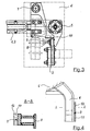
- Mitaueran Farb 8 is shown individually.
- the driver bogie extending downwardly from the bogie 6 in the vertical direction 8 consists, as the section A - A shows, from four flat steel profile parts through Welding are connected to the box-shaped arrangement.
- the spring assembly 11 is here in the form of a plate-like trained rubber elements running. This in turn is a wear plate 12 attached from a wear-resistant Mn-steel alloy. While in braking mode fixed contact the wear plate 12 on the not shown here corresponding stop area
- the brake frame is formed by the spring action of the spring assembly 11 a longitudinal and transverse elastic coupling point, so that the brake frame during braking operation can always take a position optimal load.
- the invention is not limited to the preferred embodiment described above. Rather, constructive modifications thereof are conceivable, even at engage differently embodiment in the claimed by the invention scope.
- the invention is not particularly concerned with the use of an elastomeric body limited as a spring arrangement. This can also, for example, from a spring steel made spring assembly, wherein on the shape of the spring steel, the required Feaersteiftechnik is adaptable depending on the application.
- the shape of the Brake frame is not limited to a rectangular arrangement. Another arrangement is also conceivable, while maintaining the track pitch a synchronous vertical Mobility of the brake magnets ensures.
Landscapes
- Physics & Mathematics (AREA)
- Electromagnetism (AREA)
- Engineering & Computer Science (AREA)
- Mechanical Engineering (AREA)
- Braking Arrangements (AREA)
- Braking Systems And Boosters (AREA)
Claims (10)
- Dispositif de couplage mécanique d'un frein sur rail à un bogie (6) d'un véhicule ferroviaire, ce frein sur rail comprenant des électroaimants de freinage (3a, 3b) affectés à un rail (4) respectif de la voie, dont chacun est disposé à une bride respective de support d'aimant (1a, 1b) pour être levé ou abaissé relativement au rail affecté (4), à un système à entretoises de contrerail étant disposé dans ce dispositif, qui comprend un cadre de frein constitué par lesdites brides de support d'aimants (1a, 1b) et des entretoises de contrerail (2a, 2b), audit cadre de frein retenant lesdits aimants de freinage au-dedans l'écartement de la voie, dans lequel, au plus, plusieurs butées d'entraínement (8a à 8d) sont formés audit bogie (6), qui sont actives le long et à travers du sens de la marche, ces butées d'entraínement coopérant a fin de transmettre l'effort de freinage moyennant des zones de butée correspondantes (10), qui sont formées audit cadre de frein,
caractérisé en ce qu'une plaque d'usure (12), composée d'un matériau dur, est raccordée, via un groupe à ressort (11), à une surface d'arrêt (9) de ladite butée d'entraínement (8) ou à la zone d'arrêt (10) du côté dudit cadre de frein afin de former un endroit de couplage élastique, qui est opératif le long les directions longitudinales et transversales. - Dispositif selon la revendication 1, caractérisé en ce que ledit groupe à ressort (11) est composé d'un matériau élastomère conçu sous forme du type plaque.
- Dispositif selon la revendication 2, caractérisé en ce que ledit groupe à ressort (11) avec ladite plaque d'usure (12) est conçu sous forme d'un élément en caoutchouc/métal.
- Dispositif selon la revendication 1, caractérisé en ce que ledit groupe à ressort (11) est constitué par au moins un ressort de pression composé d'acier à ressorts.
- Dispositif selon la revendication 5, caractérisé en ce que ledit ressort métallique de pression est conçu à la façon d'un ressort à boudin, d'un ressort à lames ou un ressort à disques.
- Dispositif selon la revendication 1, caractérisé en ce que ladite plaque d'usure (12) est faite en un alliage d'acier dur, qui contient une fraction en manganèse.
- Dispositif selon la revendication 1, caractérisé en ce que ladite plaque d'usure (12) est faite en un alliage de laiton.
- Dispositif selon la revendication 1, caractérisé en ce que ledit groupe d'entretoises de contrerail comprend deux entretoises de contrerail (2a, 2b) parallèles, disposées en parallèle l'une à l'autre et espacées l'une de l'autre, qui coopèrent avec lesdites brides de support d'aimants (1a, 1b) afin de former ensemble un cadre de frein rectangulaire.
- Dispositif selon la revendication 7, caractérisé en ce que quatre butées d'entraínement (8a, 8b, 8c, 8d) sont disposées au total, qui portent contre les zones de coin dudit cadre de frein rectangulaire, du côté terminal, audit groupe d'entretoises de contrerail, auxdites butées d'entraínement (8a à 8d) étant disposées en face dudit cadre de frein, en maintenant un jeu longitudinal et transversal.
- Dispositif selon la revendication 1, caractérisé en ce que lesdits électroaimants de freinage (3a, 3b) s'élèvent et s'abaissent via des cylindres acteurs (5) disposés du côté terminal à ladite bride de support d'aimant (1a, 1b) et sont aptes à être exposés aux effets d'un milieu comprimé, dans lequel la position de freinage est achevés par l'abaissement desdits aimants de freinage (3a, 3b) et, en position de desserrage de frein, lesdits aimants de freinage (3a, 3b) coopèrent, de manière positive, avec un moyen de centrage (7) pour l'arrêt.
Priority Applications (1)
| Application Number | Priority Date | Filing Date | Title |
|---|---|---|---|
| DK01969656T DK1315647T3 (da) | 2000-08-28 | 2001-08-28 | Anordning til mekanisk kobling af en skinnebremse på en bogie til et skinneköretöj (bremsekraftmedbringer) |
Applications Claiming Priority (3)
| Application Number | Priority Date | Filing Date | Title |
|---|---|---|---|
| DE10042213 | 2000-08-28 | ||
| DE10042213A DE10042213A1 (de) | 2000-08-28 | 2000-08-28 | Vorrichtung zur mechanischen Kopplung einer Schienenbremse an einem Drehgestell eines Schienenfahrzeuges (Bremskraftmitnehmer) |
| PCT/EP2001/009887 WO2002018190A2 (fr) | 2000-08-28 | 2001-08-28 | Dispositif de couplage mecanique d'un frein sur rail a un boggie d'un vehicule ferroviaire (systeme d'entrainement de force de freinage) |
Publications (2)
| Publication Number | Publication Date |
|---|---|
| EP1315647A2 EP1315647A2 (fr) | 2003-06-04 |
| EP1315647B1 true EP1315647B1 (fr) | 2005-06-15 |
Family
ID=7654048
Family Applications (1)
| Application Number | Title | Priority Date | Filing Date |
|---|---|---|---|
| EP01969656A Expired - Lifetime EP1315647B1 (fr) | 2000-08-28 | 2001-08-28 | Dispositif de couplage mecanique d'un frein sur rail a un boggie d'un vehicule ferroviaire (systeme d'entrainement de force de freinage) |
Country Status (8)
| Country | Link |
|---|---|
| EP (1) | EP1315647B1 (fr) |
| AT (1) | ATE297860T1 (fr) |
| DE (2) | DE10042213A1 (fr) |
| ES (1) | ES2243550T3 (fr) |
| HU (1) | HU228163B1 (fr) |
| NO (1) | NO328451B1 (fr) |
| PT (1) | PT1315647E (fr) |
| WO (1) | WO2002018190A2 (fr) |
Families Citing this family (4)
| Publication number | Priority date | Publication date | Assignee | Title |
|---|---|---|---|---|
| CN102431571B (zh) * | 2011-10-24 | 2014-04-16 | 南车株洲电力机车有限公司 | 一种磁轨制动器连接装置及磁轨制动装置 |
| DE202021103772U1 (de) * | 2021-07-14 | 2022-10-27 | Faiveley Transport Bochum GmbH | Laufwerk für ein Schienenfahrzeug mit einer Magnetschienenbremse und einer Zentriervorrichtung, Magnetschienenbremse und Zentriervorrichtung |
| CN117962952B (zh) * | 2024-02-23 | 2024-08-06 | 中南大学 | 一种磁轨制动器的悬挂机构及磁轨制动器 |
| CN117962946A (zh) * | 2024-03-01 | 2024-05-03 | 中车唐山机车车辆有限公司 | 一种磁轨制动装置的安装装置、转向架及轨道车辆 |
Family Cites Families (5)
| Publication number | Priority date | Publication date | Assignee | Title |
|---|---|---|---|---|
| DE883293C (de) * | 1951-09-16 | 1953-07-16 | Strassenbahnen Hannover Ag | Federnde Aufhaengung fuer Schienenbremsmagnete |
| US2782873A (en) * | 1952-07-31 | 1957-02-26 | Eksjoverkan Ab | Device in electrical rail brakes |
| DE2418636A1 (de) * | 1974-04-18 | 1975-10-30 | Knorr Bremse Gmbh | Zentriereinrichtung fuer schienenbremsmagnete |
| FR2314852A1 (fr) * | 1975-06-18 | 1977-01-14 | Sncf | Systeme de suspension de frein lineaire a courants de foucault pour vehicule ferroviaire |
| DE19732483A1 (de) * | 1997-07-29 | 1999-02-04 | Sab Wabco Bsi Verkehrstechnik | Magnetische Bremseinrichtung für Schienenfahrzeuge |
-
2000
- 2000-08-28 DE DE10042213A patent/DE10042213A1/de not_active Withdrawn
-
2001
- 2001-08-28 ES ES01969656T patent/ES2243550T3/es not_active Expired - Lifetime
- 2001-08-28 PT PT01969656T patent/PT1315647E/pt unknown
- 2001-08-28 DE DE50106535T patent/DE50106535D1/de not_active Expired - Lifetime
- 2001-08-28 AT AT01969656T patent/ATE297860T1/de active
- 2001-08-28 HU HU0300795A patent/HU228163B1/hu not_active IP Right Cessation
- 2001-08-28 WO PCT/EP2001/009887 patent/WO2002018190A2/fr not_active Ceased
- 2001-08-28 EP EP01969656A patent/EP1315647B1/fr not_active Expired - Lifetime
-
2003
- 2003-02-26 NO NO20030904A patent/NO328451B1/no not_active IP Right Cessation
Also Published As
| Publication number | Publication date |
|---|---|
| WO2002018190A3 (fr) | 2002-05-23 |
| ES2243550T3 (es) | 2005-12-01 |
| PT1315647E (pt) | 2005-10-31 |
| HU228163B1 (hu) | 2013-01-28 |
| DE50106535D1 (de) | 2005-07-21 |
| EP1315647A2 (fr) | 2003-06-04 |
| NO328451B1 (no) | 2010-02-22 |
| WO2002018190A2 (fr) | 2002-03-07 |
| HUP0300795A2 (en) | 2003-07-28 |
| DE10042213A1 (de) | 2002-03-21 |
| ATE297860T1 (de) | 2005-07-15 |
| NO20030904D0 (no) | 2003-02-26 |
Similar Documents
| Publication | Publication Date | Title |
|---|---|---|
| EP3253637B1 (fr) | Dispositif de transport pour véhicules ferroviaires | |
| EP0282796A1 (fr) | Coeur de voie pour aiguillages ou croisements | |
| EP3554914B1 (fr) | Dispositif de transport | |
| WO2022144393A1 (fr) | Cadre de sustentation, véhicule, agencement de rails et voie ferrée à sustentation magnétique | |
| EP1315647B1 (fr) | Dispositif de couplage mecanique d'un frein sur rail a un boggie d'un vehicule ferroviaire (systeme d'entrainement de force de freinage) | |
| DE2460159C3 (de) | Laufwerk für Schienenfahrzeuge, insbesondere für fahrbare Oberbaumaschinen | |
| EP3245114A1 (fr) | Véhicule ferroviaire, notamment locomotive | |
| EP3042099B1 (fr) | Ressort de suspension secondaire à butée transversale intégrée | |
| EP2551167A2 (fr) | Agencement de ressort dépendant de la charge | |
| EP0299318B1 (fr) | Train de roulement pour véhicule ferroviaire avec frein de voie magnétique ou à frein à courants de Foucault | |
| CH721424A2 (de) | Einrichtung mit einer Zug- und Stossvorrichtung eines Kupplungssystems für ein Schienenfahrzeug | |
| DE60310112T2 (de) | Magnetschienenbremse | |
| EP0284928B1 (fr) | Dispositif de centrage de rail de roulement pour poste de levage et d'abaissement de voie suspendue électrifiée | |
| EP3655304B1 (fr) | Frein magnétique pour un véhicule ferroviaire avec des branches latérales allongées des pièces polaires | |
| DE19503381C2 (de) | Aufhängung einer Schienenbremse an einem Drehgestell eines Schienenfahrzeuges | |
| EP1897776B1 (fr) | Bogie | |
| DE102015119928A1 (de) | Schmiedehammer | |
| EP0724997A1 (fr) | Suspension d'un frein sur rail, notamment un frein à courant de Foucault à un bogie de véhicule ferroviaire | |
| EP1447297A1 (fr) | Barre d'attelage réglable en longueur, avec fonction de recentrage. | |
| DE19849752B4 (de) | Flurförderzeug mit einem neigbaren Hubgerüst | |
| AT228263B (de) | Wiegenloses Drehgestell | |
| DE3840755C2 (fr) | ||
| DE233212C (fr) | ||
| DE202025103176U1 (de) | Gelenkige Schienenverbindung | |
| EP1364854B1 (fr) | Dispositif pour tenir une traverse |
Legal Events
| Date | Code | Title | Description |
|---|---|---|---|
| PUAI | Public reference made under article 153(3) epc to a published international application that has entered the european phase |
Free format text: ORIGINAL CODE: 0009012 |
|
| 17P | Request for examination filed |
Effective date: 20030328 |
|
| AK | Designated contracting states |
Designated state(s): AT BE CH CY DE DK ES FI FR GB GR IE IT LI LU MC NL PT SE TR |
|
| RIN1 | Information on inventor provided before grant (corrected) |
Inventor name: FRIEDL, ANDREAS Inventor name: SCHMIED, LOTHAR Inventor name: LEHMANN, HENRY |
|
| GRAP | Despatch of communication of intention to grant a patent |
Free format text: ORIGINAL CODE: EPIDOSNIGR1 |
|
| GRAS | Grant fee paid |
Free format text: ORIGINAL CODE: EPIDOSNIGR3 |
|
| GRAA | (expected) grant |
Free format text: ORIGINAL CODE: 0009210 |
|
| AK | Designated contracting states |
Kind code of ref document: B1 Designated state(s): AT BE CH CY DE DK ES FI FR GB GR IE IT LI LU MC NL PT SE TR |
|
| PG25 | Lapsed in a contracting state [announced via postgrant information from national office to epo] |
Ref country code: IE Free format text: LAPSE BECAUSE OF FAILURE TO SUBMIT A TRANSLATION OF THE DESCRIPTION OR TO PAY THE FEE WITHIN THE PRESCRIBED TIME-LIMIT Effective date: 20050615 Ref country code: TR Free format text: LAPSE BECAUSE OF FAILURE TO SUBMIT A TRANSLATION OF THE DESCRIPTION OR TO PAY THE FEE WITHIN THE PRESCRIBED TIME-LIMIT Effective date: 20050615 Ref country code: GB Free format text: LAPSE BECAUSE OF FAILURE TO SUBMIT A TRANSLATION OF THE DESCRIPTION OR TO PAY THE FEE WITHIN THE PRESCRIBED TIME-LIMIT Effective date: 20050615 |
|
| REG | Reference to a national code |
Ref country code: GB Ref legal event code: FG4D Free format text: NOT ENGLISH Ref country code: CH Ref legal event code: EP |
|
| REG | Reference to a national code |
Ref country code: CH Ref legal event code: NV Representative=s name: ISLER & PEDRAZZINI AG |
|
| REF | Corresponds to: |
Ref document number: 50106535 Country of ref document: DE Date of ref document: 20050721 Kind code of ref document: P |
|
| REG | Reference to a national code |
Ref country code: IE Ref legal event code: FG4D Free format text: LANGUAGE OF EP DOCUMENT: GERMAN |
|
| REG | Reference to a national code |
Ref country code: DK Ref legal event code: T3 |
|
| PG25 | Lapsed in a contracting state [announced via postgrant information from national office to epo] |
Ref country code: CY Free format text: LAPSE BECAUSE OF FAILURE TO SUBMIT A TRANSLATION OF THE DESCRIPTION OR TO PAY THE FEE WITHIN THE PRESCRIBED TIME-LIMIT Effective date: 20050828 |
|
| PG25 | Lapsed in a contracting state [announced via postgrant information from national office to epo] |
Ref country code: MC Free format text: LAPSE BECAUSE OF NON-PAYMENT OF DUE FEES Effective date: 20050831 Ref country code: LU Free format text: LAPSE BECAUSE OF NON-PAYMENT OF DUE FEES Effective date: 20050831 |
|
| REG | Reference to a national code |
Ref country code: GR Ref legal event code: EP Ref document number: 20050402487 Country of ref document: GR Ref country code: SE Ref legal event code: TRGR |
|
| REG | Reference to a national code |
Ref country code: PT Ref legal event code: SC4A Effective date: 20050901 |
|
| REG | Reference to a national code |
Ref country code: ES Ref legal event code: FG2A Ref document number: 2243550 Country of ref document: ES Kind code of ref document: T3 |
|
| GBV | Gb: ep patent (uk) treated as always having been void in accordance with gb section 77(7)/1977 [no translation filed] |
Effective date: 20050615 |
|
| REG | Reference to a national code |
Ref country code: IE Ref legal event code: FD4D |
|
| ET | Fr: translation filed | ||
| PLBE | No opposition filed within time limit |
Free format text: ORIGINAL CODE: 0009261 |
|
| STAA | Information on the status of an ep patent application or granted ep patent |
Free format text: STATUS: NO OPPOSITION FILED WITHIN TIME LIMIT |
|
| 26N | No opposition filed |
Effective date: 20060316 |
|
| REG | Reference to a national code |
Ref country code: CH Ref legal event code: PCAR Free format text: ISLER & PEDRAZZINI AG;POSTFACH 1772;8027 ZUERICH (CH) |
|
| PGFP | Annual fee paid to national office [announced via postgrant information from national office to epo] |
Ref country code: GR Payment date: 20140820 Year of fee payment: 14 |
|
| PGFP | Annual fee paid to national office [announced via postgrant information from national office to epo] |
Ref country code: PT Payment date: 20140228 Year of fee payment: 14 Ref country code: IT Payment date: 20140828 Year of fee payment: 14 |
|
| REG | Reference to a national code |
Ref country code: FR Ref legal event code: PLFP Year of fee payment: 15 |
|
| PGFP | Annual fee paid to national office [announced via postgrant information from national office to epo] |
Ref country code: NL Payment date: 20150824 Year of fee payment: 15 |
|
| PGFP | Annual fee paid to national office [announced via postgrant information from national office to epo] |
Ref country code: DE Payment date: 20150820 Year of fee payment: 15 Ref country code: DK Payment date: 20150825 Year of fee payment: 15 Ref country code: ES Payment date: 20150825 Year of fee payment: 15 Ref country code: FI Payment date: 20150820 Year of fee payment: 15 Ref country code: CH Payment date: 20150824 Year of fee payment: 15 |
|
| PGFP | Annual fee paid to national office [announced via postgrant information from national office to epo] |
Ref country code: FR Payment date: 20150824 Year of fee payment: 15 Ref country code: AT Payment date: 20150820 Year of fee payment: 15 Ref country code: BE Payment date: 20150820 Year of fee payment: 15 Ref country code: SE Payment date: 20150824 Year of fee payment: 15 |
|
| REG | Reference to a national code |
Ref country code: PT Ref legal event code: MM4A Free format text: LAPSE DUE TO NON-PAYMENT OF FEES Effective date: 20160229 |
|
| PG25 | Lapsed in a contracting state [announced via postgrant information from national office to epo] |
Ref country code: IT Free format text: LAPSE BECAUSE OF NON-PAYMENT OF DUE FEES Effective date: 20150828 |
|
| PG25 | Lapsed in a contracting state [announced via postgrant information from national office to epo] |
Ref country code: PT Free format text: LAPSE BECAUSE OF NON-PAYMENT OF DUE FEES Effective date: 20160229 Ref country code: GR Free format text: LAPSE BECAUSE OF NON-PAYMENT OF DUE FEES Effective date: 20160303 |
|
| REG | Reference to a national code |
Ref country code: GR Ref legal event code: ML Ref document number: 20050402487 Country of ref document: GR Effective date: 20160303 |
|
| PG25 | Lapsed in a contracting state [announced via postgrant information from national office to epo] |
Ref country code: BE Free format text: LAPSE BECAUSE OF NON-PAYMENT OF DUE FEES Effective date: 20160831 |
|
| REG | Reference to a national code |
Ref country code: DE Ref legal event code: R119 Ref document number: 50106535 Country of ref document: DE |
|
| REG | Reference to a national code |
Ref country code: DK Ref legal event code: EBP Effective date: 20160831 |
|
| REG | Reference to a national code |
Ref country code: SE Ref legal event code: EUG |
|
| REG | Reference to a national code |
Ref country code: CH Ref legal event code: PL |
|
| REG | Reference to a national code |
Ref country code: NL Ref legal event code: MM Effective date: 20160901 |
|
| REG | Reference to a national code |
Ref country code: AT Ref legal event code: MM01 Ref document number: 297860 Country of ref document: AT Kind code of ref document: T Effective date: 20160828 |
|
| PG25 | Lapsed in a contracting state [announced via postgrant information from national office to epo] |
Ref country code: FI Free format text: LAPSE BECAUSE OF NON-PAYMENT OF DUE FEES Effective date: 20160828 Ref country code: CH Free format text: LAPSE BECAUSE OF NON-PAYMENT OF DUE FEES Effective date: 20160831 Ref country code: LI Free format text: LAPSE BECAUSE OF NON-PAYMENT OF DUE FEES Effective date: 20160831 Ref country code: SE Free format text: LAPSE BECAUSE OF NON-PAYMENT OF DUE FEES Effective date: 20160829 |
|
| REG | Reference to a national code |
Ref country code: FR Ref legal event code: ST Effective date: 20170428 |
|
| PG25 | Lapsed in a contracting state [announced via postgrant information from national office to epo] |
Ref country code: AT Free format text: LAPSE BECAUSE OF NON-PAYMENT OF DUE FEES Effective date: 20160828 |
|
| PG25 | Lapsed in a contracting state [announced via postgrant information from national office to epo] |
Ref country code: NL Free format text: LAPSE BECAUSE OF NON-PAYMENT OF DUE FEES Effective date: 20160901 |
|
| PG25 | Lapsed in a contracting state [announced via postgrant information from national office to epo] |
Ref country code: FR Free format text: LAPSE BECAUSE OF NON-PAYMENT OF DUE FEES Effective date: 20160831 Ref country code: DK Free format text: LAPSE BECAUSE OF NON-PAYMENT OF DUE FEES Effective date: 20160831 Ref country code: DE Free format text: LAPSE BECAUSE OF NON-PAYMENT OF DUE FEES Effective date: 20170301 |
|
| PG25 | Lapsed in a contracting state [announced via postgrant information from national office to epo] |
Ref country code: ES Free format text: LAPSE BECAUSE OF NON-PAYMENT OF DUE FEES Effective date: 20160829 |
|
| REG | Reference to a national code |
Ref country code: ES Ref legal event code: FD2A Effective date: 20181126 |