EP1316331A1 - Procédé pour déterminer la capacité d'adsorption dans un dispositif pour éliminer le dioxyde de carbone et le dispositif associé - Google Patents
Procédé pour déterminer la capacité d'adsorption dans un dispositif pour éliminer le dioxyde de carbone et le dispositif associé Download PDFInfo
- Publication number
- EP1316331A1 EP1316331A1 EP02258125A EP02258125A EP1316331A1 EP 1316331 A1 EP1316331 A1 EP 1316331A1 EP 02258125 A EP02258125 A EP 02258125A EP 02258125 A EP02258125 A EP 02258125A EP 1316331 A1 EP1316331 A1 EP 1316331A1
- Authority
- EP
- European Patent Office
- Prior art keywords
- agent material
- carbon dioxide
- temperature
- determined
- determining
- Prior art date
- Legal status (The legal status is an assumption and is not a legal conclusion. Google has not performed a legal analysis and makes no representation as to the accuracy of the status listed.)
- Granted
Links
- CURLTUGMZLYLDI-UHFFFAOYSA-N Carbon dioxide Chemical compound O=C=O CURLTUGMZLYLDI-UHFFFAOYSA-N 0.000 title claims abstract description 168
- 229910002092 carbon dioxide Inorganic materials 0.000 title claims abstract description 85
- 239000001569 carbon dioxide Substances 0.000 title claims abstract description 83
- 238000000034 method Methods 0.000 title claims abstract description 19
- 238000001179 sorption measurement Methods 0.000 title 1
- 239000000463 material Substances 0.000 claims abstract description 141
- 239000003795 chemical substances by application Substances 0.000 claims abstract description 137
- 239000007789 gas Substances 0.000 claims abstract description 87
- QVGXLLKOCUKJST-UHFFFAOYSA-N atomic oxygen Chemical compound [O] QVGXLLKOCUKJST-UHFFFAOYSA-N 0.000 claims abstract description 28
- 239000001301 oxygen Substances 0.000 claims abstract description 28
- 229910052760 oxygen Inorganic materials 0.000 claims abstract description 28
- 239000000203 mixture Substances 0.000 claims abstract description 9
- 238000002347 injection Methods 0.000 claims abstract description 7
- 239000007924 injection Substances 0.000 claims abstract description 7
- 230000004044 response Effects 0.000 claims description 11
- 238000011144 upstream manufacturing Methods 0.000 claims description 10
- 230000001052 transient effect Effects 0.000 claims description 9
- XLYOFNOQVPJJNP-UHFFFAOYSA-N water Substances O XLYOFNOQVPJJNP-UHFFFAOYSA-N 0.000 claims description 7
- 230000007704 transition Effects 0.000 claims description 5
- 238000001514 detection method Methods 0.000 claims description 3
- 230000029058 respiratory gaseous exchange Effects 0.000 abstract description 17
- 238000006243 chemical reaction Methods 0.000 description 18
- IJGRMHOSHXDMSA-UHFFFAOYSA-N Atomic nitrogen Chemical compound N#N IJGRMHOSHXDMSA-UHFFFAOYSA-N 0.000 description 12
- 238000010168 coupling process Methods 0.000 description 7
- 238000005859 coupling reaction Methods 0.000 description 7
- 230000009189 diving Effects 0.000 description 6
- 229910052757 nitrogen Inorganic materials 0.000 description 6
- VTYYLEPIZMXCLO-UHFFFAOYSA-L Calcium carbonate Chemical compound [Ca+2].[O-]C([O-])=O VTYYLEPIZMXCLO-UHFFFAOYSA-L 0.000 description 4
- 238000001816 cooling Methods 0.000 description 4
- 230000003134 recirculating effect Effects 0.000 description 4
- 230000002028 premature Effects 0.000 description 3
- HUAUNKAZQWMVFY-UHFFFAOYSA-M sodium;oxocalcium;hydroxide Chemical compound [OH-].[Na+].[Ca]=O HUAUNKAZQWMVFY-UHFFFAOYSA-M 0.000 description 3
- 241000239290 Araneae Species 0.000 description 2
- 239000011149 active material Substances 0.000 description 2
- 229910000019 calcium carbonate Inorganic materials 0.000 description 2
- AXCZMVOFGPJBDE-UHFFFAOYSA-L calcium dihydroxide Chemical compound [OH-].[OH-].[Ca+2] AXCZMVOFGPJBDE-UHFFFAOYSA-L 0.000 description 2
- 239000000920 calcium hydroxide Substances 0.000 description 2
- 229910001861 calcium hydroxide Inorganic materials 0.000 description 2
- -1 carbonate compound Chemical class 0.000 description 2
- 238000013461 design Methods 0.000 description 2
- 239000008187 granular material Substances 0.000 description 2
- 210000004072 lung Anatomy 0.000 description 2
- 231100000331 toxic Toxicity 0.000 description 2
- 230000002588 toxic effect Effects 0.000 description 2
- MYMOFIZGZYHOMD-UHFFFAOYSA-N Dioxygen Chemical compound O=O MYMOFIZGZYHOMD-UHFFFAOYSA-N 0.000 description 1
- 230000009471 action Effects 0.000 description 1
- 230000004888 barrier function Effects 0.000 description 1
- 238000009529 body temperature measurement Methods 0.000 description 1
- 239000011575 calcium Substances 0.000 description 1
- 238000002485 combustion reaction Methods 0.000 description 1
- 230000008878 coupling Effects 0.000 description 1
- 238000010586 diagram Methods 0.000 description 1
- 239000003085 diluting agent Substances 0.000 description 1
- 230000000694 effects Effects 0.000 description 1
- XLYOFNOQVPJJNP-ZSJDYOACSA-N heavy water Substances [2H]O[2H] XLYOFNOQVPJJNP-ZSJDYOACSA-N 0.000 description 1
- 239000001307 helium Substances 0.000 description 1
- 229910052734 helium Inorganic materials 0.000 description 1
- SWQJXJOGLNCZEY-UHFFFAOYSA-N helium atom Chemical compound [He] SWQJXJOGLNCZEY-UHFFFAOYSA-N 0.000 description 1
- 230000001788 irregular Effects 0.000 description 1
- 239000012528 membrane Substances 0.000 description 1
- 238000012986 modification Methods 0.000 description 1
- 230000004048 modification Effects 0.000 description 1
- 238000012544 monitoring process Methods 0.000 description 1
- 230000001473 noxious effect Effects 0.000 description 1
- 238000012545 processing Methods 0.000 description 1
- 230000009257 reactivity Effects 0.000 description 1
- 230000009467 reduction Effects 0.000 description 1
- 230000000630 rising effect Effects 0.000 description 1
- 239000000523 sample Substances 0.000 description 1
- 238000007789 sealing Methods 0.000 description 1
- 239000004065 semiconductor Substances 0.000 description 1
- 239000007787 solid Substances 0.000 description 1
Images
Classifications
-
- B—PERFORMING OPERATIONS; TRANSPORTING
- B01—PHYSICAL OR CHEMICAL PROCESSES OR APPARATUS IN GENERAL
- B01D—SEPARATION
- B01D53/00—Separation of gases or vapours; Recovering vapours of volatile solvents from gases; Chemical or biological purification of waste gases, e.g. engine exhaust gases, smoke, fumes, flue gases, aerosols
- B01D53/02—Separation of gases or vapours; Recovering vapours of volatile solvents from gases; Chemical or biological purification of waste gases, e.g. engine exhaust gases, smoke, fumes, flue gases, aerosols by adsorption, e.g. preparative gas chromatography
- B01D53/04—Separation of gases or vapours; Recovering vapours of volatile solvents from gases; Chemical or biological purification of waste gases, e.g. engine exhaust gases, smoke, fumes, flue gases, aerosols by adsorption, e.g. preparative gas chromatography with stationary adsorbents
- B01D53/0407—Constructional details of adsorbing systems
- B01D53/0438—Cooling or heating systems
-
- A—HUMAN NECESSITIES
- A62—LIFE-SAVING; FIRE-FIGHTING
- A62B—DEVICES, APPARATUS OR METHODS FOR LIFE-SAVING
- A62B19/00—Cartridges with absorbing substances for respiratory apparatus
-
- A—HUMAN NECESSITIES
- A62—LIFE-SAVING; FIRE-FIGHTING
- A62B—DEVICES, APPARATUS OR METHODS FOR LIFE-SAVING
- A62B9/00—Component parts for respiratory or breathing apparatus
- A62B9/006—Indicators or warning devices, e.g. of low pressure, contamination
-
- B—PERFORMING OPERATIONS; TRANSPORTING
- B63—SHIPS OR OTHER WATERBORNE VESSELS; RELATED EQUIPMENT
- B63C—LAUNCHING, HAULING-OUT, OR DRY-DOCKING OF VESSELS; LIFE-SAVING IN WATER; EQUIPMENT FOR DWELLING OR WORKING UNDER WATER; MEANS FOR SALVAGING OR SEARCHING FOR UNDERWATER OBJECTS
- B63C11/00—Equipment for dwelling or working underwater; Means for searching for underwater objects
- B63C11/02—Divers' equipment
- B63C11/18—Air supply
- B63C11/22—Air supply carried by diver
- B63C11/24—Air supply carried by diver in closed circulation
-
- B—PERFORMING OPERATIONS; TRANSPORTING
- B01—PHYSICAL OR CHEMICAL PROCESSES OR APPARATUS IN GENERAL
- B01D—SEPARATION
- B01D2256/00—Main component in the product gas stream after treatment
- B01D2256/12—Oxygen
-
- B—PERFORMING OPERATIONS; TRANSPORTING
- B01—PHYSICAL OR CHEMICAL PROCESSES OR APPARATUS IN GENERAL
- B01D—SEPARATION
- B01D2257/00—Components to be removed
- B01D2257/50—Carbon oxides
- B01D2257/504—Carbon dioxide
-
- B—PERFORMING OPERATIONS; TRANSPORTING
- B01—PHYSICAL OR CHEMICAL PROCESSES OR APPARATUS IN GENERAL
- B01D—SEPARATION
- B01D2259/00—Type of treatment
- B01D2259/45—Gas separation or purification devices adapted for specific applications
- B01D2259/4533—Gas separation or purification devices adapted for specific applications for medical purposes
-
- B—PERFORMING OPERATIONS; TRANSPORTING
- B01—PHYSICAL OR CHEMICAL PROCESSES OR APPARATUS IN GENERAL
- B01D—SEPARATION
- B01D53/00—Separation of gases or vapours; Recovering vapours of volatile solvents from gases; Chemical or biological purification of waste gases, e.g. engine exhaust gases, smoke, fumes, flue gases, aerosols
- B01D53/02—Separation of gases or vapours; Recovering vapours of volatile solvents from gases; Chemical or biological purification of waste gases, e.g. engine exhaust gases, smoke, fumes, flue gases, aerosols by adsorption, e.g. preparative gas chromatography
- B01D53/04—Separation of gases or vapours; Recovering vapours of volatile solvents from gases; Chemical or biological purification of waste gases, e.g. engine exhaust gases, smoke, fumes, flue gases, aerosols by adsorption, e.g. preparative gas chromatography with stationary adsorbents
- B01D53/0407—Constructional details of adsorbing systems
- B01D53/0415—Beds in cartridges
-
- Y—GENERAL TAGGING OF NEW TECHNOLOGICAL DEVELOPMENTS; GENERAL TAGGING OF CROSS-SECTIONAL TECHNOLOGIES SPANNING OVER SEVERAL SECTIONS OF THE IPC; TECHNICAL SUBJECTS COVERED BY FORMER USPC CROSS-REFERENCE ART COLLECTIONS [XRACs] AND DIGESTS
- Y02—TECHNOLOGIES OR APPLICATIONS FOR MITIGATION OR ADAPTATION AGAINST CLIMATE CHANGE
- Y02C—CAPTURE, STORAGE, SEQUESTRATION OR DISPOSAL OF GREENHOUSE GASES [GHG]
- Y02C20/00—Capture or disposal of greenhouse gases
- Y02C20/40—Capture or disposal of greenhouse gases of CO2
Definitions
- the present invention relates to carbon dioxide scrubbers and in particular concerns carbon dioxide scrubbers for breathing apparatus such as may be used for underwater diving or in other hostile environments in which a user may need a supply of breathable gas.
- Such uses include fire fighting where the atmosphere may be heavily polluted with combustion products and noxious gases, other industrial environments where the atmosphere may be polluted or otherwise unbreathable, or at high altitude where the atmosphere itself is too thin or effectively non-existent.
- the term re-circulating gas self-contained breathing apparatus used herein refers to both closed circuit and semi-closed circuit re-breathers and any other type of re-breathing apparatus in which at least a portion of the exhaled gas is recirculated.
- the most widely used self-contained breathing apparatus comprises a rigid container within which is housed a supply of compressed air which is allowed out of the container via a high pressure or first stage regulator and directed through a flexible hose to a mouthpiece containing a demand valve including a second stage regulator which acts automatically to open and close as the diver inhales and exhales.
- Such systems are known as open-circuit breathing apparatus because exhaled gas is allowed to pass directly out into the marine environment so that a stream of bubbles is emitted upon each exhalation.
- the compressed gas breathed from the gas container is air a large proportion of the exhaled gas will constitute nitrogen which is present in air in an approximate ratio of 4:1 with oxygen as is well known.
- 80% of the air which is breathed by the diver, and therefore 80% of the content of the compressed air container, or air bottle comprises little more than a vehicle for the oxygen some of which is converted to carbon dioxide during its residence in the lung.
- 80% of the breathed gas is not really needed by the body except to dilute the oxygen. It is not possible to breathe pure oxygen below 10 m since at higher pressures oxygen is toxic.
- US Patent 4 964 404 describes an improved such mixed gas breathing apparatus in which a container for exhaled gas (the so-called counterlung) is formed in two parts, a first part communicating with a hose leading from a mouthpiece to a carbon dioxide removal filter, and a second part in the line between the carbon dioxide removal filter and the mouthpiece.
- the carbon dioxide removal filter in the system described in US 3 556 098 includes a chamber housing oxygen partial pressure sensors used to detect the oxygen content in the exhaled gas and to reinstate the oxygen balance by introducing oxygen through a valve controlled indirectly by the sensors.
- the carbon dioxide removal filter comprises a filter bed of re-agent material housed between circular permeable barriers in a cylindrical container having a central axial member.
- the carbon dioxide removal filter comprises a filter bed of re-agent material housed within a cylindrical container within the recirculating circuit to safely remove exhaled carbon dioxide.
- the re-agent material prevents the exhaled carbon dioxide passing through the filter and back to the user's lungs.
- breakthrough occurs and carbon dioxide passes through the filter and if the user continues to breathe through the breathing apparatus the carbon dioxide concentration will increase until it reaches toxic levels. Proposals have been made for detecting the exhaustion of the carbon dioxide re-agent material by directly measuring the carbon dioxide concentration of the recirculating gases.
- the said apparatus comprising at least two temperature sensors disposed in or adjacent to the said re-agent material for measuring the temperature difference between at least two locations during carbon dioxide removal, and means for determining the remaining carbon dioxide absorbing capacity of the said re-agent material in accordance with the measured temperature difference the said at least two sensors.
- the temperature sensors measure the temperature increase due to the exothermic chemical reaction within the re-agent material due to carbon dioxide gas being converted into a solid carbonate compound by the action of the re-agent material removing the carbon dioxide gas from the recirculating gas flow.
- the heat that is generated by this exothermic reaction causes a local temperature rise.
- the inventors have found that the temperature of the re-agent material increases in a substantially linear manner through the body of the re-agent material until it reaches a substantially uniform operating temperature. It is to be appreciated that the operating temperature varies with scrubber design, the type of re-agent material, ambient temperature, the density of the re-agent material and the breathing rate of the user.
- the progression of the temperature rise through the body of the re-agent material occurs in the gas flow direction and may be considered to represent a "warm temperature front" or a reaction front as it progresses from the inlet end to the outlet end of the re-agent material.
- the re-agent material that is to say converted to a carbonate compound
- the material begins to cool.
- the re-agent material that is first exposed to the carbon dioxide is used, or consumed, first and the material that is exposed last is the last to be consumed.
- cooling of the re-agent material also progresses through the body of the material in the gas flow direction in a linear manner.
- the progression of the temperature reduction through the body of the re-agent material may be considered to represent a "cold front".
- the above aspect of the invention measures the activity of the chemical reaction within the re-agent material to determine the remaining absorbing capacity of the material and therefore the remaining life of the filter cartridge before exhaustion of the re-agent material and carbon dioxide breakthrough.
- This aspect of the invention provides a simple and relatively inexpensive apparatus for providing a pre-emptive warning of so-called CO 2 breakthrough by measuring the proportion of re-agent material that is exhausted and thereby the remaining carbon dioxide absorbing capacity of the cartridge.
- the apparatus is not affected by humidity, gas composition or pressure since it does not measure carbon dioxide directly.
- the temperature sensors have very low power requirements and in particular the sensors do not require absolute calibration since all temperature measurements are relative, that is to say, it is the temperature difference between sensors that is important and not the absolute temperature between the parts of the re-agent material where the sensors are located.
- the sensors are disposed in at least a first direction which corresponds to the direction of the gas flow through the re-agent material, thereby to determine the temperature gradient in the said flow direction.
- the exothermic reaction occurs when the carbon dioxide in the recirculating gas flow first comes into contact with active re-agent material. Initially, the warm reaction front moves along the length of the filter cartridge in the direction of the gas flow in the cartridge. In this way as the reaction front moves along the length of the cartridge the temperature profile or gradient that exists in the re-agent material due to the reaction also moves in the direction of the gas flow.
- a plurality of temperature sensors are distributed throughout the said re-agent material in the gas flow direction for determining the temperature distribution in the said re-agent material, in the gas flow direction, during carbon dioxide removal.
- the apparatus further comprises a means for comparing the said detected temperature distribution in the re-agent material with a respective pre-determined temperature distribution characteristic for the said re-agent material, and an alerting means which is actuated in response to detected differences between the said detected distribution and the said pre-determined characteristic.
- the apparatus further comprises means for determining when the detected temperature difference between at least a pair of temperature sensors exceeds a pre-determined maximum value.
- the apparatus further comprises a pressure sensor and a means for selecting the said pair of temperature sensors from a plurality of temperature sensors in the re-agent material in accordance with the pressure measured by the said pressure sensor.
- the apparatus further comprises means for determining the said pre-determined maximum temperature difference in accordance with the pressure measured by the said pressure sensor.
- the said alerting means is actuated in response to the said detected temperature difference exceeding the said pre-determined value.
- the said alerting means is actuated in response to a detected difference between a detected transient temperature distribution in the said re-agent material and a pre-determined transient temperature distribution characteristic for the said re-agent material.
- transient temperature distribution refers to the temperature distribution in the re-agent material immediately after the commencement of the removal of carbon dioxide gas and prior to the re-agent material being heated to a steady state operating temperature by the exothermic reaction.
- the said remaining carbon dioxide absorbing capacity is determined in accordance with the steady state temperature distribution in the re-agent material.
- steady state temperature distribution refers to the temperature distribution in the re-agent material once the re-agent material has been heated to a steady state operating temperature by the exothermic reaction.
- the steady state temperature distribution may vary with time due to cooling of the non-active spent re-agent material as described above.
- the said steady state temperature distribution comprises an upstream region of increasing temperature in the flow direction and a region downstream thereof of substantially constant and elevated temperature
- the said means for determining the remaining carbon dioxide content comprises means for identifying the position of transition in the said re-agent material between the said upstream and downstream regions.
- the said remaining carbon dioxide absorbing capacity is preferably determined in accordance with the position of the drop in measured temperature in the re-agent material.
- the said temperature sensors may be distributed throughout the said re-agent material for determining the three dimensional temperature profile of the said re-agent material generated during carbon dioxide removal.
- This can also be used to identify so called "channelling", that is to say canalising of the gas flow along preferred channels in the cartridge in the direction of the gas flow.
- the said alerting means may be actuated in response to the detection of a preferred channelled gas flow path in the re-agent material. This readily enables the user to be alerted where premature breakthrough will occur through canalising of the gas flow through the re-agent material.
- the apparatus further comprises means for receiving a water depth sensor signal and means for applying a safety factor to the determined remaining absorbing capacity of the said re-agent material in accordance with the said depth signal.
- a safety factor for the duration of the remaining active material in the cartridge in accordance with the depth of the apparatus when used in a diving embodiment. For example, the safety margin can be increased when the depth is increased.
- the said determining means and/or the said depth signal receiving means is/are incorporated in a microprocessor.
- the signals from the temperature sensors and/or depths sensor can be readily processed in a microprocessor to determine the estimated remaining life of the re-agent material in the filter cartridge.
- the apparatus may further comprise a display means for displaying information relating to the determined remaining carbon dioxide absorbing capacity of the said re-agent material.
- the user can be readily provided with information relating to the estimated remaining life of the cartridge.
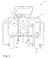
- self-contained re-breather apparatus generally indicated with the reference numeral 11 comprises a closed circuit leading from a mouthpiece 12 along an air hose 13 within which is a unidirectional valve indicated schematically 15 and connected to an exhaled-gas counterlung 16 by a T-coupling 17.
- the reconditioned gas is drawn from the unit 19 via an air hose 23 and delivered to a second counterlung 24 in the form of a flexible sac joined to the hose 23 by another T-coupling 25 which, like the T-coupling 17 is swivelable to allow free movement of the air hose during use and for ease of assembly.
- T-coupling 25 From the T-coupling 25 a breathing hose 26 leads to the mouthpiece 12 via a further unidirectional valve 27 shown schematically in Figure 1.
- a reservoir 69 of diluent gas is directly connected to a control valve 79 on the counterlung 24.
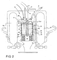
- the exhaled air treatment apparatus generally indicated 19 comprises an upright cylindrical container 32 having an inner cartridge 39, which will be described in more detail below, a lower inlet port 33 with a rigid inlet duct 34 extending parallel to the axis of the container 32 and having a releasable coupling 35 for connection to the air hose 18 leading from the T-coupling 17.
- a lower chamber 36 into which the port 33 opens and which houses the inner cartridge 39.
- the cartridge 39 contains a granular material, such as soda lime, which absorbs carbon dioxide.
- TM Sofliolime
- a plurality of temperature sensors 70 are distributed in the cartridge 39 on the inner surface of the cartridge cylinder wall 72 and also along a central stem 100.
- the stem 100 passes through the granular re-agent material contained in the cartridge 39 for securing the spiders 37, 38 and membranes 49, 50 to the cartridge.
- the temperature sensors 70 on the cylinder 72 and stem 100 are aligned with one another in the axial direction of the cylinder and spaced by equal intervals in the axial direction of the cylinder, for instance 1 to 3 cm intervals.
- the temperature sensors are electrically connected to a microprocessor unit 76 in the upper chamber 40 of the container so that the output signals from the respective temperature sensors can be input to the microprocessor for determining the temperature distribution in the granular re-agent material.
- a microprocessor unit 76 in the upper chamber 40 of the container so that the output signals from the respective temperature sensors can be input to the microprocessor for determining the temperature distribution in the granular re-agent material.
- the electrical connection of the temperature sensors to the microprocessor is shown schematically and represented by lines 77.
- the sensors 70 are semi conductor temperature sensors.
- the microprocessor is suitably programmed to determine the temperature gradient in the re-agent material due to carbon dioxide removal when re-circulating gas flows through the container from the lower chamber 36 to the upper chamber 40 as indicated by the direction of arrow 78 in Figure 2.
- the microprocessor is further programmed to determine the position of the exothermic carbon dioxide absorbing reaction front (warm front) in the granular material by processing the temperature distribution data obtained from the sensors 70, to compare that data with respective pre-determined characteristics for a correctly functioning scrubber so that any deviations can be identified and the user can be warned and predict the remaining carbon dioxide absorbing capacity of the re-agent material in accordance with the temperature distribution and/or temperature gradients present in the re-agent material.
- the microprocessor is further programmed to monitor the progress of the reaction front as it progresses through the re-agent material in the cartridge 39 in the direction of the gas flow 78. When the reaction front reaches and/or passes a predetermined position in the cartridge a signal is generated by the microprocessor to provide an output signal on line 79 to an indicator display 80 ( Figure 1) for warning the user of the proportion of active re-agent material remaining in the cartridge.
- the microprocessor is also programmed to determine the area of carbon dioxide reactivity and predict the remaining carbon dioxide absorbing capacity of the re-agent material in accordance with the temperature distribution and/or temperature gradients present in the re-agent material.
- the microprocessor is further programmed to monitor the progress of the cooling of the re-agent material along the length of the cartridge 39 in the direction of the gas flow 78. For instance, when a sensor in a predetermined position experiences cooling to a predetermined temperature below the temperature of the sensors in the warmest part of the active material, a signal is generated by the microprocessor to provide an output signal on line 79 to an indicator display 80 ( Figure 1) for alerting the user to the proportion of active re-agent material remaining in the cartridge.
- the warning signal may be in the form of flashing lights (LEDs) on the display or alternatively or additionally it may compromise an audible or vibration alert. Several such warning signals may be generated prior to breakthrough, for instance as the amount of active re-agent material is reduced further and the subsequent temperature sensors cool, the positions of which have been pre-determined.
- the microprocessor is also programmed to recognise channelling of the gas flow through a preferred path in the re-agent material so that the user may be alerted to the possibility that premature breakthrough could occur if this is detected.
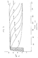
- the invention can be readily understood by referring to the experimentally derived time domain temperature characteristics of Figure 3 for eight equally spaced temperature sensors positioned along the central stem 100 and aligned axially in the gas flow direction in a body of re-agent material contained within the cartridge 39.
- the re-agent material heats up in a substantially linear manner, that is to say in the first 20 minutes of operation the first temperature sensor 101 begins to record an increase in temperature followed by the next sensor 102, which is downstream of the first, then followed by the remaining sensors until eventually the majority of the body re-agent material is heated to substantially the same temperature.
- the re-agent material is heated in a linear manner with each subsequent sensor in the gas flow direction recording a temperature which lags the temperature of an adjacent upstream sensor by about 120 seconds.
- this transition is analogous to a warm reaction front moving from the inlet end to the outlet end of the re-agent material.
- the first sensor 101 begins to record a drop in temperature due to the exhaustion of the re-agent material in the region of the sensor.
- the re-agent material cools in a linear manner as the calcium hydroxide is slowly converted to calcium carbonate.
- the re-agent material cools in a substantially linear manner, that is to say after a short period the first temperature sensor 101 begins to record a decrease in temperature followed by the next sensor 102, then followed by the remaining sensors until eventually the final sensor 108 begins to cools and carbon dioxide breakthrough occurs.
- the temperature characteristic shown in Figure 3 can be compared with a pre-determined temperature characteristic for the canister design.
- This is particularly useful for alerting the user to potential problems with the canister or re-agent material at the onset of use since the pattern of the transient temperature distribution can be monitored and compared with a respective pre-determined distribution.
- channelling may be detected if the sensors do not heat up sequentially as expected with one or more downstream sensors recording higher temperatures than one or more sensors upstream thereof or the upstream sensor do not heat up at all.
- An appropriate signal may be generated to warn the diver of the remaining life of the re-agent material when say sensor 107 records a temperature which is 5 degrees C less than sensor 108, for example, or when sensor 106 is 5 degrees C less than 108 if a greater warning period is require or if the diver is at a greater depth.
- sensor 107 records a temperature which is 5 degrees C less than sensor 108, for example, or when sensor 106 is 5 degrees C less than 108 if a greater warning period is require or if the diver is at a greater depth.
- the breathing apparatus can be a so-called "semi-closed circuit" rebreather apparatus where the injected gas is one that is suitable for direct breathing at a determined depth.
- the injected gas is one that is suitable for direct breathing at a determined depth.
- an appropriate gas is 50% oxygen, 50% nitrogen, for a 40m dive depth an appropriate gas is 28% oxygen, 62% nitrogen.
- a mixture of oxygen, nitrogen and helium is appropriate.
- the different gasses are mixed directly with oxygen prior to diving, independently of the rebreather apparatus, so that separate reservoirs 20 and 69 are not required.
- the temperature sensors may be located on the central stem only, on a probe that extends into the re-agent material in the region of the central stem, on the inner side of the cylindrical sidewall only or on the surface of an intermediate cylindrical sidewall positioned between the stem and the outer sidewall.
Landscapes
- Health & Medical Sciences (AREA)
- General Health & Medical Sciences (AREA)
- Pulmonology (AREA)
- Business, Economics & Management (AREA)
- Engineering & Computer Science (AREA)
- Emergency Management (AREA)
- Chemical & Material Sciences (AREA)
- Mechanical Engineering (AREA)
- Ocean & Marine Engineering (AREA)
- Analytical Chemistry (AREA)
- General Chemical & Material Sciences (AREA)
- Oil, Petroleum & Natural Gas (AREA)
- Chemical Kinetics & Catalysis (AREA)
- Gas Separation By Absorption (AREA)
Applications Claiming Priority (2)
| Application Number | Priority Date | Filing Date | Title |
|---|---|---|---|
| GB0128732A GB2382572B (en) | 2001-11-30 | 2001-11-30 | Apparatus for a carbon dioxide scrubber and method therefor |
| GB0128732 | 2001-11-30 |
Publications (2)
| Publication Number | Publication Date |
|---|---|
| EP1316331A1 true EP1316331A1 (fr) | 2003-06-04 |
| EP1316331B1 EP1316331B1 (fr) | 2007-07-11 |
Family
ID=9926775
Family Applications (1)
| Application Number | Title | Priority Date | Filing Date |
|---|---|---|---|
| EP02258125A Expired - Lifetime EP1316331B1 (fr) | 2001-11-30 | 2002-11-26 | Procédé pour déterminer la capacité d'adsorption dans un dispositif pour éliminer le dioxyde de carbone et le dispositif associé |
Country Status (3)
| Country | Link |
|---|---|
| EP (1) | EP1316331B1 (fr) |
| DE (1) | DE60221087T2 (fr) |
| GB (1) | GB2382572B (fr) |
Cited By (7)
| Publication number | Priority date | Publication date | Assignee | Title |
|---|---|---|---|---|
| EP1911671A1 (fr) * | 2006-09-22 | 2008-04-16 | Gueorgui Todorov | Appareil de plongée en circuit (rebreather) et appareil de plongée à air comprimé (scuba) dotés d'un entraînement autonome et utilisation de différents mélanges de gaz inerte |
| GR1006177B (el) * | 2007-11-20 | 2008-12-02 | Αναργυρος Αναργυρου | Διαταξη μετρησης χρονου ληξης φιλτρων προσωπιδων αεριων και φιλτρων συλλογικης προστασιας |
| WO2014139880A1 (fr) * | 2013-03-13 | 2014-09-18 | Eblatas | Recycleur a adsorption de co2 |
| EP3345674A4 (fr) * | 2015-08-31 | 2019-03-20 | Hitachi Chemical Co., Ltd. | Équipement de traitement de gaz d'échappement et procédé d'estimation d'état de détérioration de matériau de capture de gaz |
| KR20210019527A (ko) * | 2018-12-14 | 2021-02-22 | "아쿠아브리덜" 엘엘씨 | 수중 잠수를 위한 폐쇄 사이클의 개별 자급식 호흡 장치 |
| EP4299160A1 (fr) | 2022-07-01 | 2024-01-03 | Institut Für Luft- Und Kältetechnik gGmbh | Ensemble capteur et procédé de surveillance d'un sorbant et filtre à sorption doté d'un ensemble capteur intégré |
| DE112017001942B4 (de) | 2016-04-08 | 2024-01-04 | Absorbergauge Llc | Temperaturbasierte Schätzung der Waschkapazität eines Gaswäschers |
Families Citing this family (4)
| Publication number | Priority date | Publication date | Assignee | Title |
|---|---|---|---|---|
| GB2429921A (en) * | 2005-06-18 | 2007-03-14 | Alex Deas | CO2 scrubber monitor |
| CN103111027A (zh) * | 2013-02-04 | 2013-05-22 | 抚顺中煤科工安全仪器有限公司 | 压缩氧气自救器的二氧化碳吸收罐及加工方法 |
| CN105233439B (zh) * | 2014-07-11 | 2018-08-24 | 辽宁安泰机电设备有限公司 | 一种隔绝防水式正压氧气呼吸器 |
| DE102020117894A1 (de) | 2020-07-07 | 2022-01-13 | Dräger Safety AG & Co. KGaA | Kohlenstoffdioxidabsorber für ein Kreislaufatemgerät |
Citations (5)
| Publication number | Priority date | Publication date | Assignee | Title |
|---|---|---|---|---|
| US4440162A (en) * | 1981-06-23 | 1984-04-03 | Her Majesty The Queen In Right Of Canada | Soda lime half life indicator |
| US4816043A (en) * | 1985-05-31 | 1989-03-28 | Wilkerson Coporation | Adsorption-desorption fluid fractionation with cycle phase switching controlled by purge and saturation front conditions |
| WO1999013944A1 (fr) * | 1997-09-18 | 1999-03-25 | A P Valves | Appareil respiratoire autonome |
| US6003513A (en) * | 1996-01-12 | 1999-12-21 | Cochran Consulting | Rebreather having counterlung and a stepper-motor controlled variable flow rate valve |
| KR20010017457A (ko) * | 1999-08-11 | 2001-03-05 | 이후근 | 흡착열을 이용하여 흡착제의 교체 시점을 결정할 수 있는 스크러버 및 그 운전 방법 |
-
2001
- 2001-11-30 GB GB0128732A patent/GB2382572B/en not_active Expired - Fee Related
-
2002
- 2002-11-26 DE DE60221087T patent/DE60221087T2/de not_active Expired - Lifetime
- 2002-11-26 EP EP02258125A patent/EP1316331B1/fr not_active Expired - Lifetime
Patent Citations (5)
| Publication number | Priority date | Publication date | Assignee | Title |
|---|---|---|---|---|
| US4440162A (en) * | 1981-06-23 | 1984-04-03 | Her Majesty The Queen In Right Of Canada | Soda lime half life indicator |
| US4816043A (en) * | 1985-05-31 | 1989-03-28 | Wilkerson Coporation | Adsorption-desorption fluid fractionation with cycle phase switching controlled by purge and saturation front conditions |
| US6003513A (en) * | 1996-01-12 | 1999-12-21 | Cochran Consulting | Rebreather having counterlung and a stepper-motor controlled variable flow rate valve |
| WO1999013944A1 (fr) * | 1997-09-18 | 1999-03-25 | A P Valves | Appareil respiratoire autonome |
| KR20010017457A (ko) * | 1999-08-11 | 2001-03-05 | 이후근 | 흡착열을 이용하여 흡착제의 교체 시점을 결정할 수 있는 스크러버 및 그 운전 방법 |
Non-Patent Citations (1)
| Title |
|---|
| DATABASE WPI Section Ch Week 200155, Derwent World Patents Index; Class J01, AN 2001-501075, XP002234484 * |
Cited By (11)
| Publication number | Priority date | Publication date | Assignee | Title |
|---|---|---|---|---|
| EP1911671A1 (fr) * | 2006-09-22 | 2008-04-16 | Gueorgui Todorov | Appareil de plongée en circuit (rebreather) et appareil de plongée à air comprimé (scuba) dotés d'un entraînement autonome et utilisation de différents mélanges de gaz inerte |
| GR1006177B (el) * | 2007-11-20 | 2008-12-02 | Αναργυρος Αναργυρου | Διαταξη μετρησης χρονου ληξης φιλτρων προσωπιδων αεριων και φιλτρων συλλογικης προστασιας |
| WO2014139880A1 (fr) * | 2013-03-13 | 2014-09-18 | Eblatas | Recycleur a adsorption de co2 |
| FR3003183A1 (fr) * | 2013-03-13 | 2014-09-19 | Eblatas | Recycleur a adsorption de co2. |
| US10835855B2 (en) | 2013-03-13 | 2020-11-17 | Letsact | CO2 adsorption recycler |
| EP3345674A4 (fr) * | 2015-08-31 | 2019-03-20 | Hitachi Chemical Co., Ltd. | Équipement de traitement de gaz d'échappement et procédé d'estimation d'état de détérioration de matériau de capture de gaz |
| DE112017001942B4 (de) | 2016-04-08 | 2024-01-04 | Absorbergauge Llc | Temperaturbasierte Schätzung der Waschkapazität eines Gaswäschers |
| KR20210019527A (ko) * | 2018-12-14 | 2021-02-22 | "아쿠아브리덜" 엘엘씨 | 수중 잠수를 위한 폐쇄 사이클의 개별 자급식 호흡 장치 |
| CN112469626A (zh) * | 2018-12-14 | 2021-03-09 | 水呼吸器有限公司 | 用于水下浸没的具有封闭式循环的个人自给式呼吸设备 |
| JP2021535039A (ja) * | 2018-12-14 | 2021-12-16 | “アクアブリーザ” エルエルシー | 水中潜水のための閉鎖循環式個別的自給供給装置 |
| EP4299160A1 (fr) | 2022-07-01 | 2024-01-03 | Institut Für Luft- Und Kältetechnik gGmbh | Ensemble capteur et procédé de surveillance d'un sorbant et filtre à sorption doté d'un ensemble capteur intégré |
Also Published As
| Publication number | Publication date |
|---|---|
| GB2382572B (en) | 2005-08-17 |
| EP1316331B1 (fr) | 2007-07-11 |
| GB2382572A (en) | 2003-06-04 |
| DE60221087T2 (de) | 2008-03-13 |
| DE60221087D1 (de) | 2007-08-23 |
| GB0128732D0 (en) | 2002-01-23 |
Similar Documents
| Publication | Publication Date | Title |
|---|---|---|
| US6712071B1 (en) | Self-contained breathing apparatus | |
| EP1316331B1 (fr) | Procédé pour déterminer la capacité d'adsorption dans un dispositif pour éliminer le dioxyde de carbone et le dispositif associé | |
| EP2205322B1 (fr) | Régulation de l'oxygène dans un appareil respiratoire | |
| US8302603B1 (en) | Aircrew rebreather system | |
| US4155358A (en) | Respirator | |
| US6003513A (en) | Rebreather having counterlung and a stepper-motor controlled variable flow rate valve | |
| US4440162A (en) | Soda lime half life indicator | |
| EP2747843B1 (fr) | Indicateur de fin de durée de vie utile pour appareil respiratoire | |
| WO2002036204A2 (fr) | Systeme de survie integre | |
| US8424522B2 (en) | Method for operating a rebreather | |
| US20030188745A1 (en) | Self-contained underwater re-breathing apparatus | |
| KR20080047523A (ko) | 비상시 산소 안전 마스크 | |
| CA3114155C (fr) | Appareil respiratoire isolant individuel a circuit ferme destine a l'immersion sous l'eau | |
| US7364912B2 (en) | Controlling the flow of hydrogen and ammonia from a hydrogen generator during a breakthrough with hydrated copper (II) chloride trap | |
| US8770194B2 (en) | Gas assisted re-breathing device | |
| US20120192866A1 (en) | Constant mass oxygen addition independent of ambient pressure | |
| EP1545305B1 (fr) | Epurateur | |
| RU2842265C1 (ru) | Способ определения окончания срока службы защитного противогазового фильтра в средстве индивидуальной защиты органов дыхания в производственных условиях и устройство для реализации этого способа (варианты) | |
| US8636004B2 (en) | CO2 measurement in high relative humidity environments | |
| RU2842260C1 (ru) | Устройство для определения безопасности применения защитного противогазового фильтра в средстве индивидуальной защиты органов дыхания в производственных условиях | |
| CN223542292U (zh) | 具有自动更换报警功能的二氧化碳吸收器 | |
| GB2427365A (en) | Rebreather with gradual CO2 breakthrough | |
| RU216623U1 (ru) | Устройство для защиты головы и органов дыхания изолирующего типа | |
| RU2330779C2 (ru) | Дыхательный аппарат полузамкнутого типа | |
| UA142896U (uk) | Пристрій для запобігання отруєння водолаза |
Legal Events
| Date | Code | Title | Description |
|---|---|---|---|
| PUAI | Public reference made under article 153(3) epc to a published international application that has entered the european phase |
Free format text: ORIGINAL CODE: 0009012 |
|
| AK | Designated contracting states |
Designated state(s): AT BE BG CH CY CZ DE DK EE ES FI FR GB GR IE IT LI LU MC NL PT SE SK TR |
|
| AX | Request for extension of the european patent |
Extension state: AL LT LV MK RO SI |
|
| 17P | Request for examination filed |
Effective date: 20030630 |
|
| AKX | Designation fees paid |
Designated state(s): DE FR GB IT |
|
| 17Q | First examination report despatched |
Effective date: 20040813 |
|
| GRAP | Despatch of communication of intention to grant a patent |
Free format text: ORIGINAL CODE: EPIDOSNIGR1 |
|
| RBV | Designated contracting states (corrected) |
Designated state(s): DE FR IT |
|
| GRAS | Grant fee paid |
Free format text: ORIGINAL CODE: EPIDOSNIGR3 |
|
| GRAA | (expected) grant |
Free format text: ORIGINAL CODE: 0009210 |
|
| AK | Designated contracting states |
Kind code of ref document: B1 Designated state(s): DE FR IT |
|
| REF | Corresponds to: |
Ref document number: 60221087 Country of ref document: DE Date of ref document: 20070823 Kind code of ref document: P |
|
| ET | Fr: translation filed | ||
| PLBE | No opposition filed within time limit |
Free format text: ORIGINAL CODE: 0009261 |
|
| STAA | Information on the status of an ep patent application or granted ep patent |
Free format text: STATUS: NO OPPOSITION FILED WITHIN TIME LIMIT |
|
| 26N | No opposition filed |
Effective date: 20080414 |
|
| REG | Reference to a national code |
Ref country code: FR Ref legal event code: TP |
|
| PGFP | Annual fee paid to national office [announced via postgrant information from national office to epo] |
Ref country code: FR Payment date: 20141117 Year of fee payment: 13 Ref country code: DE Payment date: 20141110 Year of fee payment: 13 |
|
| PGFP | Annual fee paid to national office [announced via postgrant information from national office to epo] |
Ref country code: IT Payment date: 20141120 Year of fee payment: 13 |
|
| REG | Reference to a national code |
Ref country code: DE Ref legal event code: R119 Ref document number: 60221087 Country of ref document: DE |
|
| PG25 | Lapsed in a contracting state [announced via postgrant information from national office to epo] |
Ref country code: IT Free format text: LAPSE BECAUSE OF NON-PAYMENT OF DUE FEES Effective date: 20151126 |
|
| REG | Reference to a national code |
Ref country code: FR Ref legal event code: ST Effective date: 20160729 |
|
| PG25 | Lapsed in a contracting state [announced via postgrant information from national office to epo] |
Ref country code: DE Free format text: LAPSE BECAUSE OF NON-PAYMENT OF DUE FEES Effective date: 20160601 |
|
| PG25 | Lapsed in a contracting state [announced via postgrant information from national office to epo] |
Ref country code: FR Free format text: LAPSE BECAUSE OF NON-PAYMENT OF DUE FEES Effective date: 20151130 |