EP1316385A2 - Tête d'outil interchangeable - Google Patents
Tête d'outil interchangeable Download PDFInfo
- Publication number
- EP1316385A2 EP1316385A2 EP02023182A EP02023182A EP1316385A2 EP 1316385 A2 EP1316385 A2 EP 1316385A2 EP 02023182 A EP02023182 A EP 02023182A EP 02023182 A EP02023182 A EP 02023182A EP 1316385 A2 EP1316385 A2 EP 1316385A2
- Authority
- EP
- European Patent Office
- Prior art keywords
- tool
- spindle axis
- adjustment
- axis
- spindle
- Prior art date
- Legal status (The legal status is an assumption and is not a legal conclusion. Google has not performed a legal analysis and makes no representation as to the accuracy of the status listed.)
- Granted
Links
Images
Classifications
-
- B—PERFORMING OPERATIONS; TRANSPORTING
- B23—MACHINE TOOLS; METAL-WORKING NOT OTHERWISE PROVIDED FOR
- B23Q—DETAILS, COMPONENTS, OR ACCESSORIES FOR MACHINE TOOLS, e.g. ARRANGEMENTS FOR COPYING OR CONTROLLING; MACHINE TOOLS IN GENERAL CHARACTERISED BY THE CONSTRUCTION OF PARTICULAR DETAILS OR COMPONENTS; COMBINATIONS OR ASSOCIATIONS OF METAL-WORKING MACHINES, NOT DIRECTED TO A PARTICULAR RESULT
- B23Q5/00—Driving or feeding mechanisms; Control arrangements therefor
- B23Q5/02—Driving main working members
- B23Q5/04—Driving main working members rotary shafts, e.g. working-spindles
- B23Q5/043—Accessories for spindle drives
- B23Q5/045—Angle drives
-
- B—PERFORMING OPERATIONS; TRANSPORTING
- B23—MACHINE TOOLS; METAL-WORKING NOT OTHERWISE PROVIDED FOR
- B23Q—DETAILS, COMPONENTS, OR ACCESSORIES FOR MACHINE TOOLS, e.g. ARRANGEMENTS FOR COPYING OR CONTROLLING; MACHINE TOOLS IN GENERAL CHARACTERISED BY THE CONSTRUCTION OF PARTICULAR DETAILS OR COMPONENTS; COMBINATIONS OR ASSOCIATIONS OF METAL-WORKING MACHINES, NOT DIRECTED TO A PARTICULAR RESULT
- B23Q1/00—Members which are comprised in the general build-up of a form of machine, particularly relatively large fixed members
- B23Q1/25—Movable or adjustable work or tool supports
- B23Q1/44—Movable or adjustable work or tool supports using particular mechanisms
- B23Q1/50—Movable or adjustable work or tool supports using particular mechanisms with rotating pairs only, the rotating pairs being the first two elements of the mechanism
- B23Q1/54—Movable or adjustable work or tool supports using particular mechanisms with rotating pairs only, the rotating pairs being the first two elements of the mechanism two rotating pairs only
- B23Q1/5406—Movable or adjustable work or tool supports using particular mechanisms with rotating pairs only, the rotating pairs being the first two elements of the mechanism two rotating pairs only a single rotating pair followed perpendicularly by a single rotating pair
-
- B—PERFORMING OPERATIONS; TRANSPORTING
- B23—MACHINE TOOLS; METAL-WORKING NOT OTHERWISE PROVIDED FOR
- B23Q—DETAILS, COMPONENTS, OR ACCESSORIES FOR MACHINE TOOLS, e.g. ARRANGEMENTS FOR COPYING OR CONTROLLING; MACHINE TOOLS IN GENERAL CHARACTERISED BY THE CONSTRUCTION OF PARTICULAR DETAILS OR COMPONENTS; COMBINATIONS OR ASSOCIATIONS OF METAL-WORKING MACHINES, NOT DIRECTED TO A PARTICULAR RESULT
- B23Q16/00—Equipment for precise positioning of tool or work into particular locations not otherwise provided for
- B23Q16/02—Indexing equipment
- B23Q16/04—Indexing equipment having intermediate members, e.g. pawls, for locking the relatively movable parts in the indexed position
-
- B—PERFORMING OPERATIONS; TRANSPORTING
- B23—MACHINE TOOLS; METAL-WORKING NOT OTHERWISE PROVIDED FOR
- B23Q—DETAILS, COMPONENTS, OR ACCESSORIES FOR MACHINE TOOLS, e.g. ARRANGEMENTS FOR COPYING OR CONTROLLING; MACHINE TOOLS IN GENERAL CHARACTERISED BY THE CONSTRUCTION OF PARTICULAR DETAILS OR COMPONENTS; COMBINATIONS OR ASSOCIATIONS OF METAL-WORKING MACHINES, NOT DIRECTED TO A PARTICULAR RESULT
- B23Q3/00—Devices holding, supporting, or positioning work or tools, of a kind normally removable from the machine
- B23Q3/155—Arrangements for automatic insertion or removal of tools, e.g. combined with manual handling
Definitions
- the invention relates to a replaceable tool unit for arrangement on the spindle of a machine tool, the one Adjustment of the angle of the tool to the spindle axis and a pivoting movement of the tool around the spindle axis allows.
- a tool assembly has therefore already been proposed been in which an automatic adjustment of the angle of the Tool to the spindle axis through an integrated in the unit Motor with an electronic control during the Operation of the machine is possible.
- This well-known aggregate However, it is very complex to manufacture and therefore expensive. The transferable power is also limited by the motor.
- the well-known tool unit by relatively sensitive electronic components among the harsh operating conditions in a machine tool trouble-prone.
- the present invention is therefore based on the object to create a replaceable tool assembly that is one Adjustment of the angle of the tool to the spindle axis as well a pivoting movement of the tool around the spindle axis during the operation of the machine allows and that is structurally simple and is robust.
- an exchangeable tool unit of the type described at the outset is marked that there is a coaxial to the spindle axis rotatable carrier part on which a tool holder around an axis pivotable perpendicular to the spindle axis and one with the carrier part or with a machine tool part has non-rotatably connectable adjustment part, the adjustment part via a gear with the tool holder is connected and the gearbox a relative movement between the support part and the adjustment part in a change the angular position of the tool holder with respect to the spindle axis translated.
- the adjustment part With the machine part coupled and the support part rotated.
- the resulting Relative movement between the support part and the adjustment part is from Gear translated into an adjustment of the angle.
- the adjustment part again coupled to the carrier part and can then together be pivoted with this.
- the angle adjustment of the tool takes place in the invention So the unit is purely mechanical. Compared to the known one electromotive angle adjustment is a mechanical one Angle adjustment much less prone to failure. Moreover much larger services can be transferred.
- the Construction of the entire unit is smaller than one Unit with an integrated motor and integrated electronic Control.
- the adjustment part can, for example, by means of a fixing bolt be fixable on the machine tool part.
- the adjustment part is a particularly advantageous embodiment executed a ring that encloses the rotatable support part and is arranged coaxially to this.
- the outer ring is at Coupling with the carrier part rotates with it or at Connected to the machine tool part while the inner support part is rotated around the spindle axis.
- the transmission transmits the resulting relative movement between support part and adjustment part on the tool holder, which makes it dependent on the direction of rotation and the size of the Rotational movement of the carrier part to a corresponding change the angular position of the tool holder with respect to Spindle axis comes.
- the unit according to the invention can also be so easily configure that the rotation of the carrier part and / or the Adjustment part can be carried out during workpiece machining is. The machine no longer has to be stopped in order to change the angular position of the tool.
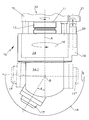
- the only figure shows an exchangeable tool unit 10, which is only indicated on a spindle 11 in the drawing Machine tool 12 is attached.
- the tool unit 10 has an inner carrier part 14, which with a C-axis drive 15 of the machine tool 12 connected and through it around the axis A of the machine spindle 11 is rotatable, which is indicated by the arrow 16.
- in the lower area 14.1 of the carrier part 14 is a tool holder 17 about a pivot axis B perpendicular to the spindle axis A arranged pivotally, two more in the drawing possible pivot positions 17 'and 17' 'of the tool holder are drawn with dashed lines. From the drawing it becomes clear that the indicated swivel range 18 of the tool holder 17 is more than 180 °.
- the upper one Area of the carrier part 14 of the assembly 10 from an adjustment part 19 in the form of an outer ring surrounded by means a fixing bolt 20 with one on the machine tool 12 arranged block 21 or connectable to the carrier part 14 is. If the support part 14 is rotated and is the adjustment part 19 fixed by the fixing bolt on the block 21, so the relative movement between the carrier part 14 and the adjusting part 19 via a gear not shown here transferred to the tool holder 17 and thereby the Angle a with respect to spindle axis A changed. Subsequently the adjustment part 19 is coupled again to the support part 14, so that the tool holder 17 with the set Angle a pivoted about axis A for workpiece machining can be.
- the block 21 can be ring-shaped and designed to be rotatable or on a ring track around the C-axis drive 15 to be movable.
Landscapes
- Engineering & Computer Science (AREA)
- Mechanical Engineering (AREA)
- Machine Tool Units (AREA)
- Stored Programmes (AREA)
- Ultra Sonic Daignosis Equipment (AREA)
- Brushes (AREA)
- Turning (AREA)
- Jigs For Machine Tools (AREA)
Applications Claiming Priority (2)
| Application Number | Priority Date | Filing Date | Title |
|---|---|---|---|
| DE10158898A DE10158898C1 (de) | 2001-11-30 | 2001-11-30 | Einwechselbares Werkzeug-Aggregat |
| DE10158898 | 2001-11-30 |
Publications (3)
| Publication Number | Publication Date |
|---|---|
| EP1316385A2 true EP1316385A2 (fr) | 2003-06-04 |
| EP1316385A3 EP1316385A3 (fr) | 2005-06-22 |
| EP1316385B1 EP1316385B1 (fr) | 2006-11-22 |
Family
ID=7707602
Family Applications (1)
| Application Number | Title | Priority Date | Filing Date |
|---|---|---|---|
| EP02023182A Expired - Lifetime EP1316385B1 (fr) | 2001-11-30 | 2002-10-16 | Tête d'outil interchangeable |
Country Status (3)
| Country | Link |
|---|---|
| EP (1) | EP1316385B1 (fr) |
| AT (1) | ATE345896T1 (fr) |
| DE (2) | DE10158898C1 (fr) |
Cited By (11)
| Publication number | Priority date | Publication date | Assignee | Title |
|---|---|---|---|---|
| WO2006069637A1 (fr) * | 2004-12-23 | 2006-07-06 | Benz Gmbh Werkzeug- Und Maschinenbau Kg | Ensemble d'outils reglable |
| WO2006084617A1 (fr) * | 2005-02-10 | 2006-08-17 | Benz Gmbh Werkzeug- Und Maschinenbau Kg | Dispositif porte-outils a entrainement |
| EP1741512A1 (fr) * | 2005-07-04 | 2007-01-10 | REICH SPEZIALMASCHINEN GmbH | Tête d'outil réglable |
| EP2135706A1 (fr) * | 2008-06-19 | 2009-12-23 | HSD S.p.A. | Tête d'usinage |
| US7891920B2 (en) * | 2006-12-27 | 2011-02-22 | Nsk Ltd. | Spindle device and machining center including the same |
| DE102010005569A1 (de) * | 2010-01-22 | 2011-07-28 | Benz GmbH Werkzeugsysteme, 77716 | Doppelschwenkwechseladapter |
| CN102303265A (zh) * | 2011-08-15 | 2012-01-04 | 四川欧曼机械有限公司 | 角度可调整的主轴装置 |
| WO2013167763A1 (fr) * | 2012-05-11 | 2013-11-14 | Fundacion Tekniker | Dispositif de coupe |
| WO2016020796A1 (fr) * | 2014-08-08 | 2016-02-11 | M.T. S.R.L. | Module de décolletage électrique |
| EP2514545B1 (fr) * | 2011-03-21 | 2016-09-28 | Biesse S.p.A. | Tête de travail et méthode de travail pour des pièces de bois ou de matériaux similaires |
| CN117862925A (zh) * | 2024-02-26 | 2024-04-12 | 广东海思智能装备有限公司 | 一种斜y车铣复合型数控机床 |
Families Citing this family (3)
| Publication number | Priority date | Publication date | Assignee | Title |
|---|---|---|---|---|
| DE102007038312A1 (de) * | 2007-08-14 | 2009-02-19 | Depo Gmbh & Co. Kg | System zur Aufnahme von Bearbeitungsköpfen an einem Bearbeitungszentrum |
| DE102007041809B4 (de) * | 2007-08-30 | 2017-01-12 | Rolls-Royce Deutschland Ltd & Co Kg | Werkzeughalter für automatischen Werkzeugwechsel |
| CN113245905B (zh) * | 2021-05-13 | 2022-05-17 | 哈尔滨工业大学 | 一种可调整金刚石刀具前角与高度的方法 |
Family Cites Families (4)
| Publication number | Priority date | Publication date | Assignee | Title |
|---|---|---|---|---|
| DE1552393B1 (de) * | 1966-10-31 | 1969-10-16 | Froriep Gmbh Maschf | Schwerwerkzeugmaschine |
| USRE32415E (en) * | 1980-03-17 | 1987-05-12 | Adjustable power transmitting device | |
| DE19718396C2 (de) * | 1997-04-30 | 2001-10-31 | Homag Maschinenbau Ag | Erweiterungsaggregat für ein Bearbeitungszentrum |
| DE19957659A1 (de) * | 1999-11-30 | 2001-06-07 | Hiltner Sonderteilebau | Werkzeugmaschine mit verschwenkbaren Spindelstock für eine Hilfsspindel |
-
2001
- 2001-11-30 DE DE10158898A patent/DE10158898C1/de not_active Expired - Lifetime
-
2002
- 2002-10-16 DE DE50208764T patent/DE50208764D1/de not_active Expired - Fee Related
- 2002-10-16 EP EP02023182A patent/EP1316385B1/fr not_active Expired - Lifetime
- 2002-10-16 AT AT02023182T patent/ATE345896T1/de active
Cited By (14)
| Publication number | Priority date | Publication date | Assignee | Title |
|---|---|---|---|---|
| WO2006069637A1 (fr) * | 2004-12-23 | 2006-07-06 | Benz Gmbh Werkzeug- Und Maschinenbau Kg | Ensemble d'outils reglable |
| WO2006084617A1 (fr) * | 2005-02-10 | 2006-08-17 | Benz Gmbh Werkzeug- Und Maschinenbau Kg | Dispositif porte-outils a entrainement |
| EP1741512A1 (fr) * | 2005-07-04 | 2007-01-10 | REICH SPEZIALMASCHINEN GmbH | Tête d'outil réglable |
| US7891920B2 (en) * | 2006-12-27 | 2011-02-22 | Nsk Ltd. | Spindle device and machining center including the same |
| CN101623880B (zh) * | 2008-06-19 | 2013-09-25 | Hsd公司 | 操作头 |
| CN101623880A (zh) * | 2008-06-19 | 2010-01-13 | Hsd公司 | 操作头 |
| US8414232B2 (en) | 2008-06-19 | 2013-04-09 | Hsd S.P.A. | Operating head |
| EP2135706A1 (fr) * | 2008-06-19 | 2009-12-23 | HSD S.p.A. | Tête d'usinage |
| DE102010005569A1 (de) * | 2010-01-22 | 2011-07-28 | Benz GmbH Werkzeugsysteme, 77716 | Doppelschwenkwechseladapter |
| EP2514545B1 (fr) * | 2011-03-21 | 2016-09-28 | Biesse S.p.A. | Tête de travail et méthode de travail pour des pièces de bois ou de matériaux similaires |
| CN102303265A (zh) * | 2011-08-15 | 2012-01-04 | 四川欧曼机械有限公司 | 角度可调整的主轴装置 |
| WO2013167763A1 (fr) * | 2012-05-11 | 2013-11-14 | Fundacion Tekniker | Dispositif de coupe |
| WO2016020796A1 (fr) * | 2014-08-08 | 2016-02-11 | M.T. S.R.L. | Module de décolletage électrique |
| CN117862925A (zh) * | 2024-02-26 | 2024-04-12 | 广东海思智能装备有限公司 | 一种斜y车铣复合型数控机床 |
Also Published As
| Publication number | Publication date |
|---|---|
| DE10158898C1 (de) | 2003-06-26 |
| ATE345896T1 (de) | 2006-12-15 |
| EP1316385B1 (fr) | 2006-11-22 |
| DE50208764D1 (de) | 2007-01-04 |
| EP1316385A3 (fr) | 2005-06-22 |
Similar Documents
| Publication | Publication Date | Title |
|---|---|---|
| EP1316385B1 (fr) | Tête d'outil interchangeable | |
| EP0664176B1 (fr) | Fraiseuse-aléseuse universelle | |
| EP1415758B1 (fr) | Unité d'usinage pour machines à fraiser et à aléser programmable | |
| DD226242A5 (de) | Getriebekopf fuer manipulatoren | |
| DE4214266A1 (de) | Vorrichtung zur fuehrung eines werkstuecks oder werkzeugs bei der bearbeitung torischer oder sphaerischer flaechen optischer linsen auf schleif- oder poliermaschinen | |
| WO2010145752A1 (fr) | Dispositif de réglage du carrossage et/ou du parallélisme des roues d'une suspension | |
| DE112016003597T5 (de) | Brenner-Winkeleinstelleinrichtung und diese verwendende Schneidevorrichtung | |
| DE102010041466B4 (de) | Vorrichtung zum Positionieren eines Werkstücks | |
| EP2295200A1 (fr) | Tête d'outil pour l'utilisation dans une machine à plusieurs axes, machine à plusieurs axes dotée d'une telle tête d'outil et utilisation d'une telle machine | |
| DE2937976A1 (de) | Maschine zum erzeugen von konvexen und/oder konkaven sphaerischen flaechen, insbesondere solcher von optischen linsen | |
| DE3701446C2 (de) | Innenrundschleifmaschine | |
| WO2006069637A1 (fr) | Ensemble d'outils reglable | |
| DE19627457A1 (de) | Einrichtung zum spielfreien Antreiben eines Drehtisches o. dgl. um eine Drehachse, insbesondere für eine Verzahnmaschine | |
| DE69817570T2 (de) | Drehantrieb für einem arm, wie einen roboterarm, um eine vertikalachse und handhabungsroboter mit einem derartigen antrieb | |
| DE2225476B2 (de) | Betätigungsvorrichtung | |
| DE3513056A1 (de) | Gelenk-antriebsanordnung | |
| DE102005032487C5 (de) | Werkzeugaggregat | |
| EP4029637A1 (fr) | Tête de fraisage à haute précision, fraiseuse dotée d'une tête de fraisage et procédé de positionnement d'une tête de fraisage à haute précision | |
| DE60303285T2 (de) | Antropomorpher Werkzeugmaschinenkopf mit einer Arbeitseinheit von reduzierten radialen Abmessungen | |
| WO1989007038A1 (fr) | Mecanisme articule pour outillage | |
| DE102017122067A1 (de) | Roboterfräsen | |
| DE102011119890B4 (de) | 1Werkzeug, insbesondere Schraubwerkzeugmit schwenkbarem Winkelkopf | |
| DE4131858A1 (de) | Verstellvorrichtung fuer schneekanonen | |
| DE102006026193B3 (de) | Winkelaggregat | |
| DE19904577A1 (de) | Teileinrichtung |
Legal Events
| Date | Code | Title | Description |
|---|---|---|---|
| PUAI | Public reference made under article 153(3) epc to a published international application that has entered the european phase |
Free format text: ORIGINAL CODE: 0009012 |
|
| AK | Designated contracting states |
Designated state(s): AT BE BG CH CY CZ DE DK EE ES FI FR GB GR IE IT LI LU MC NL PT SE SK TR |
|
| AX | Request for extension of the european patent |
Extension state: AL LT LV MK RO SI |
|
| PUAL | Search report despatched |
Free format text: ORIGINAL CODE: 0009013 |
|
| AK | Designated contracting states |
Kind code of ref document: A3 Designated state(s): AT BE BG CH CY CZ DE DK EE ES FI FR GB GR IE IT LI LU MC NL PT SE SK TR |
|
| AX | Request for extension of the european patent |
Extension state: AL LT LV MK RO SI |
|
| RIC1 | Information provided on ipc code assigned before grant |
Ipc: 7B 23Q 5/04 A Ipc: 7B 23Q 1/54 B |
|
| 17P | Request for examination filed |
Effective date: 20050715 |
|
| AKX | Designation fees paid |
Designated state(s): AT BE BG CH CY CZ DE DK EE ES FI FR GB GR IE IT LI LU MC NL PT SE SK TR |
|
| GRAP | Despatch of communication of intention to grant a patent |
Free format text: ORIGINAL CODE: EPIDOSNIGR1 |
|
| GRAS | Grant fee paid |
Free format text: ORIGINAL CODE: EPIDOSNIGR3 |
|
| GRAA | (expected) grant |
Free format text: ORIGINAL CODE: 0009210 |
|
| AK | Designated contracting states |
Kind code of ref document: B1 Designated state(s): AT BE BG CH CY CZ DE DK EE ES FI FR GB GR IE IT LI LU MC NL PT SE SK TR |
|
| PG25 | Lapsed in a contracting state [announced via postgrant information from national office to epo] |
Ref country code: SK Free format text: LAPSE BECAUSE OF FAILURE TO SUBMIT A TRANSLATION OF THE DESCRIPTION OR TO PAY THE FEE WITHIN THE PRESCRIBED TIME-LIMIT Effective date: 20061122 Ref country code: NL Free format text: LAPSE BECAUSE OF FAILURE TO SUBMIT A TRANSLATION OF THE DESCRIPTION OR TO PAY THE FEE WITHIN THE PRESCRIBED TIME-LIMIT Effective date: 20061122 Ref country code: FI Free format text: LAPSE BECAUSE OF FAILURE TO SUBMIT A TRANSLATION OF THE DESCRIPTION OR TO PAY THE FEE WITHIN THE PRESCRIBED TIME-LIMIT Effective date: 20061122 Ref country code: CZ Free format text: LAPSE BECAUSE OF FAILURE TO SUBMIT A TRANSLATION OF THE DESCRIPTION OR TO PAY THE FEE WITHIN THE PRESCRIBED TIME-LIMIT Effective date: 20061122 Ref country code: IE Free format text: LAPSE BECAUSE OF FAILURE TO SUBMIT A TRANSLATION OF THE DESCRIPTION OR TO PAY THE FEE WITHIN THE PRESCRIBED TIME-LIMIT Effective date: 20061122 |
|
| REG | Reference to a national code |
Ref country code: GB Ref legal event code: FG4D Free format text: NOT ENGLISH |
|
| REG | Reference to a national code |
Ref country code: CH Ref legal event code: EP |
|
| REG | Reference to a national code |
Ref country code: IE Ref legal event code: FG4D Free format text: LANGUAGE OF EP DOCUMENT: GERMAN |
|
| REF | Corresponds to: |
Ref document number: 50208764 Country of ref document: DE Date of ref document: 20070104 Kind code of ref document: P |
|
| REG | Reference to a national code |
Ref country code: CH Ref legal event code: NV Representative=s name: ROTTMANN, ZIMMERMANN + PARTNER AG |
|
| GBT | Gb: translation of ep patent filed (gb section 77(6)(a)/1977) |
Effective date: 20070125 |
|
| PG25 | Lapsed in a contracting state [announced via postgrant information from national office to epo] |
Ref country code: DK Free format text: LAPSE BECAUSE OF FAILURE TO SUBMIT A TRANSLATION OF THE DESCRIPTION OR TO PAY THE FEE WITHIN THE PRESCRIBED TIME-LIMIT Effective date: 20070222 Ref country code: BG Free format text: LAPSE BECAUSE OF FAILURE TO SUBMIT A TRANSLATION OF THE DESCRIPTION OR TO PAY THE FEE WITHIN THE PRESCRIBED TIME-LIMIT Effective date: 20070222 Ref country code: SE Free format text: LAPSE BECAUSE OF FAILURE TO SUBMIT A TRANSLATION OF THE DESCRIPTION OR TO PAY THE FEE WITHIN THE PRESCRIBED TIME-LIMIT Effective date: 20070222 |
|
| PG25 | Lapsed in a contracting state [announced via postgrant information from national office to epo] |
Ref country code: ES Free format text: LAPSE BECAUSE OF FAILURE TO SUBMIT A TRANSLATION OF THE DESCRIPTION OR TO PAY THE FEE WITHIN THE PRESCRIBED TIME-LIMIT Effective date: 20070305 |
|
| PG25 | Lapsed in a contracting state [announced via postgrant information from national office to epo] |
Ref country code: PT Free format text: LAPSE BECAUSE OF FAILURE TO SUBMIT A TRANSLATION OF THE DESCRIPTION OR TO PAY THE FEE WITHIN THE PRESCRIBED TIME-LIMIT Effective date: 20070423 |
|
| NLV1 | Nl: lapsed or annulled due to failure to fulfill the requirements of art. 29p and 29m of the patents act | ||
| ET | Fr: translation filed | ||
| REG | Reference to a national code |
Ref country code: IE Ref legal event code: FD4D |
|
| PLBE | No opposition filed within time limit |
Free format text: ORIGINAL CODE: 0009261 |
|
| STAA | Information on the status of an ep patent application or granted ep patent |
Free format text: STATUS: NO OPPOSITION FILED WITHIN TIME LIMIT |
|
| 26N | No opposition filed |
Effective date: 20070823 |
|
| BERE | Be: lapsed |
Owner name: WEINMANN HOLZBAUSYSTEMTECHNIK G.M.B.H. Effective date: 20071031 |
|
| PG25 | Lapsed in a contracting state [announced via postgrant information from national office to epo] |
Ref country code: GR Free format text: LAPSE BECAUSE OF FAILURE TO SUBMIT A TRANSLATION OF THE DESCRIPTION OR TO PAY THE FEE WITHIN THE PRESCRIBED TIME-LIMIT Effective date: 20070223 |
|
| PG25 | Lapsed in a contracting state [announced via postgrant information from national office to epo] |
Ref country code: MC Free format text: LAPSE BECAUSE OF NON-PAYMENT OF DUE FEES Effective date: 20071031 |
|
| PG25 | Lapsed in a contracting state [announced via postgrant information from national office to epo] |
Ref country code: DE Free format text: LAPSE BECAUSE OF NON-PAYMENT OF DUE FEES Effective date: 20080501 |
|
| PG25 | Lapsed in a contracting state [announced via postgrant information from national office to epo] |
Ref country code: BE Free format text: LAPSE BECAUSE OF NON-PAYMENT OF DUE FEES Effective date: 20071031 |
|
| PG25 | Lapsed in a contracting state [announced via postgrant information from national office to epo] |
Ref country code: EE Free format text: LAPSE BECAUSE OF FAILURE TO SUBMIT A TRANSLATION OF THE DESCRIPTION OR TO PAY THE FEE WITHIN THE PRESCRIBED TIME-LIMIT Effective date: 20061122 |
|
| PG25 | Lapsed in a contracting state [announced via postgrant information from national office to epo] |
Ref country code: LU Free format text: LAPSE BECAUSE OF NON-PAYMENT OF DUE FEES Effective date: 20071016 Ref country code: CY Free format text: LAPSE BECAUSE OF FAILURE TO SUBMIT A TRANSLATION OF THE DESCRIPTION OR TO PAY THE FEE WITHIN THE PRESCRIBED TIME-LIMIT Effective date: 20061122 |
|
| PG25 | Lapsed in a contracting state [announced via postgrant information from national office to epo] |
Ref country code: TR Free format text: LAPSE BECAUSE OF FAILURE TO SUBMIT A TRANSLATION OF THE DESCRIPTION OR TO PAY THE FEE WITHIN THE PRESCRIBED TIME-LIMIT Effective date: 20061122 |
|
| PGFP | Annual fee paid to national office [announced via postgrant information from national office to epo] |
Ref country code: AT Payment date: 20101029 Year of fee payment: 9 Ref country code: FR Payment date: 20101104 Year of fee payment: 9 |
|
| PGFP | Annual fee paid to national office [announced via postgrant information from national office to epo] |
Ref country code: CH Payment date: 20101001 Year of fee payment: 9 |
|
| PGFP | Annual fee paid to national office [announced via postgrant information from national office to epo] |
Ref country code: GB Payment date: 20101020 Year of fee payment: 9 |
|
| PGFP | Annual fee paid to national office [announced via postgrant information from national office to epo] |
Ref country code: IT Payment date: 20101022 Year of fee payment: 9 |
|
| REG | Reference to a national code |
Ref country code: CH Ref legal event code: PFA Owner name: WEINMANN HOLZBAUSYSTEMTECHNIK GMBH Free format text: WEINMANN HOLZBAUSYSTEMTECHNIK GMBH#FORCHENSTRASSE 50#72813 ST. JOHANN (DE) -TRANSFER TO- WEINMANN HOLZBAUSYSTEMTECHNIK GMBH#FORCHENSTRASSE 50#72813 ST. JOHANN (DE) |
|
| REG | Reference to a national code |
Ref country code: CH Ref legal event code: PL |
|
| GBPC | Gb: european patent ceased through non-payment of renewal fee |
Effective date: 20111016 |
|
| REG | Reference to a national code |
Ref country code: FR Ref legal event code: ST Effective date: 20120629 |
|
| PG25 | Lapsed in a contracting state [announced via postgrant information from national office to epo] |
Ref country code: CH Free format text: LAPSE BECAUSE OF NON-PAYMENT OF DUE FEES Effective date: 20111031 Ref country code: LI Free format text: LAPSE BECAUSE OF NON-PAYMENT OF DUE FEES Effective date: 20111031 |
|
| PG25 | Lapsed in a contracting state [announced via postgrant information from national office to epo] |
Ref country code: IT Free format text: LAPSE BECAUSE OF NON-PAYMENT OF DUE FEES Effective date: 20111016 Ref country code: FR Free format text: LAPSE BECAUSE OF NON-PAYMENT OF DUE FEES Effective date: 20111102 Ref country code: GB Free format text: LAPSE BECAUSE OF NON-PAYMENT OF DUE FEES Effective date: 20111016 |
|
| REG | Reference to a national code |
Ref country code: AT Ref legal event code: MM01 Ref document number: 345896 Country of ref document: AT Kind code of ref document: T Effective date: 20111016 |
|
| PG25 | Lapsed in a contracting state [announced via postgrant information from national office to epo] |
Ref country code: AT Free format text: LAPSE BECAUSE OF NON-PAYMENT OF DUE FEES Effective date: 20111016 |