EP1316475A2 - Construction d'un levier de commutation pour véhicule - Google Patents
Construction d'un levier de commutation pour véhicule Download PDFInfo
- Publication number
- EP1316475A2 EP1316475A2 EP02025963A EP02025963A EP1316475A2 EP 1316475 A2 EP1316475 A2 EP 1316475A2 EP 02025963 A EP02025963 A EP 02025963A EP 02025963 A EP02025963 A EP 02025963A EP 1316475 A2 EP1316475 A2 EP 1316475A2
- Authority
- EP
- European Patent Office
- Prior art keywords
- lever
- detent
- control rod
- rotary knob
- control
- Prior art date
- Legal status (The legal status is an assumption and is not a legal conclusion. Google has not performed a legal analysis and makes no representation as to the accuracy of the status listed.)
- Withdrawn
Links
- 238000010276 construction Methods 0.000 title claims description 15
- 230000007246 mechanism Effects 0.000 claims abstract description 30
- 238000003780 insertion Methods 0.000 claims description 6
- 230000037431 insertion Effects 0.000 claims description 6
- 230000007257 malfunction Effects 0.000 abstract description 7
- 230000002265 prevention Effects 0.000 abstract 1
- 230000000694 effects Effects 0.000 description 4
- 210000000078 claw Anatomy 0.000 description 3
- 230000007935 neutral effect Effects 0.000 description 3
- 238000005299 abrasion Methods 0.000 description 2
- 238000000465 moulding Methods 0.000 description 2
- 241000206607 Porphyra umbilicalis Species 0.000 description 1
- 229910000831 Steel Inorganic materials 0.000 description 1
- 238000006073 displacement reaction Methods 0.000 description 1
- 239000003550 marker Substances 0.000 description 1
- 239000000463 material Substances 0.000 description 1
- 230000002093 peripheral effect Effects 0.000 description 1
- 239000000843 powder Substances 0.000 description 1
- 239000011347 resin Substances 0.000 description 1
- 229920005989 resin Polymers 0.000 description 1
- 239000010959 steel Substances 0.000 description 1
- 230000008719 thickening Effects 0.000 description 1
Images


Classifications
-
- B—PERFORMING OPERATIONS; TRANSPORTING
- B60—VEHICLES IN GENERAL
- B60Q—ARRANGEMENT OF SIGNALLING OR LIGHTING DEVICES, THE MOUNTING OR SUPPORTING THEREOF OR CIRCUITS THEREFOR, FOR VEHICLES IN GENERAL
- B60Q1/00—Arrangement of optical signalling or lighting devices, the mounting or supporting thereof or circuits therefor
- B60Q1/02—Arrangement of optical signalling or lighting devices, the mounting or supporting thereof or circuits therefor the devices being primarily intended to illuminate the way ahead or to illuminate other areas of way or environments
- B60Q1/04—Arrangement of optical signalling or lighting devices, the mounting or supporting thereof or circuits therefor the devices being primarily intended to illuminate the way ahead or to illuminate other areas of way or environments the devices being headlights
- B60Q1/14—Arrangement of optical signalling or lighting devices, the mounting or supporting thereof or circuits therefor the devices being primarily intended to illuminate the way ahead or to illuminate other areas of way or environments the devices being headlights having dimming means
- B60Q1/1446—Arrangement of optical signalling or lighting devices, the mounting or supporting thereof or circuits therefor the devices being primarily intended to illuminate the way ahead or to illuminate other areas of way or environments the devices being headlights having dimming means controlled by mechanically actuated switches
- B60Q1/1453—Hand actuated switches
- B60Q1/1461—Multifunction switches for dimming headlights and controlling additional devices, e.g. for controlling direction indicating lights
- B60Q1/1469—Multifunction switches for dimming headlights and controlling additional devices, e.g. for controlling direction indicating lights controlled by or attached to a single lever, e.g. steering column stalk switches
- B60Q1/1476—Multifunction switches for dimming headlights and controlling additional devices, e.g. for controlling direction indicating lights controlled by or attached to a single lever, e.g. steering column stalk switches comprising switch controlling means located near the free end of the lever, e.g. press buttons, rotatable rings
Definitions
- the present invention relates to a construction of an on-vehicle lever switch for providing operational instructions, for example, for turning a headlamp of a vehicle ON and OFF.
- an on-vehicle lever switch in the related art, there is the one disclosed for example in JP-A-10-12100.
- the construction of the on-vehicle lever switch includes a control lever attached on a steering column for providing electrical operational instructions, for example, for turning the headlamp of the vehicle ON and OFF, and the control lever includes control knobs as rotary knobs disposed on the distal side thereof with a knob middle as a fixed knob interposed therebetween.
- the aforementioned knob middle is formed with detent troughs on both axial end surfaces thereof, and a detent ball supported on each control knob is in resilient contact with each detent trough by an urging force of a detent spring.
- a projection formed on the control knob engages a hole on the knob middle to construct a stopper to limit the rotary movement of the control knob.
- Lighting operation such as turning the headlamp ON and OFF is performed by operating such control knobs.
- the detent ball on each control knob is brought into resilient contact with the detent trough on the knob middle to provide detention to the control knob.
- the limit of rotary movement of the control knob may be determined by abutment of the projection on the control knob against the end of the hole on the knob middle in the rotational direction.
- the other control knob that is not operated may slightly rotate in conjunction with the rotation of the operated control knob.
- the projection thereof abuts against the end of the hole on the knob middle, and thus the fixed knob middle is displaced in the direction of rotation due to axial deflection of resin.
- a rotational force is transmitted via the detent ball in resilient contact with the detent trough of the knob middle and the detent spring to the other control knob that is not operated, and thus the control knob that is not operated may rotate together in the direction of rotation.
- a first aspect of the invention is a lever switch including a first rotary knob and a second rotary knob disposed on the distal side of a control lever and being capable of providing predetermined electrical operational instructions by rotating the first rotary knob and the second rotary knob about the axis respectively, wherein a first detent mechanism is provided for providing detention against rotational operation of one of the first and second rotary knobs on the distal side of the control lever, a lever guide formed with a lever guide hole is provided on the control lever, a lever shaft extending from the distal side to the proximal side of the control lever is disposed in the lever guide hole, the other one of the first and second rotary knobs is connected to the distal side of the lever shaft, a control rod is provided for providing the electrical operational instructions on the proximal side of the lever shaft, and a second detent mechanism for providing detention against the rotational operation of the other one of the first and second rotary knobs is provided between the proximal side of the lever guide and the control rod.
- a second aspect of the invention is a construction of an on-vehicle lever switch as set forth in the first aspect of the invention, wherein the second detent mechanism includes a detent body and a detent spring supported on the control lever and a detent groove formed on the control rod, the control rod includes an engaging section for enabling the electrical operational instructions and a notched section for enabling insertion of the lever shaft along the axial center of the lever guide hole in addition to the detent groove, and a locking section with which the notched side of the control rod engages by an urging force of the detent spring exerted by rotating the control rod in one direction about the axis is provided on the proximal side of the lever guide.
- a third aspect of the invention is a construction of an on-vehicle lever switch as set forth in the first aspect or the second aspect of the invention, wherein a stopper for determining the limit of rotation of the control rod by allowing the notched side of the control rod to be abutted when the control rod is rotated is provided on the proximal side of the lever guide.
- a fourth aspect of the invention is a construction of an on-vehicle lever switch as stated any one of the second aspect and the third aspect of the invention, wherein a mounting space being in communication with the lever guide hole for arranging the control rod is provided on the proximal side of the lever guide, and a locking hole with which the notched side of the control rod engages to form the locking section and having the stopper is formed on one side of the mounting space intersecting the axial center of the lever guide hole.
- a fifth aspect of the invention is a construction of on-vehicle lever switch as set forth in any one of the first aspect to the fourth aspect of the invention, wherein the first rotary knob and the second rotary knob are disposed on the distal side of the control lever with the immovable fixed body interposed therebetween, and the first detent mechanism includes the detent body and the detent spring provided on one of the first and second rotary knobs or on the fixed body, and the detent groove formed on the other one of the first and second rotary knobs with which the detent body is brought into resilient contact by an urging force of the detent spring.
- the first rotary knob and the second rotary knob are disposed on the distal side of the control lever, and prescribed electrical operational instructions, for example, for turning the headlamp ON and OFF, and turning the fog lamp ON and OFF may be provided by rotating the first rotary knob and the second rotary knob about the axis.
- electrical operational instructions for example, for turning the headlamp ON and OFF, and turning the fog lamp ON and OFF
- rotating the first rotary knob and the second rotary knob about the axis When rotating one of the first and second rotary knobs, detention against the rotational operation may be provided by the first detent mechanism.
- the control rod on the distal side is operated via the lever shaft extending in the lever guide hole from the distal side to the proximal side of the control lever, and a movable element provided with a movable contact point is moved in conjunction therewith, so that the electrical operational instructions, for example, for turning the headlamp ON and OFF may be provided.
- detention may be provided by the second detent mechanism provided between the proximal side of the lever guide and the control rod.
- the first detent mechanism for providing detention against the rotational operation of one of the first and second rotary knobs is provided on the distal side of the control lever, and the second detent mechanism for providing detention against the rotational operation of the other one of those is provided on the proximal side of the control lever, the first and second detent mechanisms may be prevented from working with each other in the direction of rotation, and thus coupled rotation such that rotation of one of the first and second rotary knobs to the limit causes rotation of the other one of those may be prevented. Therefore, malfunction of one of the first and second rotary knobs caused by the operation of the other one of those may be prevented while downsizing the entire control lever without increasing rigidity of the entire control lever.
- the second detent mechanism in addition to the effect of the invention as set forth in the first aspect of the invention, includes the detent body and the detent spring supported on the control lever, and the detent groove formed on the control rod, and is able to provide detention against the rotational operation reliably by resilient contact of the detent body urged by the detent spring with the detent groove on the control rod on the occasion of rotating the other one of the first and second rotary knobs.
- control rod also includes the engaging section that enables the electrical operational instructions, and the notched section that enables insertion of the lever shaft along the axial center of the lever guide hole in addition to the detent groove, the lever shaft can easily be inserted and assembled along the axial center of the lever guide hole on the occasion of assembly.
- the notched side of the control rod may be engaged with the locking section provided on the proximal side of the control lever by an urging force of the detent spring. Therefore, in this state of engagement, the lever shaft and the control rod do not project and drop out from the lever guide hole due to an urging force of the detent spring even when the operator unlinks hands, and thus assembly may be performed quite easily.
- the rotation in addition to the effect of the invention as set forth in the first or second aspect of the invention, when the other one of the first and second rotary knobs is rotated, the rotation can be constrained by abutment of the notched side of the control rod to the stopper provided on the proximal side of the lever guide at the limit of rotation, and thus the rotational operation of the other one of the first and second rotary knobs may be reliably performed.
- first and second detent mechanisms do not work together in the direction of rotation, even when the other one of the first and second rotary knobs rotates and displaces over the limit due to the axial deflection caused by abutment of the notched side of the control rod to the stopper, one of the first and second rotary knobs does not rotate together, and thus malfunction can reliably be prevented.
- the control rod since the mounting space in communication with the lever guide hole is provided on the proximal side of the lever guide, the control rod may be disposed in the mounting space. Since the locking hole is formed on one side of the mounting space intersecting the axial center of the lever guide hole, the notched side of the control rod may be engaged with the locking hole via an urging force of the detent spring of the second detent mechanism by rotating the control rod in one direction about the axis, thereby reliably preventing dropping out of the lever shaft and the control rod when assembling.
- the aforementioned locking hole is provided with the stopper, when the control rod is rotated to the limit, the notched side of the control rod can reliably be abutted to the stopper, and thus the other one of the first and second rotary knobs may reliably be positioned at the limit of rotation, thereby enabling precise operation.
- the first rotary knob and second rotary knob are disposed on the distal side of the control lever with the immovably mounted fixed knob interposed therebetween and thus the detent body provided on one of the first and second rotary knobs or on the fixed knob is brought into resilient contact with the detent groove formed on the other one of those by an urging force of the detent spring when rotating one of the first and second rotary knobs, detention against the rotational operation of the first and second rotary knobs may reliably be provided.
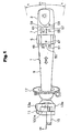
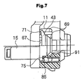
- Fig. 1 to Fig. 6 relate to an embodiment of the present invention, in which Fig. 1 is a front view of a control lever of a lever switch, Fig. 2 is a cross sectional view taken along the line SA-SA in Fig. 1, Fig. 3 is a cross sectional view of a principal portion of a first detent mechanism, Fig. 4 is an enlarged cross sectional view showing a distal side of the control lever, Fig. 5 is an enlarged front view showing the distal side of the control lever with a movable element, Fig. 6 is an enlarged cross sectional view of the distal side of the control lever when viewed in the directions indicated by the arrows SB-SB in Fig. 4, and Fig. 7 is a partially exploded enlarged plan view showing the distal side of the control lever.
- a structure of an on-vehicle lever switch relates to an on-vehicle combination switch as a lever switch, which is mounted on the steering column via a case, not shown, to be mounted on the proximal side of a control lever 1 and a body to be mounted on the steering column, for example, on the right side of a right hand drive car.
- the body includes a cylindrical pipe for inserting the steering shaft at the center thereof, so that the case is inserted therethrough from the right side and attached on the right side, and is secured on the steering column with a screw.
- the control lever 1 is used for providing a predetermined electrical operational instructions, and includes, for example, a turn signal switch, a lighting switch for turning the head light ON and OFF, a main-dimmer changeover switch, a passing switch, a fog lamp switch for turning a fog lamp ON and OFF.
- the control lever 1 includes a lever shaft 39, a first rotary knob 3 provided at the distal end of the lever shaft 39, a lever guide 19 for rotatably supporting the lever shaft 39, a lever portion 9 and a fixed knob 7 fitted on the lever guide 19, and a second rotary knob 5 rotatably fitted on the lever guide 19, and is capable of pivoting from front to back and side to side.
- the control lever 1 of the combination switch includes the first rotary knob 3 and the second rotary knob 5 on the distal side thereof so as to be capable of rotating about the axis.
- the first rotary knob 3 and the second rotary knob 5 are disposed with a fixed knob 7 on the fixed side that is not capable of rotating about the axis interposed therebetween as shown in Fig. 2.
- the control lever 1 is provided with the lever portion 9 on the fixed side that is not capable of rotating about the axis adjacent to the second rotary knob 5, and the lever portion 19 rotatably supporting the second rotary knob 5 is fixed in the lever portion 9 by means of a resilient locking strip 19a.
- the fixed knob 7 must simply be a fixed body that does not rotate with respect to the first and second rotary knobs 3, 5, and thus it may be disposed so as to be hidden in the first or the second rotary knob 3, 5.
- a control rod mounting unit 11 On the outer surface of the control rod mounting unit 11, there are provided a pair of shanks 13a, 13b projected therefrom and rotatably supported by a movable plate 100 that is rotatably supported by the case.
- the control lever 1 pivots in the directions indicated by the arrows C and D about the shanks 13a, 13b, and pivots in the directions indicated by the arrows A and B about a shaft 100a of the movable plate 100.
- the control rod mounting unit 11 is further provided with a detent body supporting unit 15 projected therefrom.
- a boot 17 is mounted on the proximal side of the lever portion 9.
- the boot 17 is formed into a substantially horn shape, and is mounted on the case so that the interior of the case and the like in which the proximal side of the control lever 1 is mounted cannot be viewed from the occupant.
- the control lever 1 of the combination switch has a function of a turn signal switch for flashing the turn signal by its pivotal movement in the directions indicated by the arrows A, B about the shank 100a of the movable plate 100 as shown in Fig. 1.
- the control lever 1 has also a function of a main-dimmer changeover switch and a passing switch by its pivotal movement in the directions indicated by the arrows C, D about the shanks 13a, 13b of the lever portion 9 as shown in Fig. 4.
- the first rotary knob 3 has a function of a lighting switch for turning the headlamp and the side marker lamp ON and OFF by being rotated about the axis.
- the second rotary knob 5 has a function of a fog lamp switch for turning the fog lamp on the front side or on the rear side ON and OFF by being rotated about the axis.
- the first rotary knob 3 is provided with a triangle mark 53 that serves as a mark for rotational operation as shown in Fig. 1, and the fixed knob 7 is provided with a mark 55 indicating the position for turning the headlamp OFF, a mark 57 indicating the position for turning a parking lamp ON, a mark 59 indicating the position for turning the headlamp ON, and characters (AUTO) 61 indicating the position for allowing the headlamp to be automatically turned ON and OFF.
- the second rotary knob 5 is provided with a triangle mark 47 that serves as a mark for rotational operation, and the lever portion 9 is provided on its surface adjacent to the second rotary knob 5 with a mark 49 indicating the position for turning the front fog lamp ON, a mark 50 indicating the neutral position, and a mark 51 indicating the position for turning the rear fog lamp ON.
- the cross section of the control lever 1 is as shown in Fig. 2.
- the control lever 1 has the lever guide 19 fixed in the lever portion 9.
- the lever guide 19 extends from the distal side to the proximal side of the control lever 1.
- the lever guide 19 is formed with a lever guide hole 20 passing through the axle center thereof.
- the lever portion 9 is, as shown in Fig. 2, opened in the horn shape so that the distal end thereof almost matches the diameter of the second rotary knob 5, and is fixedly mounted by engaging the resilient locking strip 9a formed in the opening thereof along the lever guide 9 with the groove formed on the outer periphery of the lever guide 19.
- the fixed knob 7 clamps the second rotary knob 5 rotatably fitted in the lever shaft 39 with the lever portion 9 so as not to move in the axial direction by being fixedly mounted on the outer periphery of the distal side of the lever guide 19.
- the second rotary knob 5 disposed between the fixed knob 7 and the lever portion 9 is rotatably supported on the outer peripheral surface of the lever guide 19 on the distal side.
- the first detent mechanism 21 includes a detent body 27 supported by a detent body supporting unit 23 provided on the second rotary knob 5 via a detent spring 25.
- the detent spring 25 is formed of a coil spring, and the detent body 27 is formed of a steel ball.
- the detent body 27 is in resilient contact with a detent groove 29 formed on the fixed knob 7 via an urging force of the detent spring 25.
- a movable contact plate 33 is supported on the second rotary knob 5 via a contact spring 31 formed of a coil spring.
- a polar plate 35 is fixed on and supported by the laver guide 19 adjacent to the movable contact plate 33, and is fitted into the opening on the lever portion 9.
- the polar plate 35 is formed with a fixed contact by insert molding so as to be exposed on the plate surface.
- the polar plate 35 is connected with a lead 37 and is connected to the fixed contact point in a conducting state.
- the lead 37 passes between the lever portion 9 and the lever guide 19 and drawn into the proximal side of the control lever 1, and is connected to the circuit for turning the fog lamps on the front side and on the rear side ON and OFF.
- the lever shaft 39 is rotatably fitted into the lever guide hole 20 on the lever guide 19.
- the lever shaft 39 is disposed in the lever guide hole 20 so as to extend straightly from the distal side to the proximal side of the control lever 1.
- a joint member 41 is fixedly mounted on the distal side of the lever shaft 39.
- the first rotary knob 3 is fixedly mounted on the joint member 41. Therefore, it is constructed in such a manner that the lever guide 19 having the lever guide hole 20 is provided on the control lever 1 and the lever shaft 39 is disposed in the lever guide hole 20 so as to extend from the distal side to the proximal side of the control lever 1.
- a tubular projection 93 of the joint member 41 that is to be mounted in a state in which the first rotary knob 3 is fixed is fitted into a notched section 95 formed on the distal side of the fixed knob 7, so that the fixed knob 7 and the joint member 41 on the first rotary knob 3 do not engage with each other in the direction of rotation at the projection 93 and the notched section 95.
- a control rod 43 is provided on the proximal side of the lever shaft 39.
- the relation between the detent body 27 and the detent groove 29 of the first detent mechanism 21 is as shown in Fig. 3, and the detent groove 29 is formed into V-shape defined by a pair of inclined surfaces 45a, 45b. Therefore, when the second rotary knob 5 is rotated and aligned with the mark 49, the detent body 27 moves upward on the inclined surface 45a, and a part of the second rotary knob 5 abuts against the stopper on the fixed knob 7 at the midpoint thereof, thereby preventing further rotation of the second rotary knob 5.
- the detent body 27 moves downward on the inclined surface 45a by an urging force of the detent spring 25, and is automatically restored to the trough of the detent groove 29, thereby restoring the second rotary knob 5 automatically to the neutral position where the triangle mark 47 points the mark 50.
- the detent body 27 moves upward on the inclined surface 45b and a part of the second rotary knob 5 likewise abuts against the stopper on the fixed knob 7 at the midpoint thereof, thereby preventing further rotation.
- the second rotary knob 5 is released at this point, the second rotary knob 5 is automatically restored to the neutral position where the triangle mark 47 points the mark 50 in the same manner as described above.
- a detent body 16 is supported by the detent body supporting unit 15 via a detent spring 18.
- the detent body 16 is in resilient contact with the detent groove on the case.
- the control rod mounting unit 11 is provided with a mounting space 65 being in communication with the lever guide hole 20 as shown in Fig. 4 and Fig. 5.
- the control rod mounting unit 11 On one side of the mounting space 65 intersecting the axial center of the lever guide hole 20, the control rod mounting unit 11 is provided with a locking hole 67 as a locking section with which the notched side of the control rod 43 that will be described later engages by being applied with an urging force of the detent spring that will also be described later when the control rod 43 is rotated in one direction about the axis during assembling the control rod 43.
- the locking hole 67 is provided so as to be orthogonal to the axial center of the lever guide hole 20.
- the control rod mounting unit 11 is further provided in the locking hole 67 with a stopper 69 that determines the rotational limit of the control rod 43 when being is rotated.
- a stopper 69 that determines the rotational limit of the control rod 43 when being is rotated.
- it is constructed in such a manner that the stopper 69 against which the notched side of the control rod 43 that will be described later abuts when the control rod 43 is rotated is provided on the proximal side of the lever guide 19. It is also constructed in such a manner that the notched side of the control rod 43 that will be described later is fitted into one side of the mounting space 65 so as to intersect the axial center of the lever guide hole 20 to construct the locking section, and the locking hole 67 having the stopper 69 is provided.
- the control rod 43 includes an engaging section 71 in the shape of a bevel gear, a notched section 73, and a detent groove forming section 75.
- the engaging section 71 enables the provision of electrical operational instructions, and engages an engaging section 79 of a movable element 77 rotatably supported by the case.
- the movable element 77 is provided with a movable contact point 81 formed of conductive metallic leaf spring material.
- Engagement between the engaging sections 71, 79 enables operation of the control lever 1 in the directions indicated by the arrows C, D in Fig. 2 about the shanks 13a, 13b.
- the notched section 73 enables insertion of the lever shaft 39 along the axial center of the lever guide hole 20.
- the notched section 73 is formed by removing the upper portion of the control rod 43 into a substantially sector form in front view.
- the second detent mechanism 83 includes a detent body 85 and a detent spring 87 supported on the control lever 1 and a detent groove 89 formed on the control rod 43 as shown in Fig. 6 and Fig. 7.
- the detent body 85 and the detent spring 87 are supported by the detent body supporting unit 91 provided on the proximal side of the lever guide 19.
- the detent groove 89 is formed on the detent groove forming section 75 of the control rod 43.
- the boot 17, the lever guide 19, the lead 37, the polar plate 35, the second rotary knob 5, the first detent mechanism 21, the lever shaft 39, the joint member 41, and the fixed knob 7 are assembled sequentially on the lever portion 9.
- the lever shaft 39 is inserted from the side of the mounting space 65 along the axial center of the lever guide hole 20.
- the notched section 73 exists on the control rod 43, the control rod 43 is not constrained by the control rod mounting unit 11 of the lever guide 19, and thus the lever shaft 39 can be inserted along the axial center of the lever guide hole 20 without problem. Therefore, assembly of the lever shaft 39 may be performed easily.
- the detent body 85 and the detent spring 87 are assembled on the detent body supporting unit 91 in advance.
- the detent body 85 is brought into resilient contact with the detent groove 89 on the control rod 43, then the control rod 43 is placed in the mounting space 65 and rotated in one direction about the axis until it comes to the state shown in Fig. 5.
- This rotation of the control rod 43 allows the notched section 73 to be fitted into the locking hole 67 as shown in Fig. 5.
- control rod 43 When releasing the hand from the control rod 43 in this state, the control rod 43 is pushed in the axial direction by an urging force of the detent spring 87 via the detent body 85 and the lower side of the notched section 73 engages the wall surface of the locking hole 67.
- the distal end of the lever shaft 39 inserted into the lever guide hole 20 projects out from the fixed knob 7 in a state in which the lower portion of the notched section 73 of the control rod 43 engages the locking hole 67.
- the joint member 41 is fixedly put on the projected distal end of the lever shaft 39.
- the first rotary knob 3 is then fixedly put on the joint member 41 to get the state shown in Fig. 2.
- the control rod 43 When assembling the first rotary knob 3, the control rod 43 is pushed in the axial direction against the detent spring 87. After assembly, the control rod 43 is held at the position slightly away from the wall surface of the locking hole 67.
- the detent spring 18 and the detent body 16 are inserted into the detent body supporting unit 15 of the lever guide 19 so as to be rotatably supported by the movable plate 100, and the movable plate 100 is rotatably supported by the case.
- the control rod 43 rotates via the lever shaft 39. This rotation brings the detent body 85 into opposed resilient contact with the detent groove 89 of the position (PARK) corresponding to the parking lamp, and the control rod 43 is positioned.
- the rotation of the control rod 43 rotates the movable element 77 via the engaging sections 71, 79. This rotation brings the movable contact point 81 into contact with the fixed contact point on the case in a predetermined state, so that the circuit of the parking lamp is closed and thus the parking lamp is illuminated.
- the detent body 85 is brought into opposed resilient contact with the detent groove 89 corresponding to the position for turning the headlamp ON (HEAD) or the detent groove 89 corresponding to the automatic position (AUTO), and then the control rod 43 is positioned.
- the movable element 77 is likewise rotated, and the movable contact point 81 is bought into contact with the fixed contact point on the case in a prescribed state, thereby the headlamp is illuminated, or the headlamp is turned ON and OFF automatically according to the lighting environment outside the car.
- the first rotary knob 3 may be provided with detention against the rotational operation via the control rod 43, the lever shaft 39, and the joint member 41.
- the detent groove forming section 75 may be formed into a sector form elongated in the direction of rotation of the control rod 43. Even when the stroke of the rotary operation of the first rotary knob 3 is increased, the detent groove forming section 75 may be opposed to the detent body 85, whereby the detent body 85 is reliably prevented form being dropped out.
- the control rod 43 is adapted to rotate and move the movable element 77 by the engaging sections 71, 79, the gear-shaped engaging sections 71, 79 are constantly engaged even when the first rotary knob 3 is rotated to a large extent. Therefore, in comparison with the device in which arm shaped member simply engages the recess on the movable element to linearly move the movable element by the pivotal movement of the arm-shaped member, the movable element 77 can be rotated in an engaged state for a long distance in the direction of rotation of the operating rod 43, whereby the operating stroke of the first rotary knob 3 may be increased.
- the mutual distances of a plurality of fixed contact points on the case that the movable contact point 81 of the movable element 77 come into contact with may be increased, and thus a rotary switch having a number of contact positions may be provided.
- a rotary switch having a number of contact positions may be provided.
- the second rotary knob 5 does not rotate in conjunction with the excessive rotation of the first rotary knob 3, and thus malfunction of the second rotary knob 5 due to strong rotational operation of the first rotary knob 3 may be prevented.
- the second rotary knob 5 repeats turning the fog lamp on the front side or the fog lamp on the rear side ON and OFF every time the triangle mark 47 is aligned with the mark 49 or 51 by its rotational operation.
- detention by the detent groove 89 and the detent body 85 may be transmitted directly to the first rotary knob 3 via the lever shaft 39, and thus rattling of the first rotary knob 3 may be prevented.
- first rotary knob 3 is adapted to provide operational instructions for turning the headlamp ON and OFF
- second rotary knob 5 is adapted to provide operational instructions for turning the fog lamp ON and OFF in the above-described embodiment
- the functions of the first and second rotary knobs 3, 5 may be selected as desired.
- control rod 43 is provided with the engaging section 79, it is also possible to employ an arm member to engage the movable element on the case instead of the engaging section 79 to allow the linear movement of the movable element.
- the stopper 69 is adapted to limit the rotation of the first rotary knob 3 when it is strongly operated toward the OFF side, it is also possible to further provide a stopper for limiting the rotation of the first rotary knob 3 when it is strongly operated toward the AUTO side.
- the stopper 69 may also be omitted.
- the locking hole 67 with which the control rod 43 is engaged at the time of assembly is not limited to a through hole, and it may be a bottomed hole.
- the locking structure does not have to be a hole, and it may be constructed by a flexible claw or the like. When employing the flexible claw projecting into the mounting space 65, it is thrust away by the control rod 43 and thus is out of the mounting space 65 at the time of assembly. However, when the control rod 43 is disposed in the mounting space 65, the claw is resiliently restored into the mounting space 65 and thus locks the control rod 43 from being dislocated.
Landscapes
- Engineering & Computer Science (AREA)
- Mechanical Engineering (AREA)
- Switches With Compound Operations (AREA)
- Rotary Switch, Piano Key Switch, And Lever Switch (AREA)
Applications Claiming Priority (2)
| Application Number | Priority Date | Filing Date | Title |
|---|---|---|---|
| JP2001362961 | 2001-11-28 | ||
| JP2001362961A JP3837324B2 (ja) | 2001-11-28 | 2001-11-28 | 車両用レバースイッチの構造 |
Publications (2)
| Publication Number | Publication Date |
|---|---|
| EP1316475A2 true EP1316475A2 (fr) | 2003-06-04 |
| EP1316475A3 EP1316475A3 (fr) | 2006-07-05 |
Family
ID=19173378
Family Applications (1)
| Application Number | Title | Priority Date | Filing Date |
|---|---|---|---|
| EP02025963A Withdrawn EP1316475A3 (fr) | 2001-11-28 | 2002-11-21 | Construction d'un levier de commutation pour véhicule |
Country Status (3)
| Country | Link |
|---|---|
| US (1) | US6781072B2 (fr) |
| EP (1) | EP1316475A3 (fr) |
| JP (1) | JP3837324B2 (fr) |
Cited By (3)
| Publication number | Priority date | Publication date | Assignee | Title |
|---|---|---|---|---|
| EP1977929A1 (fr) * | 2007-04-05 | 2008-10-08 | Ford Global Technologies, LLC | Contrôle des faisceaux de phare de véhicule |
| CN102543509A (zh) * | 2010-10-25 | 2012-07-04 | 现代自动车株式会社 | 具有照明模块的车用多功能开关 |
| US8853946B2 (en) | 2011-12-16 | 2014-10-07 | Ford Global Technologies | Method for event-based override strategy for automatic high-beam control |
Families Citing this family (11)
| Publication number | Priority date | Publication date | Assignee | Title |
|---|---|---|---|---|
| JP2004235002A (ja) * | 2003-01-30 | 2004-08-19 | Niles Co Ltd | 車両用レバースイッチの操作レバー構造 |
| US7044042B2 (en) * | 2003-11-20 | 2006-05-16 | Carl Manufacturing Usa, Inc. | Blade cutting assembly for sheet material |
| JP2008114655A (ja) * | 2006-11-01 | 2008-05-22 | Denso Corp | 車両用照明制御装置 |
| JP2009026664A (ja) | 2007-07-20 | 2009-02-05 | Niles Co Ltd | レバー・スイッチ |
| JP2010105614A (ja) * | 2008-10-31 | 2010-05-13 | Tokai Rika Co Ltd | 車両用ライト制御装置 |
| JP5617474B2 (ja) * | 2010-09-22 | 2014-11-05 | パナソニック株式会社 | 車両用レバースイッチ |
| JP6684675B2 (ja) * | 2016-07-25 | 2020-04-22 | 大和化成工業株式会社 | 組付け型車両部品 |
| JP6869424B2 (ja) * | 2018-04-06 | 2021-05-12 | 本田技研工業株式会社 | 車両用ライトスイッチ及び車両用ライトシステム |
| JP7534068B2 (ja) * | 2018-10-16 | 2024-08-14 | トヨタ自動車株式会社 | レバースイッチ及びオートライト制御装置 |
| JP2020113523A (ja) * | 2019-01-17 | 2020-07-27 | 株式会社東海理化電機製作所 | レバースイッチ装置 |
| JP7060637B2 (ja) * | 2020-03-16 | 2022-04-26 | 本田技研工業株式会社 | 車両用ライトシステム |
Citations (1)
| Publication number | Priority date | Publication date | Assignee | Title |
|---|---|---|---|---|
| JPH1012100A (ja) | 1996-06-25 | 1998-01-16 | Tokai Rika Co Ltd | レバースイッチ |
Family Cites Families (10)
| Publication number | Priority date | Publication date | Assignee | Title |
|---|---|---|---|---|
| JPS6022525Y2 (ja) * | 1978-10-06 | 1985-07-04 | 株式会社東海理化電機製作所 | 自動車用レバ−コンビネ−シヨンスイツチ |
| FR2681468B1 (fr) * | 1991-09-17 | 1995-03-03 | Jaeger | Commutateur electrique perfectionne, notamment pour vehicules automobiles. |
| JPH07335086A (ja) * | 1994-06-06 | 1995-12-22 | Tokai Rika Co Ltd | 車両用レバースイッチ装置 |
| JP3574709B2 (ja) * | 1996-01-18 | 2004-10-06 | ナイルス株式会社 | 自動車用複合スイッチレバー装置 |
| JPH10241507A (ja) * | 1997-02-28 | 1998-09-11 | Tokai Rika Co Ltd | 車両用レバースイッチ装置 |
| JPH1125804A (ja) * | 1997-06-30 | 1999-01-29 | Niles Parts Co Ltd | 車両用レバースイッチの構造 |
| JPH1153997A (ja) * | 1997-07-31 | 1999-02-26 | Niles Parts Co Ltd | 車両用レバースイッチの構造 |
| JP3495259B2 (ja) * | 1998-07-31 | 2004-02-09 | ナイルス株式会社 | 車両用レバースイッチの構造 |
| US6518524B1 (en) * | 1998-08-06 | 2003-02-11 | Grote Industries, Inc. | Multi-function stalk switch |
| JP4318354B2 (ja) * | 1999-10-04 | 2009-08-19 | ナイルス株式会社 | レバースイッチ |
-
2001
- 2001-11-28 JP JP2001362961A patent/JP3837324B2/ja not_active Expired - Fee Related
-
2002
- 2002-11-21 EP EP02025963A patent/EP1316475A3/fr not_active Withdrawn
- 2002-11-26 US US10/303,862 patent/US6781072B2/en not_active Expired - Fee Related
Patent Citations (1)
| Publication number | Priority date | Publication date | Assignee | Title |
|---|---|---|---|---|
| JPH1012100A (ja) | 1996-06-25 | 1998-01-16 | Tokai Rika Co Ltd | レバースイッチ |
Cited By (5)
| Publication number | Priority date | Publication date | Assignee | Title |
|---|---|---|---|---|
| EP1977929A1 (fr) * | 2007-04-05 | 2008-10-08 | Ford Global Technologies, LLC | Contrôle des faisceaux de phare de véhicule |
| US7755294B2 (en) | 2007-04-05 | 2010-07-13 | Jaguar Cars Limited | Vehicle headlight beam controls |
| CN102543509A (zh) * | 2010-10-25 | 2012-07-04 | 现代自动车株式会社 | 具有照明模块的车用多功能开关 |
| CN102543509B (zh) * | 2010-10-25 | 2015-11-25 | 现代自动车株式会社 | 具有照明模块的车用多功能开关 |
| US8853946B2 (en) | 2011-12-16 | 2014-10-07 | Ford Global Technologies | Method for event-based override strategy for automatic high-beam control |
Also Published As
| Publication number | Publication date |
|---|---|
| EP1316475A3 (fr) | 2006-07-05 |
| US20030098223A1 (en) | 2003-05-29 |
| US6781072B2 (en) | 2004-08-24 |
| JP3837324B2 (ja) | 2006-10-25 |
| JP2003162945A (ja) | 2003-06-06 |
Similar Documents
| Publication | Publication Date | Title |
|---|---|---|
| US6781072B2 (en) | Construction of on-vehicle lever switch | |
| US5272290A (en) | Lever switch device | |
| KR0130061B1 (ko) | 전기 스위치용 제어장치 | |
| US6025565A (en) | Lever switch for vehicles | |
| KR102165848B1 (ko) | 리모트 쉬프트 레버 스위칭 유니트 | |
| JPH09198968A (ja) | 自動車用複合スイッチレバー装置 | |
| JP2007506233A (ja) | ロータリースイッチ | |
| EP0807033B1 (fr) | Mecanisme d'arret des indicateurs de changement de direction | |
| US6534733B2 (en) | Stalk switch apparatus with biased latch and return components to prevent damage | |
| EP1961612B1 (fr) | Dispositif de commutation de signal de changement de direction | |
| EP2067659B1 (fr) | Dispositif à commutateur à levier | |
| EP0865966B1 (fr) | Interrupteur indicateur de direction | |
| US6034338A (en) | Lever switch arrangement used for vehicles | |
| US4503296A (en) | Self-cancelling mechanism for cancelling a turn-signal switch of a vehicle | |
| EP0892195B1 (fr) | Sélecteur de vitesse pour transmission | |
| JP3477671B2 (ja) | 操作切替装置 | |
| KR20250149712A (ko) | 자동차용 스티어링 칼럼 스위치 | |
| US20210276605A1 (en) | Switch device | |
| US7572992B2 (en) | Lever switch | |
| JPS5939394Y2 (ja) | 車両用レバ−コンビネ−シヨンスイツチ | |
| US12221031B2 (en) | Steering column switch for a motor vehicle | |
| JP4481784B2 (ja) | 車両用レバースイッチ装置 | |
| US12079025B2 (en) | Input device | |
| JPH10106398A (ja) | レバースイッチ装置 | |
| JP2009140774A (ja) | レバースイッチ装置 |
Legal Events
| Date | Code | Title | Description |
|---|---|---|---|
| PUAI | Public reference made under article 153(3) epc to a published international application that has entered the european phase |
Free format text: ORIGINAL CODE: 0009012 |
|
| AK | Designated contracting states |
Designated state(s): AT BE BG CH CY CZ DE DK EE ES FI FR GB GR IE IT LI LU MC NL PT SE SK TR |
|
| AX | Request for extension of the european patent |
Extension state: AL LT LV MK RO SI |
|
| PUAL | Search report despatched |
Free format text: ORIGINAL CODE: 0009013 |
|
| AK | Designated contracting states |
Kind code of ref document: A3 Designated state(s): AT BE BG CH CY CZ DE DK EE ES FI FR GB GR IE IT LI LU MC NL PT SE SK TR |
|
| AX | Request for extension of the european patent |
Extension state: AL LT LV MK RO SI |
|
| AKX | Designation fees paid | ||
| STAA | Information on the status of an ep patent application or granted ep patent |
Free format text: STATUS: THE APPLICATION IS DEEMED TO BE WITHDRAWN |
|
| 18D | Application deemed to be withdrawn |
Effective date: 20070106 |
|
| REG | Reference to a national code |
Ref country code: DE Ref legal event code: 8566 |