EP1316501A2 - Betätigungssystem für ein aerodynamisches Ruder - Google Patents
Betätigungssystem für ein aerodynamisches Ruder Download PDFInfo
- Publication number
- EP1316501A2 EP1316501A2 EP02258426A EP02258426A EP1316501A2 EP 1316501 A2 EP1316501 A2 EP 1316501A2 EP 02258426 A EP02258426 A EP 02258426A EP 02258426 A EP02258426 A EP 02258426A EP 1316501 A2 EP1316501 A2 EP 1316501A2
- Authority
- EP
- European Patent Office
- Prior art keywords
- control surface
- airfoil
- spanwise
- rotor
- extending
- Prior art date
- Legal status (The legal status is an assumption and is not a legal conclusion. Google has not performed a legal analysis and makes no representation as to the accuracy of the status listed.)
- Granted
Links
- 230000007246 mechanism Effects 0.000 claims abstract description 36
- RZVHIXYEVGDQDX-UHFFFAOYSA-N 9,10-anthraquinone Chemical compound C1=CC=C2C(=O)C3=CC=CC=C3C(=O)C2=C1 RZVHIXYEVGDQDX-UHFFFAOYSA-N 0.000 claims abstract description 23
- 230000008901 benefit Effects 0.000 claims abstract description 17
- 230000007935 neutral effect Effects 0.000 claims abstract description 14
- 230000007704 transition Effects 0.000 claims description 13
- 239000000463 material Substances 0.000 claims description 4
- 239000013536 elastomeric material Substances 0.000 claims description 3
- OKTJSMMVPCPJKN-UHFFFAOYSA-N Carbon Chemical compound [C] OKTJSMMVPCPJKN-UHFFFAOYSA-N 0.000 claims description 2
- 229910000831 Steel Inorganic materials 0.000 claims description 2
- XAGFODPZIPBFFR-UHFFFAOYSA-N aluminium Chemical compound [Al] XAGFODPZIPBFFR-UHFFFAOYSA-N 0.000 claims description 2
- 229910052782 aluminium Inorganic materials 0.000 claims description 2
- 239000011152 fibreglass Substances 0.000 claims description 2
- 229910002804 graphite Inorganic materials 0.000 claims description 2
- 239000010439 graphite Substances 0.000 claims description 2
- 229920002379 silicone rubber Polymers 0.000 claims description 2
- 239000004945 silicone rubber Substances 0.000 claims description 2
- 239000010959 steel Substances 0.000 claims description 2
- 230000000063 preceeding effect Effects 0.000 claims 2
- 238000010276 construction Methods 0.000 description 5
- 230000008859 change Effects 0.000 description 1
- 230000008878 coupling Effects 0.000 description 1
- 238000010168 coupling process Methods 0.000 description 1
- 238000005859 coupling reaction Methods 0.000 description 1
- 230000000694 effects Effects 0.000 description 1
- 238000005516 engineering process Methods 0.000 description 1
- 230000002093 peripheral effect Effects 0.000 description 1
- 238000005096 rolling process Methods 0.000 description 1
Images





Classifications
-
- B—PERFORMING OPERATIONS; TRANSPORTING
- B64—AIRCRAFT; AVIATION; COSMONAUTICS
- B64C—AEROPLANES; HELICOPTERS
- B64C9/00—Adjustable control surfaces or members, e.g. rudders
- B64C9/14—Adjustable control surfaces or members, e.g. rudders forming slots
- B64C9/16—Adjustable control surfaces or members, e.g. rudders forming slots at the rear of the wing
-
- B—PERFORMING OPERATIONS; TRANSPORTING
- B64—AIRCRAFT; AVIATION; COSMONAUTICS
- B64C—AEROPLANES; HELICOPTERS
- B64C13/00—Control systems or transmitting systems for actuating flying-control surfaces, lift-increasing flaps, air brakes, or spoilers
- B64C13/24—Transmitting means
- B64C13/26—Transmitting means without power amplification or where power amplification is irrelevant
- B64C13/28—Transmitting means without power amplification or where power amplification is irrelevant mechanical
- B64C13/34—Transmitting means without power amplification or where power amplification is irrelevant mechanical using toothed gearing
-
- B—PERFORMING OPERATIONS; TRANSPORTING
- B64—AIRCRAFT; AVIATION; COSMONAUTICS
- B64C—AEROPLANES; HELICOPTERS
- B64C9/00—Adjustable control surfaces or members, e.g. rudders
- B64C9/14—Adjustable control surfaces or members, e.g. rudders forming slots
- B64C9/22—Adjustable control surfaces or members, e.g. rudders forming slots at the front of the wing
Definitions
- the present invention relates to aircraft control surfaces and, more particularly, to a system for operating an aircraft control surface such that a maximum mechanical advantage of the actuating mechanism is achieved when the control surface is also at its maximum deflected position.
- the typical wing design for an aircraft includes a primary wing surface, or airfoil, having a leading edge and a trailing edge with a control surface located at the leading and trailing edges of the wing.
- Flaps and ailerons are both examples of control surfaces, with flaps being designed to increase wing lift and ailerons used for roll axis control.
- the flaps on each wing operate in unison to increase wing lift by increasing the camber of the wing.
- ailerons are pivoted oppositely to increase lift on one wing while reducing lift on the opposite wing to induce a rolling moment.
- elevator sections of the horizontal tail are pivotably attached to the fixed tail section to vary lift and provide pitch control.
- control surface When either the flap or the aileron is activated, the control surface rotates relative to the trailing edge of the wing.
- Control surfaces are typically rigid structures which maintain their shape throughout rotation. Therefore, gaps or abrupt changes occur at the hinge area of a conventional control surface. This gap increases the drag and lowers the efficiency of the control surface. Additionally, as the control surfaces are rotated, gaps are formed between the ends of the hinged control surface and the adjacent portions of the fixed wing.
- a number of patented constructions typify the current state of the art. in regard, both, to the actuating mechanisms and to the desirability of minimizing the effect of discontinuities occurring between the control surface and the wing or fixed airfoil to which the control surface is movably attached.
- U.S. Patent, Nos. 2,670,909 and 5,161,757 both disclose actuating mechanisms for an aircraft control surface in the form of a flap. The flap both rotates and extends relative to the primary airfoil.
- the actuating mechanism employs a "horn" or bent shaft within the flap body that rotates about an axis normal to the trailing edge.
- the patented mechanism operates only in a downward direction.
- U.S. Patent Nos. 3,944,170 and 4,286,761 disclose an eccentric actuator that provides rotation of a flap body.
- U.S. Patent No. 5,222.699 discloses a variable contour aircraft control surface which employs elastomeric transition sections between inboard and outboard edges of the variable contour control surface and a main wing portion.
- the transition sections include thick elastomeric layers with oversized holes therein and rods positioned in the oversized holes. Some of the rods are attached to the main wing portion while others of the rods are attached to the control surface.
- U.S. Patent No. 3,109,613 discloses a variable camber device that recambers the entire aft portion of the wing structure. It maintains a "seamless" hinge line by employing a sliding skin joint, but it does not maintain seamless edges.
- the present invention relates to a flight control system which provides a maximized mechanical advantage when the load of the airstream on the airfoil is also at a maximum.
- a control surface is mounted on the airfoil for pivotal movement about a spanwise extending axis through a range of positions between a neutral position at which airstream load thereon is a minimum and an upwardly deflected position, in one instance, and a downwardly deflected position in another instance, the airstream load on the control surface being a maximum in either the upwardly deflected position or in the downwardly deflected position.
- An operator mechanism for moving the control surface between the upwardly deflected and downwardly deflected positions includes a rotor mounted on the airfoil for rotation about a chordwise extending rotary axis and has a horn member with a terminal end offset from the rotary axis.
- the terminal end of the horn member is slidably engaged with the guide track generally in the plane of the airfoil and an actuator serves to rotate the rotor about the rotary axis and by reason of the slidable engagement of the terminal end of the horn member with the guide track thereby moves the control surface between the upwardly deflected and downwardly deflected positions.
- one feature of the present invention is the provision of a flight control system for an aircraft according to which a maximum mechanical advantage of the actuating mechanism for an aircraft control surface is achieved when the control surface is also at its maximum deflected position.
- Another feature of the present invention is the provision of such a flight control system according to which the aircraft wing structure includes a control surface that allows for variable camber of the wing while eliminating any gap or abrupt change between the trailing edge of the wing and the joining edges of the control surface.
- FIG. 1 there is shown a perspective view of an aircraft 20 incorporating features of the present invention.
- the present invention will be described with reference to the embodiments shown in the drawings, it should be understood that the present invention can be embodied in many alternate forms of embodiments.
- any suitable size, shape or type of elements or materials could be used.
- the aircraft 20, in customary fashion includes a wing or airfoil 22 and a control surface 24.
- the control surface 24 is mounted on the airfoil for pivotal movement about a spanwise extending axis through a range of positions between a neutral (solid-line) position, viewing Fig. 5, at which airstream load thereon is at a minimum and a upwardly deflected (dashed line) position, in one instance, and a downwardly deflected (dashed line) position in another instance.
- the airstream load on the control surface is at a nominal maximum in either the upwardly deflected position or in the downwardly deflected position.
- An operator mechanism 26 (Fig. 4) is provided for moving the control surface 24 between the upwardly deflected and downwardly deflected positions.
- the operator mechanism 26 includes a pair of spanwise spaced rotors 28, each rotor being suitably mounted on the airfoil 22 for rotation about a chordwise extending rotary axis 30 and having a horn member 32 with a terminal end 34 offset spanwise from the rotary axis.
- An elongated transfer bar 36 is suitably fixed on the control surface 24, positioned so as to be associated with each rotor 28, and lies generally in the plane of the control surface.
- the terminal end 34 of the horn member 32 is pivotally attached to a sleeve 38 slidably and rotatably engaged with the outer peripheral surface of the transfer bar.
- the transfer bar 36 is seen to be tubular with a circular cross section, the sleeve 38 being slidably movable along the length of the transfer bar.
- chordwise spaced bearings 44, 46 are provided on the airfoil 22 for rotatably mounting the rotor 28 about the rotary axis 30.
- the operator mechanism 26 also includes a suitable rotary actuator 48, for example, for rotating each rotor 28 about its rotary axis 30. This is accomplished by means of an actuator shaft 50 which is employed for each rotor 28.
- a spur gear 52 is coaxially fixed on each rotor 28 and a worm gear 54 is integral with and axially aligned on the actuator shaft 50 so as to be drivingly engaged with the spur gear 52.
- the airfoil has a recess 56 for conformingly receiving the control surface.
- the recess 56 is defined in part by a spanwise extending mounting surface 58 facing the control surface 24.
- the flight control system for the aircraft 20 further includes a hinge mechanism 60 enabling the pivotal movement of the control surface 24 between the upwardly and downwardly deflected positions.
- the hinge mechanism 60 includes a pair of spanwise spaced first hinge members 62 mounted on and projecting away from the mounting surface 58 and having generally elongated apertures 64 therethrough lying generally in the plane of the airfoil 22.
- a pair of spanwise spaced second hinge members 66 are similarly mounted on and project away from the control surface 24 and toward the mounting surface 58.
- Each of the second hinge members 66 includes an integral mounting pin 68 for engageable reception in the elongated aperture 64 of an associated one of the first hinge members.
- the elongated apertures 64 in the hinge members 62 accommodate the necessary chordwise movement of the control surface 24 relative to the airfoil 22, specifically, of hinge 66 and pin 68 as the control surface moves between the neutral position and either of its upwardly or downwardly deflected positions.
- the guide track 36 has a longitudinal axis which extending generally spanwise of the control surface 24.
- a modified guide track 36A may be provided in association with a modified control surface 24A having a longitudinal axis which is angularly disposed relative to the control surface, extending both spanwise and chordwise.
- a primary benefit offered by the invention resides in the fact that the mechanical advantage offered by the operator mechanism 26 is maximized when the load of the airstream on the control surface 24 is also at a maximum.
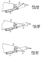
- a conventional airfoil 70 is provided with an associated conventional control surface 72 which is moved between elevated (Fig. 10A), neutral (Fig. 10B), and downwardly deflected (Fig. 10C) positions as a result of operation of an actuator 74.
- Moment arm in the neutral or undeflected position of the control surface 72 as seen in Fig. 10B is indicated by a reference symbol MA 0 .
- mechanical advantage is inversely proportional to moment arm.
- rotor offset indicated at 76 is at a maximum such that the moment arm of the rotor 28 is at a maximum while the airstream loads are at a minimum.
- the control surface 24 is approximately 75% deflected.
- rotor offset indicated at 78 is reduced from that indicated at 76 with an accompanying reduced moment arm resulting in an improved mechanical advantage.
- the airstream loads are at a maximum while rotor offset indicated at 80 is zero resulting in a maximum, or indeed infinite, mechanical advantage.
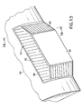
- a flight control system for the aircraft 20 includes elastomeric transition sections 82 joining an airfoil 84 and an associated control surface 86 thereby eliminating any gap between the airfoil and the control surface.
- the elastomeric transition sections 82 include elastomeric material 88 of silicone rubber or other suitable material having a plurality of first and second rods 90, 92, respectively, embedded therein and extending between the airfoil and the control surface, the first rods 90 extending generally spanwise, the second rods 92 extending generally chordwise.
- the rods 90, 92 are preferably composed of a material selected from the group consisting of: fiberglass, graphite, steel and aluminum.
- the elastomeric transition sections 82 also include a plurality of transition couplings 94 pivotally connected, respectively with a plurality of the first rods 90 across the span of the inboard and outboard elastomeric transition sections and of the second rods 92 adjacent the interface between the control surface 86 and the airfoil 84.
- a first control surface 100 is mounted on an airfoil 102 for pivotal movement about a spanwise extending axis generally in the manner described for the control surface 24 and airfoil 22.
- a second control surface 104 is also mounted on the airfoil 102, via the first control surface 100, for pivotal movement about a spanwise extending axis.
- the second control surface 104 is generally parallel with the first control surface and is spaced from the first control surface in the chordwise direction.
- the first and second control surfaces are movable through a range of positions between a neutral position (Fig. 17) at which airstream load thereon is a minimum and an upwardly deflected position, in one instance, and a downwardly deflected position (Fig. 18) in another instance.
- the airstream load on the control surfaces 100, 104 is a maximum when the control surfaces assume either the upwardly deflected position or the downwardly deflected position.
- An operator mechanism 106 is provided for moving the first and second control surfaces 100, 104, respectively, between the upwardly deflected and downwardly deflected positions.
- the operator mechanism 106 includes a pair of spanwise spaced active rotors 108, each rotor mounted on the airfoil 102 for rotation about a chordwise extending rotary axis 110 and having an active horn member 112 with a terminal end 114 offset from the rotary axis.
- a pair of spanwise spaced passive rotors 116 are mounted on the second control surface 104 for rotation about a chordwise extending rotary axis 118.
- Each passive rotor 116 has a passive horn member 120 with a terminal end 122 offset from the rotary axis 118.
- An elongated spanwise extending guide track 124 is associated with each pair of rotors 108, 116 and is integral with, and generally in the plane of, the control surface 100.
- the terminal ends 114, 122 of the active and passive horn members, respectively, are pivotally engaged to one another and both are slidably engaged with the guide track 124.
- a spanwise extending transfer bar 126 connects the two sets of active rotors 108 and passive rotors 116 to assure their unitary movement.
- An actuator not shown in this instance, but generally similar to rotary actuator 48 seen in Fig. 4, is provided with associated shafts and gearing for rotating each active rotor 108 about the rotary axis 110.
- the first and second control surfaces 100, 104 are thereby moved between the upwardly deflected and downwardly deflected positions.
- the mechanical advantage offered by the operator mechanism 106 is maximized when the load of the airstream on the control surfaces 100, 104 is also at a maximum.
- aerodynamics of an aircraft embodying the invention are improved by means of the extending controls which provide greater control power, roll power, and lift power because chord length is directly proportional to lift.
- the invention serves, desirably, to always impart tension to the elastomeric transition members by providing extension along with rotation of the control surface.
Landscapes
- Engineering & Computer Science (AREA)
- Aviation & Aerospace Engineering (AREA)
- Mechanical Engineering (AREA)
- Automation & Control Theory (AREA)
- Toys (AREA)
- Vehicle Body Suspensions (AREA)
- Transmission Devices (AREA)
Applications Claiming Priority (2)
| Application Number | Priority Date | Filing Date | Title |
|---|---|---|---|
| US996182 | 1992-12-23 | ||
| US09/996,182 US6467733B1 (en) | 2001-11-28 | 2001-11-28 | Aerodynamic control surface system |
Publications (3)
| Publication Number | Publication Date |
|---|---|
| EP1316501A2 true EP1316501A2 (de) | 2003-06-04 |
| EP1316501A3 EP1316501A3 (de) | 2004-04-28 |
| EP1316501B1 EP1316501B1 (de) | 2006-06-14 |
Family
ID=25542595
Family Applications (1)
| Application Number | Title | Priority Date | Filing Date |
|---|---|---|---|
| EP02258426A Expired - Lifetime EP1316501B1 (de) | 2001-11-28 | 2002-11-22 | Betätigungssystem für ein aerodynamisches Ruder |
Country Status (6)
| Country | Link |
|---|---|
| US (1) | US6467733B1 (de) |
| EP (1) | EP1316501B1 (de) |
| AT (1) | ATE329825T1 (de) |
| DE (1) | DE60212303T2 (de) |
| IL (1) | IL153055A (de) |
| RU (1) | RU2296694C2 (de) |
Cited By (1)
| Publication number | Priority date | Publication date | Assignee | Title |
|---|---|---|---|---|
| US7931234B2 (en) | 2005-08-17 | 2011-04-26 | Airbus Deutschland Gmbh | Continuous fuselage connection |
Families Citing this family (31)
| Publication number | Priority date | Publication date | Assignee | Title |
|---|---|---|---|---|
| DE102008047793B4 (de) * | 2008-09-17 | 2017-03-30 | Airbus Defence and Space GmbH | Lasteinleitungselement |
| KR101730664B1 (ko) | 2009-02-02 | 2017-04-26 | 에어로바이론먼트, 인크. | 멀티모드 무인 항공기 |
| JP5886201B2 (ja) | 2009-09-09 | 2016-03-16 | エアロバイロメント, インコーポレイテッドAerovironment, Inc. | エレボン制御システム |
| DK3133019T3 (en) | 2009-09-09 | 2019-02-18 | Aerovironment Inc | NOISE DEVICE FOR A DRONE PROTECTION PIPE |
| US9205912B2 (en) * | 2009-11-04 | 2015-12-08 | John McMurray Clark | Compound motion structure |
| DE102009051983A1 (de) | 2009-11-05 | 2011-05-12 | Airbus Operations Gmbh | Tragflügel eines Flugzeugs |
| US8695925B2 (en) * | 2010-12-15 | 2014-04-15 | The United States Of America As Represented By The Administrator Of The National Aeronautics And Space Administration | Elastically deformable side-edge link for trailing-edge flap aeroacoustic noise reduction |
| US9227721B1 (en) * | 2011-10-07 | 2016-01-05 | The United States of America as represented by the Administrator of the National Aeronautics & Space Administration (NASA) | Variable camber continuous aerodynamic control surfaces and methods for active wing shaping control |
| US8590834B1 (en) * | 2011-11-14 | 2013-11-26 | The Boeing Company | Aircraft control surface actuation system with helical actuation path |
| IL216345A (en) * | 2011-11-14 | 2017-09-28 | Israel Aerospace Ind Ltd | Wing and the devices for it |
| CN102582825B (zh) * | 2012-02-14 | 2013-12-25 | 西北工业大学 | 一种用于飞机机翼表面的密封机构 |
| US8814100B2 (en) | 2012-04-19 | 2014-08-26 | The Boeing Company | Continuous moldline technology (CMT) elastomeric control surface |
| FR2992629B1 (fr) * | 2012-06-27 | 2014-09-12 | Airbus Operations Sas | Dispositif de liaison mecanique d'une gouverne a un element structural fixe d'aeronef et element de voilure d'aeronef equipe de ce dispositif |
| UA79830U (ru) * | 2013-03-12 | 2013-04-25 | Юрий Григорьевич Сидоренко | Привод управления подвижной аэродинамической поверхностью крыла самолета |
| US10017243B2 (en) * | 2013-09-24 | 2018-07-10 | The Boeing Company | Adaptive trailing edge actuator system and method |
| US9038943B1 (en) * | 2014-04-11 | 2015-05-26 | Ralph F. Morris | Safety aileron system |
| FR3022215B1 (fr) * | 2014-06-13 | 2016-05-27 | Sagem Defense Securite | Actionneur pour surface de vol et ensemble de guidage d'un aeronef comprenant un tel actionneur |
| CN105292443A (zh) * | 2015-11-27 | 2016-02-03 | 深圳飞马机器人科技有限公司 | 一种机翼副翼驱动结构 |
| US9975623B2 (en) * | 2016-03-08 | 2018-05-22 | Northrop Grumman Systems Corporation | Elastomeric transition |
| US11745857B2 (en) | 2016-03-30 | 2023-09-05 | Goodrich Actuation Systems Sas | Aircraft force-fight mechanism |
| EP3225540B1 (de) * | 2016-03-30 | 2020-11-18 | Goodrich Actuation Systems SAS | Kraftkampfabschwächung |
| AU2017356989B2 (en) | 2016-11-11 | 2023-02-16 | Aerovironment, Inc. | Extruded wing protection system and device |
| CN107097936B (zh) * | 2017-05-05 | 2023-07-25 | 深圳市中航电科技有限公司 | 无人机副翼驱动结构 |
| CN107697272A (zh) * | 2017-09-11 | 2018-02-16 | 西安冰果智能航空科技有限公司 | 一种无人机舵面驱动机构 |
| US10773817B1 (en) | 2018-03-08 | 2020-09-15 | Northrop Grumman Systems Corporation | Bi-directional flow ram air system for an aircraft |
| JP7096698B2 (ja) * | 2018-04-23 | 2022-07-06 | 株式会社Subaru | 翼構造体、翼構造体の制御方法及び航空機 |
| EP3858728B1 (de) * | 2020-01-31 | 2024-05-01 | Goodrich Actuation Systems Limited | Klappenbetätigungsanordnung |
| US11247767B2 (en) * | 2020-03-05 | 2022-02-15 | Ruben Leon | Wireless autopilot system |
| US11661175B2 (en) | 2020-03-05 | 2023-05-30 | Ruben Leon | Wireless autopilot system |
| EP4124566A1 (de) * | 2021-07-27 | 2023-02-01 | Airbus Operations, S.L.U. | Bewegliche komponente für flugzeuge |
| CN117985218B (zh) * | 2024-03-21 | 2024-08-16 | 中国科学院工程热物理研究所 | 一种用于飞机机翼的变弯度双模式后缘舵面结构及方法 |
Citations (7)
| Publication number | Priority date | Publication date | Assignee | Title |
|---|---|---|---|---|
| US2670909A (en) | 1950-03-01 | 1954-03-02 | Bell Aircraft Corp | Actuating mechanism for aircraft extensible flaps |
| US3109613A (en) | 1960-11-28 | 1963-11-05 | Mabel Wilson Raspet | Variable-camber airfoil |
| US3944170A (en) | 1974-06-20 | 1976-03-16 | Ltv Aerospace Corporation | Apparatus for producing pivotal movement |
| US4286761A (en) | 1978-08-15 | 1981-09-01 | Vought Corporation | Eccentric actuator |
| US5161757A (en) | 1989-07-31 | 1992-11-10 | The Boeing Company | Extending bent shaft flap drive |
| US5222699A (en) | 1990-04-16 | 1993-06-29 | Ltv Aerospace And Defense Company | Variable control aircraft control surface |
| US5794893A (en) | 1995-06-07 | 1998-08-18 | Northrop Grumman Corporation | Elastomeric transition for aircraft control surface |
Family Cites Families (5)
| Publication number | Priority date | Publication date | Assignee | Title |
|---|---|---|---|---|
| SU1246516A1 (ru) * | 1984-12-17 | 1996-09-20 | С.Г. Джамгаров | Устройство выдвижения закрылка |
| DE3627219A1 (de) * | 1986-08-11 | 1988-02-18 | Eckehart Zehrfeldt | Kraftbetaetigtes scharnier mit integrierter auslenkmechanik |
| US5651513A (en) * | 1995-03-01 | 1997-07-29 | Northrop Grumman Corporation | Linear flap drive system |
| US6244542B1 (en) * | 1999-07-20 | 2001-06-12 | Northrop Grumman Corporation | Rotor driven edge |
| US6270039B1 (en) * | 1999-10-12 | 2001-08-07 | Patria Finavicomp Oy | Hinge for movable control surfaces in an aircraft and a connecting piece to be used with such a hinge |
-
2001
- 2001-11-28 US US09/996,182 patent/US6467733B1/en not_active Expired - Lifetime
-
2002
- 2002-11-22 DE DE60212303T patent/DE60212303T2/de not_active Expired - Fee Related
- 2002-11-22 EP EP02258426A patent/EP1316501B1/de not_active Expired - Lifetime
- 2002-11-22 AT AT02258426T patent/ATE329825T1/de not_active IP Right Cessation
- 2002-11-24 IL IL153055A patent/IL153055A/en not_active IP Right Cessation
- 2002-11-27 RU RU2002131967/11A patent/RU2296694C2/ru not_active IP Right Cessation
Patent Citations (7)
| Publication number | Priority date | Publication date | Assignee | Title |
|---|---|---|---|---|
| US2670909A (en) | 1950-03-01 | 1954-03-02 | Bell Aircraft Corp | Actuating mechanism for aircraft extensible flaps |
| US3109613A (en) | 1960-11-28 | 1963-11-05 | Mabel Wilson Raspet | Variable-camber airfoil |
| US3944170A (en) | 1974-06-20 | 1976-03-16 | Ltv Aerospace Corporation | Apparatus for producing pivotal movement |
| US4286761A (en) | 1978-08-15 | 1981-09-01 | Vought Corporation | Eccentric actuator |
| US5161757A (en) | 1989-07-31 | 1992-11-10 | The Boeing Company | Extending bent shaft flap drive |
| US5222699A (en) | 1990-04-16 | 1993-06-29 | Ltv Aerospace And Defense Company | Variable control aircraft control surface |
| US5794893A (en) | 1995-06-07 | 1998-08-18 | Northrop Grumman Corporation | Elastomeric transition for aircraft control surface |
Cited By (1)
| Publication number | Priority date | Publication date | Assignee | Title |
|---|---|---|---|---|
| US7931234B2 (en) | 2005-08-17 | 2011-04-26 | Airbus Deutschland Gmbh | Continuous fuselage connection |
Also Published As
| Publication number | Publication date |
|---|---|
| DE60212303T2 (de) | 2007-05-16 |
| IL153055A0 (en) | 2003-06-24 |
| ATE329825T1 (de) | 2006-07-15 |
| EP1316501B1 (de) | 2006-06-14 |
| US6467733B1 (en) | 2002-10-22 |
| RU2296694C2 (ru) | 2007-04-10 |
| DE60212303D1 (de) | 2006-07-27 |
| EP1316501A3 (de) | 2004-04-28 |
| IL153055A (en) | 2006-07-05 |
Similar Documents
| Publication | Publication Date | Title |
|---|---|---|
| EP1316501B1 (de) | Betätigungssystem für ein aerodynamisches Ruder | |
| US8844878B2 (en) | High lift system for an aircraft | |
| US7661630B2 (en) | High lift longitudinal axis control system | |
| US6164598A (en) | Adaptive control surface apparatus | |
| EP2630033B1 (de) | Vorrichtung zum betrieb einer flugzeugsteuerfläche | |
| US6145791A (en) | Elastomeric transition for aircraft control surface | |
| US5794893A (en) | Elastomeric transition for aircraft control surface | |
| US5222699A (en) | Variable control aircraft control surface | |
| US7309043B2 (en) | Actuation device positioning systems and associated methods, including aircraft spoiler droop systems | |
| US6244542B1 (en) | Rotor driven edge | |
| EP0230060A1 (de) | Beweglicher Vorflügel mit veränderlichem Profil | |
| EP2808250B1 (de) | Flugzeugklappensystem mit Querruderfunktionalität | |
| EP3301018A1 (de) | System zum antreiben und führen einer multifunktionalen hinterkantensteuerungsoberfläche an einem flugzeug | |
| AU2016278099B2 (en) | Aircraft wing system | |
| AU2016278098B2 (en) | Aircraft wing system | |
| US12208896B2 (en) | Wing for an aircraft | |
| US6000660A (en) | Rotary beam variable stiffness wing spar | |
| CN116890987A (zh) | 用于飞行器的机翼、后缘高升力组件、以及飞行器 | |
| EP1343687B1 (de) | Flugzeugklappensystem | |
| WO1996009955A1 (en) | Linkage to deploy a surface relative to a wing | |
| EP0052240A1 (de) | Betätigungsvorrichtung für Flugzeugsteuerflächen | |
| EP3106385A1 (de) | Flugzeugflügelsystem | |
| Andrews | Slotted variable camber flap | |
| IL142411A (en) | Movable surface on an aircraft |
Legal Events
| Date | Code | Title | Description |
|---|---|---|---|
| PUAI | Public reference made under article 153(3) epc to a published international application that has entered the european phase |
Free format text: ORIGINAL CODE: 0009012 |
|
| AK | Designated contracting states |
Designated state(s): AT BE BG CH CY CZ DE DK EE ES FI FR GB GR IE IT LI LU MC NL PT SE SK TR |
|
| AX | Request for extension of the european patent |
Extension state: AL LT LV MK RO SI |
|
| PUAL | Search report despatched |
Free format text: ORIGINAL CODE: 0009013 |
|
| AK | Designated contracting states |
Kind code of ref document: A3 Designated state(s): AT BE BG CH CY CZ DE DK EE ES FI FR GB GR IE IT LI LU MC NL PT SE SK TR |
|
| AX | Request for extension of the european patent |
Extension state: AL LT LV MK RO SI |
|
| RIC1 | Information provided on ipc code assigned before grant |
Ipc: 7B 64C 9/16 B Ipc: 7B 64C 7/00 B Ipc: 7B 64C 9/02 A |
|
| 17P | Request for examination filed |
Effective date: 20041014 |
|
| AKX | Designation fees paid |
Designated state(s): AT BE BG CH CY CZ DE DK EE ES FI FR GB GR IE IT LI LU MC NL PT SE SK TR |
|
| 17Q | First examination report despatched |
Effective date: 20050113 |
|
| GRAP | Despatch of communication of intention to grant a patent |
Free format text: ORIGINAL CODE: EPIDOSNIGR1 |
|
| GRAS | Grant fee paid |
Free format text: ORIGINAL CODE: EPIDOSNIGR3 |
|
| GRAA | (expected) grant |
Free format text: ORIGINAL CODE: 0009210 |
|
| AK | Designated contracting states |
Kind code of ref document: B1 Designated state(s): AT BE BG CH CY CZ DE DK EE ES FI FR GB GR IE IT LI LU MC NL PT SE SK TR |
|
| PG25 | Lapsed in a contracting state [announced via postgrant information from national office to epo] |
Ref country code: IT Free format text: LAPSE BECAUSE OF FAILURE TO SUBMIT A TRANSLATION OF THE DESCRIPTION OR TO PAY THE FEE WITHIN THE PRESCRIBED TIME-LIMIT;WARNING: LAPSES OF ITALIAN PATENTS WITH EFFECTIVE DATE BEFORE 2007 MAY HAVE OCCURRED AT ANY TIME BEFORE 2007. THE CORRECT EFFECTIVE DATE MAY BE DIFFERENT FROM THE ONE RECORDED. Effective date: 20060614 Ref country code: CZ Free format text: LAPSE BECAUSE OF FAILURE TO SUBMIT A TRANSLATION OF THE DESCRIPTION OR TO PAY THE FEE WITHIN THE PRESCRIBED TIME-LIMIT Effective date: 20060614 Ref country code: CH Free format text: LAPSE BECAUSE OF FAILURE TO SUBMIT A TRANSLATION OF THE DESCRIPTION OR TO PAY THE FEE WITHIN THE PRESCRIBED TIME-LIMIT Effective date: 20060614 Ref country code: BE Free format text: LAPSE BECAUSE OF FAILURE TO SUBMIT A TRANSLATION OF THE DESCRIPTION OR TO PAY THE FEE WITHIN THE PRESCRIBED TIME-LIMIT Effective date: 20060614 Ref country code: FI Free format text: LAPSE BECAUSE OF FAILURE TO SUBMIT A TRANSLATION OF THE DESCRIPTION OR TO PAY THE FEE WITHIN THE PRESCRIBED TIME-LIMIT Effective date: 20060614 Ref country code: AT Free format text: LAPSE BECAUSE OF FAILURE TO SUBMIT A TRANSLATION OF THE DESCRIPTION OR TO PAY THE FEE WITHIN THE PRESCRIBED TIME-LIMIT Effective date: 20060614 Ref country code: SK Free format text: LAPSE BECAUSE OF FAILURE TO SUBMIT A TRANSLATION OF THE DESCRIPTION OR TO PAY THE FEE WITHIN THE PRESCRIBED TIME-LIMIT Effective date: 20060614 Ref country code: LI Free format text: LAPSE BECAUSE OF FAILURE TO SUBMIT A TRANSLATION OF THE DESCRIPTION OR TO PAY THE FEE WITHIN THE PRESCRIBED TIME-LIMIT Effective date: 20060614 |
|
| REG | Reference to a national code |
Ref country code: GB Ref legal event code: FG4D |
|
| REG | Reference to a national code |
Ref country code: CH Ref legal event code: EP |
|
| REG | Reference to a national code |
Ref country code: IE Ref legal event code: FG4D |
|
| REF | Corresponds to: |
Ref document number: 60212303 Country of ref document: DE Date of ref document: 20060727 Kind code of ref document: P |
|
| PG25 | Lapsed in a contracting state [announced via postgrant information from national office to epo] |
Ref country code: DK Free format text: LAPSE BECAUSE OF FAILURE TO SUBMIT A TRANSLATION OF THE DESCRIPTION OR TO PAY THE FEE WITHIN THE PRESCRIBED TIME-LIMIT Effective date: 20060914 |
|
| PG25 | Lapsed in a contracting state [announced via postgrant information from national office to epo] |
Ref country code: ES Free format text: LAPSE BECAUSE OF FAILURE TO SUBMIT A TRANSLATION OF THE DESCRIPTION OR TO PAY THE FEE WITHIN THE PRESCRIBED TIME-LIMIT Effective date: 20060925 |
|
| REG | Reference to a national code |
Ref country code: SE Ref legal event code: TRGR |
|
| REG | Reference to a national code |
Ref country code: GR Ref legal event code: EP Ref document number: 20060402854 Country of ref document: GR |
|
| ET | Fr: translation filed | ||
| PG25 | Lapsed in a contracting state [announced via postgrant information from national office to epo] |
Ref country code: PT Free format text: LAPSE BECAUSE OF FAILURE TO SUBMIT A TRANSLATION OF THE DESCRIPTION OR TO PAY THE FEE WITHIN THE PRESCRIBED TIME-LIMIT Effective date: 20061114 |
|
| PGFP | Annual fee paid to national office [announced via postgrant information from national office to epo] |
Ref country code: FR Payment date: 20061117 Year of fee payment: 5 |
|
| PGFP | Annual fee paid to national office [announced via postgrant information from national office to epo] |
Ref country code: NL Payment date: 20061121 Year of fee payment: 5 |
|
| PG25 | Lapsed in a contracting state [announced via postgrant information from national office to epo] |
Ref country code: IE Free format text: LAPSE BECAUSE OF NON-PAYMENT OF DUE FEES Effective date: 20061122 |
|
| PGFP | Annual fee paid to national office [announced via postgrant information from national office to epo] |
Ref country code: GB Payment date: 20061122 Year of fee payment: 5 |
|
| PGFP | Annual fee paid to national office [announced via postgrant information from national office to epo] |
Ref country code: SE Payment date: 20061124 Year of fee payment: 5 |
|
| PG25 | Lapsed in a contracting state [announced via postgrant information from national office to epo] |
Ref country code: MC Free format text: LAPSE BECAUSE OF NON-PAYMENT OF DUE FEES Effective date: 20061130 |
|
| PGFP | Annual fee paid to national office [announced via postgrant information from national office to epo] |
Ref country code: GR Payment date: 20061130 Year of fee payment: 5 |
|
| REG | Reference to a national code |
Ref country code: CH Ref legal event code: PL |
|
| PGFP | Annual fee paid to national office [announced via postgrant information from national office to epo] |
Ref country code: DE Payment date: 20070102 Year of fee payment: 5 |
|
| PLBE | No opposition filed within time limit |
Free format text: ORIGINAL CODE: 0009261 |
|
| STAA | Information on the status of an ep patent application or granted ep patent |
Free format text: STATUS: NO OPPOSITION FILED WITHIN TIME LIMIT |
|
| 26N | No opposition filed |
Effective date: 20070315 |
|
| PG25 | Lapsed in a contracting state [announced via postgrant information from national office to epo] |
Ref country code: BG Free format text: LAPSE BECAUSE OF FAILURE TO SUBMIT A TRANSLATION OF THE DESCRIPTION OR TO PAY THE FEE WITHIN THE PRESCRIBED TIME-LIMIT Effective date: 20060914 Ref country code: EE Free format text: LAPSE BECAUSE OF FAILURE TO SUBMIT A TRANSLATION OF THE DESCRIPTION OR TO PAY THE FEE WITHIN THE PRESCRIBED TIME-LIMIT Effective date: 20060614 |
|
| EUG | Se: european patent has lapsed | ||
| GBPC | Gb: european patent ceased through non-payment of renewal fee |
Effective date: 20071122 |
|
| PG25 | Lapsed in a contracting state [announced via postgrant information from national office to epo] |
Ref country code: TR Free format text: LAPSE BECAUSE OF FAILURE TO SUBMIT A TRANSLATION OF THE DESCRIPTION OR TO PAY THE FEE WITHIN THE PRESCRIBED TIME-LIMIT Effective date: 20060614 Ref country code: LU Free format text: LAPSE BECAUSE OF NON-PAYMENT OF DUE FEES Effective date: 20061122 |
|
| NLV4 | Nl: lapsed or anulled due to non-payment of the annual fee |
Effective date: 20080601 |
|
| PG25 | Lapsed in a contracting state [announced via postgrant information from national office to epo] |
Ref country code: DE Free format text: LAPSE BECAUSE OF NON-PAYMENT OF DUE FEES Effective date: 20080603 Ref country code: GR Free format text: LAPSE BECAUSE OF NON-PAYMENT OF DUE FEES Effective date: 20060915 Ref country code: NL Free format text: LAPSE BECAUSE OF NON-PAYMENT OF DUE FEES Effective date: 20080601 Ref country code: SE Free format text: LAPSE BECAUSE OF NON-PAYMENT OF DUE FEES Effective date: 20071123 |
|
| REG | Reference to a national code |
Ref country code: FR Ref legal event code: ST Effective date: 20080930 |
|
| PG25 | Lapsed in a contracting state [announced via postgrant information from national office to epo] |
Ref country code: CY Free format text: LAPSE BECAUSE OF FAILURE TO SUBMIT A TRANSLATION OF THE DESCRIPTION OR TO PAY THE FEE WITHIN THE PRESCRIBED TIME-LIMIT Effective date: 20060614 |
|
| PG25 | Lapsed in a contracting state [announced via postgrant information from national office to epo] |
Ref country code: GB Free format text: LAPSE BECAUSE OF NON-PAYMENT OF DUE FEES Effective date: 20071122 |
|
| PG25 | Lapsed in a contracting state [announced via postgrant information from national office to epo] |
Ref country code: FR Free format text: LAPSE BECAUSE OF NON-PAYMENT OF DUE FEES Effective date: 20071130 |
|
| PGFP | Annual fee paid to national office [announced via postgrant information from national office to epo] |
Ref country code: IT Payment date: 20101124 Year of fee payment: 9 |
|
| PG25 | Lapsed in a contracting state [announced via postgrant information from national office to epo] |
Ref country code: IT Free format text: LAPSE BECAUSE OF NON-PAYMENT OF DUE FEES Effective date: 20111122 |