EP1316643A2 - Kalander für eine Papierbahn - Google Patents
Kalander für eine Papierbahn Download PDFInfo
- Publication number
- EP1316643A2 EP1316643A2 EP02025044A EP02025044A EP1316643A2 EP 1316643 A2 EP1316643 A2 EP 1316643A2 EP 02025044 A EP02025044 A EP 02025044A EP 02025044 A EP02025044 A EP 02025044A EP 1316643 A2 EP1316643 A2 EP 1316643A2
- Authority
- EP
- European Patent Office
- Prior art keywords
- jacket
- roll
- calender
- driving
- support
- Prior art date
- Legal status (The legal status is an assumption and is not a legal conclusion. Google has not performed a legal analysis and makes no representation as to the accuracy of the status listed.)
- Withdrawn
Links
Images


Classifications
-
- D—TEXTILES; PAPER
- D21—PAPER-MAKING; PRODUCTION OF CELLULOSE
- D21G—CALENDERS; ACCESSORIES FOR PAPER-MAKING MACHINES
- D21G1/00—Calenders; Smoothing apparatus
- D21G1/006—Calenders; Smoothing apparatus with extended nips
-
- D—TEXTILES; PAPER
- D21—PAPER-MAKING; PRODUCTION OF CELLULOSE
- D21G—CALENDERS; ACCESSORIES FOR PAPER-MAKING MACHINES
- D21G1/00—Calenders; Smoothing apparatus
-
- D—TEXTILES; PAPER
- D21—PAPER-MAKING; PRODUCTION OF CELLULOSE
- D21G—CALENDERS; ACCESSORIES FOR PAPER-MAKING MACHINES
- D21G1/00—Calenders; Smoothing apparatus
- D21G1/0066—Calenders; Smoothing apparatus using a special calendering belt
Definitions
- the present invention relates generally to a calender for a sheet of paper, and more particularly to a calender which performs a surface process on paper after it is dried by a drier, to make it smooth and glossy.
- a layer of paper made by a paper-making section is pressed to remove water by a press . Then, the paper is heated and dried. Next, a calender is employed as a machine in which paper is pressed by rollers to glaze or smooth it.
- Typical examples of calenders are a chilled nip calender, a soft nip calender, and a shoe calender.
- the chilled nip calender is equipped with chilled metal rolls to form at least one pair of nips.
- the soft nip calender is constructed of a metal roll and an elastic resin roll. In the soft nip calender, only a pair of nips is formed on the periphery of the resin roll.
- the shoe calender is constructed of a metal roll, a tube sleeve disposed opposite the metal roll and a shoe which is inside of the tube sleeve. The shoe is pressed against the inner periphery of the sleeve to form a nip.
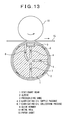
- Figs. 13 and 14 show a first conventional shoe calender described in patent reference 1.
- the conventional shoe calender is constructed of an upper half part including a metal roll 10, and a lower half part including a cylindrical stationary beam 1, a sleeve 2, etc.
- the cylindrical stationary beam 1 is fixedly attached to a support leg 11.
- the outer periphery of the stationary beam 1 is provided with guide members 8 at suitable intervals with respect to the center of the stationary beam 1.
- a sleeve 12 is provided to cover the cylindrical stationary beam 1 and rotatably supported by the guide members 8. The opposite ends of the sleeve 12 are further supported by clamp discs 9 to make the interior airtight.
- the lower half part of the calender with the sleeve 2 is brought into contact with the peripheral surface of the metal roll 10 through the paper sheet 15, as shown in Fig. 13.
- the sleeve 2 is pressurized by applying pressurized oil to the pressurizing shoe 3 and utilizing the deformation of the sleeve 2 that develops when the sleeve 2 is pressed radially outward.
- the stationary beam 1 is further provided with lubricating-oil supply passages 4, 5 and lubricating-oil collection passages 6, 7.
- the first lubricating-oil supply passage 4 is connected to the lower portion of the pressurizing shoe 3 so that pressurizing force is applied to the pressurizing shoe 3.
- the second lubricating-oil supply passage 5 is opened at the outer periphery of the stationary beam 1 so that lubricating oil can be supplied to the inner periphery of the sleeve 2.
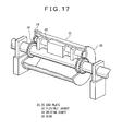
- Figs. 15 through 17 show a second conventional shoe calender described in patent reference 2.
- the conventional shoe calender is basically the same in construction as the first conventional shoe calender shown in Figs. 13 and 14.
- a flexible jacket 32 is pressed against a metal roll 10 to calender a paper sheet 15.
- a shoe roll 30 is pressed against the metal roll 10 by a pressurizing shoe 18 provided inside the flexible jacket 32.
- Reference numeral 95 denotes a pressurizing unit for the metal roll 10.
- Reference numeral 34 denotes a support beam for the pressurizing shoe 18, and 20 denotes a pressurizing unit.
- the opposite ends of the flexible jacket 32 are fixed to end plates 24, 26. If the pressurizing unit 20 is actuated, the pressurizing shoe 18 projects in the radial direction of the flexible jacket 32 and deforms the flexible jacket 32. As a result, the paper sheet 15 is pressurized between the metal roll 10 and the flexible jacket 32.
- the sleeve 2 is rotated by the rotational force of the metal roll 10 which is rotated by a driving unit (not shown) . Because of this, if the pressurizing force of the pressurizing shoe 3 is weak, the transmission of the rotational force will be insufficient, and consequently, the sleeve 2 will slip easily. Conversely, if it is strong, the friction between the pressurizing shoe 3 and the sleeve 2 will increase. As a result, heat will be generated and the sleeve 2 will be elliptically deformed.
- the shoe calender is provided with the lubricating-oil supply passages 5, and lubricating oil is supplied to the inner periphery of the sleeve 2 to prevent generation of heat and perform lubrication.
- the guide members 8 are disposed inside the sleeve 2 to prevent deformation of the sleeve 2.
- the sleeve 2 Because of the gaps between the guide members 8 and the sleeve 2, the sleeve 2 is insufficiently supported and therefore vibrates. As a result, there is a problem that because of the vibration, the trace of vibration will occur in the paper sheet 15.
- the sleeve 2 is of a driven type. That is, the sleeve 2 is rotated by contacting with the metal roll 10.
- paper is passed between the sleeve 2 and the metal roll 10 after the sleeve 2 is contacted with the metal roll 10. Because of this, before paper is passed through, the outer periphery of the sleeve 2 is contacted directly with the high-temperature metal roll 10.
- the outer periphery of the sleeve 2 of the shoe calender is constructed of elastic synthetic resin, if the sleeve 2 of the shoe calender is exposed to high temperature for a long time and rises in temperature, then the quality will degrade and the life will be shortened. Particularly, in such a shoe calender, the nip passage time is long and therefore the contact area (i.e., contact time) between the outer periphery of the sleeve 2 and the metal roll 10 is long. As a result, the temperature of the outer periphery of the sleeve 2 becomes considerably high.
- the sleeve 2 is held away from the metal roll 10 until paper is passed through. In soft nip calenders, such a process is often performed. However, since the sleeve 2 in the conventional shoe calender (patent reference 1) has no driving unit, the sleeve 2 will no longer rotate if it is moved away from the metal roll 10. Therefore, in the case where the sleeve 2 is contacted with the metal roll 10 after paper is passed through, it is necessary to contact the sleeve 2 with the metal roll 10 being rotated. In such a case, paper is broken as soon as the sleeve 2 not being rotated is contacted with paper.
- the sleeve 2 must be held in contact with the metal roll 10 during operation.
- the outer periphery of the sleeve 2 which is constructed of a material whose heat-resisting temperature is low (e.g., polyurethane), will reach a considerably high temperature and degrade quickly.
- the flexible jacket 32 can rotate. That is, the end plate 24 or 26 is driven by a driving unit (not shown). A gear 56 is rotated by a driving shaft 48. In this way, the flexible jacket 32 is rotated. Since the moving speed of the paper sheet 15 can be synchronized with the rotational speed of the flexible jacket 32, breaking of the paper sheet 15 can be reduced.
- the pressurizing shoe 18 contacts with the metal roll 10 at one point on the flexible jacket 32. Therefore, in combination with centrifugal force, etc., the flexible jacket 32 is elliptically deformed when it rotates.
- a calender for a sheet of paper comprising a metal roll which is rotated by a first driving unit.
- the calender further comprises a rotatable cylindrical jacket, a pressurizing shoe, and a plurality of support members.
- the cylindrical jacket is disposed opposite the metal roll to form a calender nip so that the sheet of paper is continuously passed through the calender nip.
- the pressurizing shoe is provided within the jacket at the position of the calender nip and presses the interior surface of the jacket radially outward to pressurize the calender nip.
- the support members are disposed inside the jacket so that they are equally balanced in the peripheral direction of the jacket.
- a plurality of support members are disposed inside the jacket so that they are equally balanced in the peripheral direction of the jacket. With the support members equally balanced in the peripheral direction of the jacket, deformation of the jacket due to rotation of the jacket can be prevented, and the occurrence of vibration due to the jacket deformation can be prevented.
- each of the support members comprises a shoe. At the position opposite to one of the support shoes through the jacket, there is provided a driving roll which is pressed against the jacket to rotate the jacket.
- the driving roll is disposed at the position opposite to the support shoe through the jacket. Since the jacket is supported at the inner and outer peripheries, deformation during rotation is reliably prevented. In addition, because the jacket is rotated by the driving roll, driving force is assured even if there is a gap between the metal roll and the jacket when a sheet of paper is passed between the metal roll and the jacket. As a result, a sheet of paper can be easily passed between the metal roll and the jacket.
- the support shoe comprises a plurality of divided type shoes divided an axial direction.
- the support shoe is divided into small shoes.
- the contact area between the support shoes and the jacket is reduced and the friction resistance is reduced. Therefore, the driving load of the second driving unit can be reduced and the power of the second driving unit can be saved.
- a surface of the support shoe is provided with grooves which extend in a direction where the jacket rotates.
- the support shoe is provided with grooves which extends in a direction where the jacket rotates, the lubricating oil that is sprayed inside the jacket flows through the grooves. As a result, there is no possibility that the lubricating oil will stay in the bottom of the jacket. Thus, the jacket is more smoothly rotated.
- a surface of the support shoe is provided with grooves which extend obliquely with respect to a direction where the jacket rotates.
- the support shoe is provided with oblique grooves, the lubricating oil that is sprayed inside the jacket flows through the oblique grooves. As a result, there is no possibility that the lubricating oil will stay in the bottom of the jacket. Thus, the jacket is more smoothly rotated.
- one of the support members comprises a rotatable roll.
- a driving roll which is pressed against the jacket to rotate the jacket.
- the driving roll is disposed at the position opposite to the support shoe through the jacket. Since the jacket is supported at the inner and outer peripheries, deformation during rotation is reliably prevented. In addition, because the jacket is rotated by the driving roll, driving force is assured even if there is a gap between the metal roll and the jacket when a sheet of paper is passed between the metal roll and the jacket. As a result, a sheet of paper can be easily passed between the metal roll and the jacket. Furthermore, since the support member is constructed of a rotatable roll, the friction resistance with the jacket is reduced. As a result, the driving load of the second driving unit can be reduced and power can be saved.
- the support roll comprises a plurality of divided type rolls divided an axial direction.
- the support roll is divided into small rolls, the contact area between the support rolls and the jacket is reduced and the friction resistance is reduced. Therefore, the driving load of the second driving unit can be reduced and the power of the second driving unit can be saved.
- the outer periphery of the support roll is provided with grooves which extend in the peripheral direction.
- the outer periphery of the support roll is provided with grooves which extend in the circumferental direction, the lubricating oil that is sprayed inside the jacket flows through the grooves. As a result, there is no possibility that the lubricating oil will stay in the bottom of the jacket. Thus, the jacket is more smoothly rotated.
- the outer periphery of the support roll is provided with grooves which extend in spiral form.
- the lubricating oil that is sprayed inside the jacket flows through the spiral grooves. As a result, there is no possibility that the lubricating oil will stay in the bottom of the jacket. Thus, the jacket is more smoothly rotated.
- the driving roll comprises a plurality of divided type rolls divided in an axial direction.
- the driving roll is divided into small rolls, the size is reduced. As a result, power of the driving motor for rotating the driving roll can be saved.
- a doctor blade which abuts the jacket, at the position opposite to one of the support members through the jacket.
- the doctor blade is disposed at the position opposite to the support shoe through the jacket. Because the jacket is supported at the inner and outer peripheries, deformation during rotation is reliably prevented. Furthermore, since dust on the surface of the jacket is removed, the calender effect can be further enhanced.
- the doctor blade comprises a plurality of divided type doctor blades divided in an axial direction of the jacket.
- doctor blade Since the doctor blade is divided into small doctor blades, the contact area between the doctor blades and the jacket is reduced. Therefore, wear on the jacket can be saved.
- the doctor blades are slidable in the axial direction of the jacket.
- doctor blades are slidable in the axial direction of the jacket, dust on the entire surface of the jacket can be removed even if the contact area between the doctor blade and the jacket is reduced. As a result, power can be saved and wear can be prevented.
- the calender further comprises (1) a roll-moving unit for moving the jacket, the driving roll, and the doctor blade between a first position where the jacket is pressed against the metal roll and a second position where the jacket, the driving roll, and the doctor blade are moved away from the metal roll, and (2) a controller for controlling the roll-moving unit and a second driving unit which drives the driving roll.
- the controller controls the roll-moving unit so that until speed of the jacket is synchronized with speed of the metal roll, the jacket is held at the second position.
- the controller also controls speed of the second driving unit so that the speed of the jacket is synchronized with the speed of the metal roll.
- the controller controls the roll-moving unit so that after the speed of the jacket is synchronized with the speed of the metal roll, the jacket is held at the first position.
- the controller performs drooping control on the second driving unit after the jacket is held at the first position.
- the jacket is held at the second position until speed of the jacket is synchronized with speed of the metal roll. Therefore, heating of the jacket is prevented and heat degradation is prevented. Furthermore, drooping control is performed on the second driving unit after the jacket is held at the first position. Therefore, a paper sheet can be stably traveled.
- the controller controls driving torque of the second driving unit to perform load allotment control with the first driving unit as a master side, after pressurization by the pressurizing shoe is performed at the position of the calender nip.
- the controller allots a load on the second driving unit to the first driving unit and gradually reduces the driving torque of the second driving unit to zero, if the load allotment between the first driving unit and the second driving unit is stabilized.
- the controller controls driving torque of the second driving unit to perform load allotment control with the first driving unit as a master side.
- the controller gradually reduces the driving torque of the second driving unit to zero. As a result, a sudden change in the driving torque that is applied to a paper sheet of paper is avoided and cutting of the paper sheet is prevented.
- the controller disconnects the driving roll from the jacket after the driving torque of the second driving unit is gradually reduced to zero, and then stops the speed of the second driving unit.
- the output load and control load of the second driving unit can be saved.
- a calender constructed in accordance with a first embodiment of the present invention.
- a rotatable metal roll 10 and a pressurizing roll 100 are disposed at the opposite positions through a paper sheet 15.
- the outer periphery of the pressurizing roll 100 is provided with a resin jacket 101. Inside the jacket 101, there is provided a stationary base 102.
- a recessed, pressurizing shoe 105 and support shoes 106 and 107 are provided on the base 102 for the purpose of forming a pressuring nip (calender nip) for a calendering process.
- the pressurizing shoe 105 and support shoes 106, 107 are disposed at three positions shifted 120 degrees from each other so that they are equally balanced. Note that the pressurizing force of the pressurizing shoe 105 and the pressurizing forces of the support shoes 106,107 can be independently adjusted.
- the resin jacket 101 is supported at its outer periphery by a driving roll 130 disposed opposite the second support shoe 107.
- the resin jacket 101 is rotated by rotation of the driving roll 130.
- a doctor blade 120 is disposed opposite the first support shoe 106 shifted 120 degrees from the second support shoe 107, and contacts the surface of the jacket 101 to remove paper dust adhering to the surface of the jacket 101.
- the driving roll 130 extends over the entire axial length of the pressurizing roll 100 and is rotated by a driving motor 150. The rotation of the driving roll 130 causes the pressurizing roll 100 to rotate.
- the doctor blade 120 as shown in Fig. 3, is constructed of a stationary doctor blade extending over the entire length of the pressurizing roll 100.
- the doctor blade 120 abuts the surface of the jacket 101 at the position opposite to the first support shoe 106 to hold the jacket 101.
- the support shoes 106, 107 protrude outward in the radial direction of the jacket 101 at the same time so that the circular shape of the jacket 101 is held.
- the driving roll 130 and doctor blade 120 act on the outer periphery of the jacket 101 to prevent deformation. As a result, the jacket 101 can be held in a state near to a circle.
- the calender of the first embodiment is equipped with a driving motor (second driving motor) 150 which drives the driving roll 130 that rotates the jacket 100, and a roll-moving unit 160 which moves the jacket 101 between a first position where the jacket 101 is pressed against the metal roll 10 and a second position where the jacket 101 is moved away from the metal roll 10.
- the calender is also equipped with a driving motor (first driving motor) 12 which drives the metal roll 10.
- the motor 12 for driving the metal roll 10 will hereinafter be referred to as a first driving motor.
- the motor 150 for driving the driving roll 130 will hereinafter be referred to as a second driving motor.
- the first driving motor 12 functions as a master motor
- the second driving motor 150 functions as a helper motor.
- the roll-moving unit 160 is constructed, for example, of fluid pressure cylinders such as hydraulic cylinders and air cylinders, which are provided on the opposite ends of a center shaft 104 which is the center shaft of the pressurizing roll 100 and on the opposite ends of a center shaft 137 which is the center shaft of the driving roll 130. If the jacket 101 and the driving roll 130 are moved toward and away from the metal roll 10 by the fluid pressure cylinders (see vertical arrows in Fig. 2), the jacket 101 can be moved between a first position where the jacket 101 is pressed against the metal roll 10 and a second position where the jacket 101 is moved away from the metal roll 10. Similarly, the doctor blade 120 can be moved in an up-and-down direction by the roll-moving unit 160 (see vertical arrows in Fig. 3).
- fluid pressure cylinders such as hydraulic cylinders and air cylinders
- the second driving motor 150 and roll-moving unit 160 are controlled.
- the controller (control means) 170 also controls the first driving motor 12 that drives the metal roll 10. However, a description will be given of how the second driving motor 150 and roll-moving unit 160 are controlled by the controller 170.
- the controller 170 controls the speed of the second driving motor 150. That is, the rotational speed of the second driving motor 150 is synchronized with the rotational speed of the first driving motor 12 serving as a master motor. More specifically, the peripheral speed of the outer periphery of the jacket 101 is synchronized with the peripheral speed of the outer periphery of the metal roll 10 by the driving roll 130. At the second position, direct contact between the high-temperature metal roll 10 and the jacket 101 is avoided because the jacket 101 is held away from the metal roll 10.
- the problem of the heating of the jacket 101 by the metal roll 10 is overcome. As a result, heat degradation of the jacket 101 is prevented. Even if the heat-resisting temperature of an elastic synthetic resin layer (e.g., a polyurethane resin layer) mounted on the exterior layer of the jacket 101 is low, the exterior layer will not reach the heat-resisting temperature. Thus, the durability of the exterior layer of the jacket 101 can be enhanced.
- an elastic synthetic resin layer e.g., a polyurethane resin layer
- the roll-moving unit 160 is operated so that the jacket 101 is pressed against the metal roll 10.
- the rotational speed of the jacket 101 is equal to that of the metal roll 10
- the second driving motor 150 is droop-controlled.
- the drooping control if a load current through the second driving motor 150 increases, the speed of the second driving motor 150 is decreased. That is, a load on the second driving motor 150 is stabilized by controlling the speed of the second driving motor 150. Since the drooping control stabilizes the allotment of a driving load between the first driving motor 12 and the second driving motor 150, the paper sheet 15 can be stably passed between the metal roll 10 and the jacket 101.
- the paper sheet 15 is pressurized by the pressurizing shoe 105. Thereafter, the drooping control change to torque control.
- Torque control is performed to change the load allotment (torque allotment) between the second driving motor 150 and the first driving motor 12.
- the torque control is the control of changing the load allotment between the second driving motor 150 and the first driving motor 12.
- the load allotment of the second driving motor 150 of the jacket 101 is reduced, while the load allotment of the first driving motor 12 is increased by the amount of the reduced load allotment of the second driving motor 150.
- the driving torque of the second driving motor 150 is gradually reduced to zero (typically for one to two minutes).
- the torque control is performed after stabilization of the load allotment, the torque control is prevented from being performed when the load allotment is unstable. Therefore, a sudden change in the driving torque applied from the jacket 101 and metal roll 10 to the paper sheet 15 is avoided, and the breaking of the paper sheet 15 at this stage can be prevented.
- the reduced load is allotted to the first driving motor 12. Therefore, during normal operation, the jacket 101 is driven by the metal roll 10 instead of being driven by the second driving motor 150. As a result, there is an advantage that the load on the second driving motor 150 to drive the jacket 101 can be reduced. There is also an advantage that the control load for rotating the second driving motor 150 in synchronization with rotation of the metal roll 10 can be reduced.
- a one-way clutch which does not transmit torque may be provided between the second driving motor 150 and the driving roll 130.
- the jacket 101 will be driven by the metal roll 10 instead of being driven by the second driving motor 150.
- the jacket 101 can follow the metal roll 10 during normal operation.
- a driving-force transmission line changing mechanism such as a one-way clutch, which changes a driving-force transmission line so that the transmission of a driving force from the second driving motor 150 to the driving roll 130 is cut off and that the jacket 101 is driven by the metal roll 10, if the rotational speed or driving force of the second driving motor 150 is reduced when the jacket 101 is pressed against the metal roll 10.
- the driving roll 130 is rotated by rotation of the jacket 101, and consequently, there is obtained an advantage that the driving roll 130 functions as a support roll that prevents vibration of the jacket 101.
- the driving roll 130 may be moved away from the jacket 101 by the roll-moving unit 160. In such a case, the driving load of the first driving motor 12 can be reduced.
- the driving roll 130 and the doctor blade 120 are moved in the up-and-down direction to nip the paper sheet 15 therebetween.
- the driving roll 130 and the doctor blade 120 do not always need to be moved in the same direction as the pressuring roll 100. For example, they may be moved in a lateral direction.
- Fig. 4 shows the driving roll of a calender constructed in accordance with the second embodiment of the present invention.
- the driving roll 130 in the above-described first embodiment is replaced with a divided type. Since the remaining construction is the same as the first embodiment, a description will be given of different parts. Note in Fig. 4 that the same parts as Fig. 2 are represented by the same reference numerals.
- a driving roll 130 in the second embodiment is constructed of a plurality of rolls 135 divided in the axial direction of a pressurizing roll 100.
- the rolls 135 are rotated by a driving motor 150 through a connecting shaft 136.
- the weight of the rolls 135 of the second embodiment is reduced, compared with the driving roll 130 of the first embodiment.
- power of the driving motor 150 can be saved.
- the jacket 101 is supported at the interior and exterior surfaces thereof by the support shoe 107 and the driving roll 130, vibration of the jacket 101 can be prevented.
- Fig. 5 shows the doctor blade of a calender constructed in accordance with the third embodiment of the present invention.
- the doctor blade 120 in the above-described first embodiment is replaced with a divided type. Since the remaining construction is the same as the first embodiment, a description will be given of different parts. Note in Fig. 5 that the same parts as Fig. 3 are represented by the same reference numerals.
- a doctor blade 120 in the third embodiment is constructed of two doctor blades divided in the axial direction of a pressurizing roll 100.
- the two doctor blades 125 are disposed on a support plate 126 with a space.
- the doctor blades 125 are slid a predetermined quantity in the axial direction of the pressurizing roll 100 by a driving unit M so that paper dust, etc., are removed over the entire surface of the jacket 101 of the pressurizing roll 100.
- the doctor blade 120 is constructed of two divided doctor blades 125. Therefore, the contact area between the doctor blades 125 and the jacket 101 is reduced and wear on the jacket 101 is saved.
- the third embodiment is provided with two doctor blades 125 slidable in the axial direction of the pressurizing roll 100.
- the doctor blade of the present invention may comprise one doctor blade slidable in the axial direction, or it may comprise two or more doctor blades slidable in the axial direction.
- Fig. 6 shows the support shoes of a calender constructed in accordance with the fourth embodiment of the present invention.
- the support shoe 107 in the above-described first embodiment is replaced with a divided type. Since the remaining construction is the same as the first embodiment, a description will be given of different parts. Note in Fig. 6 that the same parts as Fig. 2 are represented by the same reference numerals.
- a support shoe 107 in the fourth embodiment is constructed of 6 support shoes 107a divided in the axial direction of a pressurizing roll 100.
- the support shoes 107a are disposed at predetermined intervals on a pressurizing unit 107b.
- the support shoes 107a support the jacket 101 along with a driving roll 130 disposed at the position opposite to the support shoes 107a through a jacket 101.
- the jacket 101 is rotated by rotation of the driving roll 130.
- the support shoe 107 is constructed of 6 divided support shoes 107a. Therefore, the contact area between the support shoes 107a and the jacket 101 is reduced and wear on the jacket 101 is saved. As a result, the driving load of the driving roll 130 is reduced and the power of the driving motor 150 for driving the driving roll 130 is saved. While the fourth embodiment is provided with 6 support shoes 107a, the present invention is not limited to the 6 support shoes 107a.
- Fig. 7 shows a calender constructed in accordance with the fifth embodiment of the present invention.
- the number of support shoes is increased to support a jacket 101 in a state near to a circle. Since the remaining construction is the same as the first embodiment, a description will be given of different parts. Note in Fig. 7 that the same parts as Fig. 1 are represented by the same reference numerals.
- a rotatable metal roll 10 and a pressurizing roll 100 are disposed at the opposite positions through a paper sheet 15.
- the outer periphery of the pressurizing roll 100 is provided with a resin jacket 101. Inside the jacket 101, there is provided a statinary base 103.
- a recessed, pressurizing shoe 105 and support shoes 106 to 109 are provided on the stationary base 103 for the purpose of forming a pressuring nip (calender nip) for a calendering process.
- the pressurizing shoe 105 and support shoes 106 to 109 are disposed at 5 positions shifted 72 degrees from each other so that they are equally balanced.
- a driving roll 130 which is rotated by a driving motor 150, a rotatable support roll 132 having no driving source, and doctor blades 121 and 122 are disposed at the positions opposite to the support shoes 106 to 109 through the jacket 101, respectively.
- the jacket 101 is reliably pressurized and held. As a result, the vibration, runout, slippage, etc., of the jacket 101 can be prevented.
- a lubricating-oil injection nozzle 140 is provided on the upstream side of the pressurizing shoe 105 to perform lubrication and cooling between the interior surface of the jacket 101 and the pressurizing shoe 105.
- lubricating oil 145 sprayed by the lubricating-oil injection nozzle 140, lubrication is performed between the jacket 101, which rotates while being pressurized and held, and the shoes 105 to 109. As a result, the jacket is smoothly rotated and generation of heat is prevented.
- the fifth embodiment makes high-speed operation possible by preventing the deformation, runout, and vibration of the jacket 101.
- the jacket 101 is pressurized and held at its interior and exterior surfaces, smooth rotation of the jacket 101 is assured and slippage prevention is achieved.
- quality is enhanced.
- the life of the jacket 101 can be prolonged.
- the driving roll 130 or support roll 132 in the fifth embodiment may be an integral type, or a divided type described in the second embodiment, or a combination type of them.
- the doctor blade 121 or 122 in the fifth embodiment may be an integral type described in the first embodiment of Fig. 3, or a divided type described in the third embodiment of Fig. 5, or a combination type of them.
- the support shoe 106, 107, 108, or 109 in the fifth embodiment may be an integral type described in the first embodiment of Fig. 1, or a divided type described in the fourth embodiment of Fig. 6, or a combination type of them.
- drooping control and load allotment control may be performed on the first driving motor 12 and the second driving motor 150 by the roll-moving unit 160 and controller 170.
- the same advantages as the first embodiment can be obtained.
- Figs. 8A and 8B show the contact surfaces of the support rolls of a calender constructed in accordance with the sixth embodiment of the present invention.
- the support shoe in the above-described fifth embodiment of Fig. 7 is provided with grooves. Since the remaining construction is the same as the fifth embodiment, a description will be given of different parts.
- a support shoe 180 shown in Fig. 8A is disposed inside the jacket 101 of Fig. 7 at the position opposite to the driving roll 130 of Fig. 7.
- the outer periphery of the support shoe 180 is provided with grooves 182, which extend in a direction where the above-described jacket 101 rotates.
- a support shoe 181 in Fig. 8B is disposed inside the jacket 101 of Fig. 7 at the position opposite to the driving roll 130 of Fig. 7.
- the outer periphery of the support shoe 181 is provided with grooves 183, which extend obliquely with respect to the direction where the above-described jacket 101 rotates.
- the lubricating oil 145 sprayed by the injection nozzle 140 of Fig. 7 flows through the grooves 182 or 183 formed in the support roll 180 or 181 by rotation of the jacket 101. That is, the lubricating oil 145 can flow smoothly toward the downstream side. Therefore, since the lubricating oil 145 does not stay in the bottom of the jacket 101, smoother rotation of the jacket 101 becomes possible.
- the support shoes 106, 108, and 109 of the fifth embodiment shown in Fig. 7 may also be provided with the above-described grooves 182 or 183.
- the lubricating oil 145 can flow along the entire interior surface of the jacket 101 and therefore smoother rotation of the jacket 101 becomes possible.
- the support shoe 107a of the fourth embodiment of Fig. 6 may be provided with the grooves 182 or 183.
- Fig. 9 shows a calender constructed in accordance with the seventh embodiment of the present invention.
- Fig. 10 shows the support roll of the calender.
- the number of support shoes in the above-described first embodiment is increased to hold a jacket 101.
- a support member is provided with a rotatable roll. Since the remaining construction is the same as the first embodiment, a description will be given of different parts. Note in Figs. 9 and 10 that the same parts as Figs. 1 and 2 are represented by the same reference numerals.
- a rotatable metal roll 10 and a pressurizing roll 100 are disposed at the opposite positions through a paper sheet 15.
- the outer periphery of the pressurizing roll 100 is provided with a resin jacket 101. Inside the jacket 101, there is provided a stationary base 116.
- a recessed, pressurizing shoe 105 and support shoes 106, 108, 109, and a support roll 110 are provided on the stationary base 116.
- the support shoes 106, 108, 109, and a support roll 110 are disposed symmetrically with respect to the pressurizing shoe 105 at 4 positions shifted 90 degrees from each other so that they are equally balanced.
- a driving roll 130 which is rotated by a driving motor 150 is disposed at the position opposite to a support roll 110 through the jacket 101.
- a doctor blade 120 is disposed at the position opposite to the support shoe 106 109 through the jacket 101.
- a lubricating-oil injection nozzle 140 is provided on the upstream side of the pressurizing shoe 105 to perform lubrication and cooling between the interior surface of the jacket 101 and the pressurizing shoe 105, support members 106, 108, 109, 110.
- lubricating oil 145 sprayed by the lubricating-oil injection nozzle 140, lubrication is performed between the jacket 101, which rotates while being pressurized and held, and the pressurizing shoe 105, support members 106, 108, 109, 110.
- the jacket 101 is smoothly rotated and generation of heat is prevented.
- the seventh embodiment of Fig. 9, Fig.10 makes high-speed operation possible by preventing the deformation, runout, and vibration of the jacket 101.
- the jacket 101 is pressurized and held at its interior and exterior surfaces, smooth rotation of the jacket 101 is assured and slippage prevention is achieved.
- the life of the jacket 101 can be prolonged.
- the support member disposed opposite the driving roll 130 is the rotatable roll 110.
- This roll 110 can reduce the friction resistance between itself and the jacket 101 which develops when the jacket 101 is rotated by the driving roll 130. Because the jacket 101 rotates smoothly, the power of the driving motor 150 for driving the driving roll 130 can be saved.
- the seventh embodiment may be provided with the rotatable support shoe 132 at the position opposite to the support shoe 108 through the jacket 101.
- the seventh embodiment may also be provided with the doctor blade 121 at the position opposite to the support shoe 106 through the jacket 101.
- the support shoes 106, 108, and 109 of the seventh embodiment may be provided with the grooves 182 or 183.
- the structure of the support shoes 106, 108, and 109 can be made the same as the structure of the support roll 110.
- drooping control and load allotment control may be performed on the first driving motor 12 and the second driving motor 150 by the roll-moving unit 160 and controller 170.
- the same advantages as the first embodiment can be obtained.
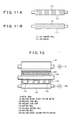
- Figs. 11A and 11B show the support rolls of a calender constructed in accordance with the eighth embodiment of the present invention, respectively.
- the support roll 110 in the above-described seventh embodiment of Fig. 10 is provided with grooves. Since the remaining construction is the same as the seventh embodiment, a description will be given of different parts.
- a support roll 111 shown in Fig. 11A is disposed inside the jacket 101 of Fig. 10 at the position opposite to the driving roll 130 of Fig. 10.
- the outer periphery of the support roll 111 is provided with grooves 113, which extend in the peripheral direction.
- the outer periphery of the support roll 112 is provided with grooves 114, which extend in spiral form.
- the lubricating oil 145 sprayed by the injection nozzle 140 of Fig. 7 flows through the grooves 113 or 114 formed in the support roll 111 or 112 by rotation of the jacket 101. That is, the lubricating oil 145 can flow smoothly toward the downstream side. Therefore, since the lubricating oil 145 does not stay in the bottom of the jacket 101, smoother rotation of the jacket 101 becomes possible.
- Fig. 12 shows the support roll of a calender constructed in accordance with the ninth embodiment of the present invention.
- the support roll 110 in the above-described seventh embodiment is replaced with a divided type. Since the remaining construction is the same as the seventh embodiment, a description will be given of different parts. Note in Fig. 12 that the same parts as Fig. 10 are represented by the same reference numerals.
- a support roll 110 is constructed of rotatable rolls 115 divided in the axial direction of a pressurizing roll 100.
- the support roll 110 is constructed of divided rolls 115. Therefore, the area of the support roll 110 that abuts the above-described jacket 101 is reduced. Since the friction resistance that develops by rotation of the jacket 101 is reduced, a load on the driving roll 130 is reduced and therefore the power of the driving motor 150 for rotating the driving roll 130 can be saved.
- Fig. 12 there are shown five support rolls. However, the number of divided rolls is not limited to the 5 support rolls shown in Fig. 12.
Landscapes
- Paper (AREA)
Applications Claiming Priority (4)
| Application Number | Priority Date | Filing Date | Title |
|---|---|---|---|
| JP2001345878 | 2001-11-12 | ||
| JP2001345878 | 2001-11-12 | ||
| JP2002285832A JP2003213590A (ja) | 2001-11-12 | 2002-09-30 | 紙シートのカレンダ装置 |
| JP2002285832 | 2002-09-30 |
Publications (2)
| Publication Number | Publication Date |
|---|---|
| EP1316643A2 true EP1316643A2 (de) | 2003-06-04 |
| EP1316643A3 EP1316643A3 (de) | 2003-11-26 |
Family
ID=26624475
Family Applications (1)
| Application Number | Title | Priority Date | Filing Date |
|---|---|---|---|
| EP02025044A Withdrawn EP1316643A3 (de) | 2001-11-12 | 2002-11-11 | Kalander für eine Papierbahn |
Country Status (3)
| Country | Link |
|---|---|
| US (3) | US6837157B2 (de) |
| EP (1) | EP1316643A3 (de) |
| JP (1) | JP2003213590A (de) |
Cited By (5)
| Publication number | Priority date | Publication date | Assignee | Title |
|---|---|---|---|---|
| DE102004044389A1 (de) * | 2004-09-14 | 2006-03-30 | Voith Paper Patent Gmbh | Kalanderanordnung |
| WO2007144841A1 (en) * | 2006-06-13 | 2007-12-21 | The Procter & Gamble Company | A process for controlling torque in a calendering system |
| WO2007144840A1 (en) * | 2006-06-13 | 2007-12-21 | The Procter & Gamble Company | A process for controlling torque in a calendering system |
| EP1997584A3 (de) * | 2007-05-26 | 2009-03-04 | Voith Patent GmbH | Schleifanordnung |
| WO2015072907A1 (en) * | 2013-11-14 | 2015-05-21 | Valmet Aktiebolag | An extended nip roll for use in a nip through which a fibrous web is to be passed |
Families Citing this family (5)
| Publication number | Priority date | Publication date | Assignee | Title |
|---|---|---|---|---|
| US20090045029A1 (en) * | 2007-08-16 | 2009-02-19 | Deur Delwyn G | Conveyor roller and cartridge bearing assembly for same |
| CN104190756B (zh) * | 2014-08-13 | 2017-08-04 | 江苏沃林胶辊机械有限公司 | 辊体挠性变形校正装置 |
| CN104190751B (zh) * | 2014-08-13 | 2016-06-08 | 崇州广益机械制造有限公司 | 一种用于校正旋转辊体挠性变形并带有平衡装置的装置 |
| CN104174710B (zh) * | 2014-08-13 | 2017-05-17 | 林文财 | 一种带有平衡装置的辊体挠性校正装置 |
| US11006011B2 (en) * | 2017-05-01 | 2021-05-11 | Hewlett-Packard Development Company, L.P. | Conditioner modules with calender rollers |
Family Cites Families (13)
| Publication number | Priority date | Publication date | Assignee | Title |
|---|---|---|---|---|
| DE3102526C2 (de) * | 1981-01-27 | 1985-05-23 | J.M. Voith Gmbh, 7920 Heidenheim | Preßeinrichtung zum Entwässern von Bahnen, insbesondere Papierbahnen |
| DE3317456C2 (de) * | 1983-04-02 | 1993-12-02 | Voith Gmbh J M | Bandpreßeinheit zum Entwässern von Faserstoffbahnen |
| DE3317457A1 (de) * | 1983-05-13 | 1984-11-15 | J.M. Voith Gmbh, 7920 Heidenheim | Presseinrichtung fuer bandfoermiges gut, insbesondere zum entwaessern einer papierbahn |
| US4673461A (en) * | 1985-11-25 | 1987-06-16 | Beloit Corporation | Enclosed shoe press with flexible end connections for its annular belt |
| FI82274C (fi) * | 1989-03-30 | 1991-02-11 | Valmet Paper Machinery Inc | Foerfarande foer varmpressning och torkningsanordning. |
| FI93755C (fi) * | 1993-07-07 | 1995-05-26 | Valmet Paper Machinery Inc | Paperikoneen imutela |
| EP0741016A3 (de) * | 1995-05-05 | 1997-09-24 | Pretto De Escher Wyss Srl | Presswalze |
| FI2920U1 (fi) * | 1997-02-28 | 1997-05-29 | Valmet Corp | Järjestely kuormituskengillä varustetussa taipumakompensoidussa telassa |
| DE19816235A1 (de) * | 1998-04-11 | 1999-10-14 | Voith Sulzer Papiertech Patent | Antrieb |
| DE19816759A1 (de) * | 1998-04-16 | 1999-10-21 | Voith Sulzer Papiertech Patent | Preßanordnung |
| SE9804347D0 (sv) * | 1998-12-16 | 1998-12-16 | Valmet Corp | Method and apparatus for calendering paper |
| SE9804346D0 (sv) | 1998-12-16 | 1998-12-16 | Valmet Corp | Method and apparatus for calendering paper |
| DE19860735A1 (de) * | 1998-12-30 | 2000-07-06 | Voith Sulzer Papiermasch Gmbh | Schaber |
-
2002
- 2002-09-30 JP JP2002285832A patent/JP2003213590A/ja active Pending
- 2002-11-11 EP EP02025044A patent/EP1316643A3/de not_active Withdrawn
- 2002-11-12 US US10/291,800 patent/US6837157B2/en not_active Expired - Fee Related
-
2004
- 2004-09-21 US US10/944,747 patent/US7134388B2/en not_active Expired - Fee Related
-
2006
- 2006-10-10 US US11/544,730 patent/US20070028786A1/en not_active Abandoned
Cited By (9)
| Publication number | Priority date | Publication date | Assignee | Title |
|---|---|---|---|---|
| DE102004044389A1 (de) * | 2004-09-14 | 2006-03-30 | Voith Paper Patent Gmbh | Kalanderanordnung |
| WO2007144841A1 (en) * | 2006-06-13 | 2007-12-21 | The Procter & Gamble Company | A process for controlling torque in a calendering system |
| WO2007144840A1 (en) * | 2006-06-13 | 2007-12-21 | The Procter & Gamble Company | A process for controlling torque in a calendering system |
| US7524400B2 (en) | 2006-06-13 | 2009-04-28 | The Procter & Gamble Company | Process for controlling torque in a calendering system |
| EP1997584A3 (de) * | 2007-05-26 | 2009-03-04 | Voith Patent GmbH | Schleifanordnung |
| WO2015072907A1 (en) * | 2013-11-14 | 2015-05-21 | Valmet Aktiebolag | An extended nip roll for use in a nip through which a fibrous web is to be passed |
| CN105683443A (zh) * | 2013-11-14 | 2016-06-15 | 维美德瑞典公司 | 用于在纤维纸幅将经过的压区中使用的延长压辊 |
| US9708767B2 (en) | 2013-11-14 | 2017-07-18 | Valmet Aktiebolag | Extended nip roll for use in a nip through which a fibrous web is to be passed |
| CN105683443B (zh) * | 2013-11-14 | 2018-03-16 | 维美德瑞典公司 | 用于在纤维纸幅将经过的压区中使用的延长压辊 |
Also Published As
| Publication number | Publication date |
|---|---|
| US20050056164A1 (en) | 2005-03-17 |
| EP1316643A3 (de) | 2003-11-26 |
| US7134388B2 (en) | 2006-11-14 |
| US20030089249A1 (en) | 2003-05-15 |
| US20070028786A1 (en) | 2007-02-08 |
| US6837157B2 (en) | 2005-01-04 |
| JP2003213590A (ja) | 2003-07-30 |
Similar Documents
| Publication | Publication Date | Title |
|---|---|---|
| US6164198A (en) | Apparatus for calendering paper | |
| US6837157B2 (en) | Calendar for a sheet of paper | |
| JP4234254B2 (ja) | 繊維ウェブのカレンダ掛け方法 | |
| EP2737125B1 (de) | Papierherstellungsmaschine zur herstellung von tissuepapier und verfahren zum betrieb einer papiermaschine | |
| EP0224428A1 (de) | Geschlossene Breit-Nip-Presse | |
| US4916891A (en) | Open-end rotor spinning machine | |
| US5951824A (en) | Compliant hydrodynamic/hydrostatic shoe for papermaking press | |
| JPH07138896A (ja) | ウエブのスムージング装置 | |
| JPS58203199A (ja) | ロ−ルユニツト | |
| CN102051838A (zh) | 打开辊隙的方法和设备 | |
| CN112497722B (zh) | 压辊组件、拉延设备和用于运行这种压辊组件的方法 | |
| FI116080B (fi) | Kartonkituote ja menetelmä sen valmistamiseksi | |
| JP3372530B2 (ja) | カレンダ装置及びカレンダ装置の操作方法 | |
| JP2006508268A (ja) | 板紙製品とその製法 | |
| US20060118256A1 (en) | Lwc paper product and method of making the same | |
| KR200269087Y1 (ko) | 클러치 브레이크 유니트 | |
| JPH0665888A (ja) | カレンダロール | |
| US7096779B2 (en) | Calender arrangement | |
| US5931770A (en) | Controlled deflection roll bearing pad | |
| JP4499304B2 (ja) | カレンダおよびカレンダ処理方法 | |
| JP4071358B2 (ja) | 誘導発熱ロール駆動装置 | |
| SE513274C2 (sv) | Metod för drift av en pressvals av skotyp och för att starta upp en pappersformerande sektion samt skopress för pressande av en fiberbana | |
| FI4581206T3 (fi) | Tela ja puristinlaite | |
| WO2002068755A2 (en) | Belt calender | |
| JPH1181182A (ja) | ウエブのカレンダー装置及び方法 |
Legal Events
| Date | Code | Title | Description |
|---|---|---|---|
| PUAI | Public reference made under article 153(3) epc to a published international application that has entered the european phase |
Free format text: ORIGINAL CODE: 0009012 |
|
| AK | Designated contracting states |
Designated state(s): AT BE BG CH CY CZ DE DK EE ES FI FR GB GR IE IT LI LU MC NL PT SE SK TR |
|
| AX | Request for extension of the european patent |
Extension state: AL LT LV MK RO SI |
|
| PUAL | Search report despatched |
Free format text: ORIGINAL CODE: 0009013 |
|
| AK | Designated contracting states |
Kind code of ref document: A3 Designated state(s): AT BE BG CH CY CZ DE DK EE ES FI FR GB GR IE IT LI LU MC NL PT SE SK TR |
|
| AX | Request for extension of the european patent |
Extension state: AL LT LV MK RO SI |
|
| RIC1 | Information provided on ipc code assigned before grant |
Ipc: 7D 21F 7/02 B Ipc: 7D 21G 1/00 A |
|
| 17P | Request for examination filed |
Effective date: 20040408 |
|
| AKX | Designation fees paid |
Designated state(s): DE FR GB IT SE |
|
| STAA | Information on the status of an ep patent application or granted ep patent |
Free format text: STATUS: THE APPLICATION IS DEEMED TO BE WITHDRAWN |
|
| 18D | Application deemed to be withdrawn |
Effective date: 20060523 |