EP1316670A2 - Vorrichtung zum statischen Erdbohren - Google Patents
Vorrichtung zum statischen Erdbohren Download PDFInfo
- Publication number
- EP1316670A2 EP1316670A2 EP02025388A EP02025388A EP1316670A2 EP 1316670 A2 EP1316670 A2 EP 1316670A2 EP 02025388 A EP02025388 A EP 02025388A EP 02025388 A EP02025388 A EP 02025388A EP 1316670 A2 EP1316670 A2 EP 1316670A2
- Authority
- EP
- European Patent Office
- Prior art keywords
- linkage
- pawl
- coupling means
- ladder
- ground
- Prior art date
- Legal status (The legal status is an assumption and is not a legal conclusion. Google has not performed a legal analysis and makes no representation as to the accuracy of the status listed.)
- Granted
Links
Images





Classifications
-
- F—MECHANICAL ENGINEERING; LIGHTING; HEATING; WEAPONS; BLASTING
- F16—ENGINEERING ELEMENTS AND UNITS; GENERAL MEASURES FOR PRODUCING AND MAINTAINING EFFECTIVE FUNCTIONING OF MACHINES OR INSTALLATIONS; THERMAL INSULATION IN GENERAL
- F16L—PIPES; JOINTS OR FITTINGS FOR PIPES; SUPPORTS FOR PIPES, CABLES OR PROTECTIVE TUBING; MEANS FOR THERMAL INSULATION IN GENERAL
- F16L55/00—Devices or appurtenances for use in, or in connection with, pipes or pipe systems
- F16L55/16—Devices for covering leaks in pipes or hoses, e.g. hose-menders
- F16L55/162—Devices for covering leaks in pipes or hoses, e.g. hose-menders from inside the pipe
- F16L55/165—Devices for covering leaks in pipes or hoses, e.g. hose-menders from inside the pipe a pipe or flexible liner being inserted in the damaged section
- F16L55/1658—Devices for covering leaks in pipes or hoses, e.g. hose-menders from inside the pipe a pipe or flexible liner being inserted in the damaged section the old pipe being ruptured prior to insertion of a new pipe
-
- E—FIXED CONSTRUCTIONS
- E21—EARTH OR ROCK DRILLING; MINING
- E21B—EARTH OR ROCK DRILLING; OBTAINING OIL, GAS, WATER, SOLUBLE OR MELTABLE MATERIALS OR A SLURRY OF MINERALS FROM WELLS
- E21B17/00—Drilling rods or pipes; Flexible drill strings; Kellies; Drill collars; Sucker rods; Cables; Casings; Tubings
- E21B17/02—Couplings; joints
- E21B17/04—Couplings; joints between rod or the like and bit or between rod and rod or the like
- E21B17/046—Couplings; joints between rod or the like and bit or between rod and rod or the like with ribs, pins, or jaws, and complementary grooves or the like, e.g. bayonet catches
-
- E—FIXED CONSTRUCTIONS
- E21—EARTH OR ROCK DRILLING; MINING
- E21B—EARTH OR ROCK DRILLING; OBTAINING OIL, GAS, WATER, SOLUBLE OR MELTABLE MATERIALS OR A SLURRY OF MINERALS FROM WELLS
- E21B17/00—Drilling rods or pipes; Flexible drill strings; Kellies; Drill collars; Sucker rods; Cables; Casings; Tubings
- E21B17/20—Flexible or articulated drilling pipes, e.g. flexible or articulated rods, pipes or cables
-
- E—FIXED CONSTRUCTIONS
- E21—EARTH OR ROCK DRILLING; MINING
- E21B—EARTH OR ROCK DRILLING; OBTAINING OIL, GAS, WATER, SOLUBLE OR MELTABLE MATERIALS OR A SLURRY OF MINERALS FROM WELLS
- E21B19/00—Handling rods, casings, tubes or the like outside the borehole, e.g. in the derrick; Apparatus for feeding the rods or cables
- E21B19/08—Apparatus for feeding the rods or cables; Apparatus for increasing or decreasing the pressure on the drilling tool; Apparatus for counterbalancing the weight of the rods
- E21B19/086—Apparatus for feeding the rods or cables; Apparatus for increasing or decreasing the pressure on the drilling tool; Apparatus for counterbalancing the weight of the rods with a fluid-actuated cylinder
-
- E—FIXED CONSTRUCTIONS
- E21—EARTH OR ROCK DRILLING; MINING
- E21B—EARTH OR ROCK DRILLING; OBTAINING OIL, GAS, WATER, SOLUBLE OR MELTABLE MATERIALS OR A SLURRY OF MINERALS FROM WELLS
- E21B44/00—Automatic control systems specially adapted for drilling operations, i.e. self-operating systems which function to carry out or modify a drilling operation without intervention of a human operator, e.g. computer-controlled drilling systems; Systems specially adapted for monitoring a plurality of drilling variables or conditions
- E21B44/02—Automatic control of the tool feed
- E21B44/06—Automatic control of the tool feed in response to the flow or pressure of the motive fluid of the drive
-
- E—FIXED CONSTRUCTIONS
- E21—EARTH OR ROCK DRILLING; MINING
- E21B—EARTH OR ROCK DRILLING; OBTAINING OIL, GAS, WATER, SOLUBLE OR MELTABLE MATERIALS OR A SLURRY OF MINERALS FROM WELLS
- E21B7/00—Special methods or apparatus for drilling
- E21B7/04—Directional drilling
- E21B7/046—Directional drilling horizontal drilling
-
- E—FIXED CONSTRUCTIONS
- E21—EARTH OR ROCK DRILLING; MINING
- E21B—EARTH OR ROCK DRILLING; OBTAINING OIL, GAS, WATER, SOLUBLE OR MELTABLE MATERIALS OR A SLURRY OF MINERALS FROM WELLS
- E21B7/00—Special methods or apparatus for drilling
- E21B7/20—Driving or forcing casings or pipes into boreholes, e.g. sinking; Simultaneously drilling and casing boreholes
- E21B7/205—Driving or forcing casings or pipes into boreholes, e.g. sinking; Simultaneously drilling and casing boreholes without earth removal
-
- E—FIXED CONSTRUCTIONS
- E21—EARTH OR ROCK DRILLING; MINING
- E21B—EARTH OR ROCK DRILLING; OBTAINING OIL, GAS, WATER, SOLUBLE OR MELTABLE MATERIALS OR A SLURRY OF MINERALS FROM WELLS
- E21B7/00—Special methods or apparatus for drilling
- E21B7/28—Enlarging drilled holes, e.g. by counterboring
- E21B7/30—Enlarging drilled holes, e.g. by counterboring without earth removal
Definitions
- the invention relates to a device for static manufacture or Widening of earth bores and / or to destroy old pipelines at the a push-pull drive via coupling means on protrusions or in recesses of a linkage attacks with a tool at the end.
- a drilling device of this type is described in German Offenlegungsschrift 196 08 980. It consists of a carriage with a hydraulic piston-cylinder unit, that linearly moves a carriage back and forth. The sledge is with connected to a pawl, which is behind a rung of the Ladder linkage grips and thus the ladder linkage with the drill head accordingly the stroke of the hydraulic piston-cylinder unit is moved forward in the drilling direction. At the end of the stroke, the pawl automatically detaches from the rung and moves it Sledge back to its starting position. Meanwhile, the ladder linkage not fixed and accordingly springs under the influence of the on the drill head front end of the ladder linkage acting soil generally one more or less large piece back.
- the problem underlying the invention is therefore the loss of performance due to the springing back of the linkage during the creation a hole with a clearing head and / or when expanding a pilot hole or with the destructive replacement of a pipeline laid in the ground Avoid using a tool.
- the device according to the invention is provided with at least one boom locking device, which is the boom after each stroke, when the coupling means detaches from the linkage, in of the heading position reached.
- the boom lock consists of two opposing holding jaws or from a pawl, which is after driving over a rod rung automatically lowers and reaches behind the rung until the Rung continues to advance in the next stroke.
- the pawl can be arranged such that they pivot about 180 ° leaves and accordingly their blocking effect in both directions of the ladder linkage unfolded. This is easily possible if, for example, the pawl has two stop surfaces arranged at an angle to one another, between which extends a stop lug with which the pawl in the one or the other direction is supported on a ladder rung.
- the device has at least one a drag pawl, for example a fixed pawl and one in Movable in the longitudinal direction of the linkage, connected to the push and pull drive Feed pawl is provided with two directions of action.
- a drag pawl for example a fixed pawl and one in Movable in the longitudinal direction of the linkage, connected to the push and pull drive Feed pawl is provided with two directions of action.
- pawls can also be arranged in this way, for example, on a pivot axis be that they can be pivoted about 180 ° and accordingly theirs Have an effect in both directions of the boom. This is straightforward possible if the pawls, for example, one or two at an angle to each other have arranged stop surfaces with which they are in one or the another direction in a non-positive or positive connection with the linkage let bring.
- the pawls can be contoured so that they each have at least one sliding surface.
- the sliding surface enables the feed pawl loosely over the linkage during the return movement of the linear drive, for example, slides or towed over the rungs of a ladder linkage until it is in active connection again at the start of the feed movement or engagement with the linkage.
- the pawl and possibly also the feed pawl should be in one Allow the neutral position to lock in order to push the linkage freely back and forth to be able to.
- the pawl is preferably fixed to the device and the feed pawl is preferably arranged on a movable carriage connected to a linear drive.
- a double-acting hydraulic cylinder can serve as the linear drive.
- there can the two cylinder rooms with a pressure source via a hydraulic line each be connected to a 3/4-way valve, between which a shuttle valve is switched with a pressure gauge that measures the current pressure the 3/4-way valve via a control unit when the maximum pressure is reached switches and one or the other hydraulic line with the pressure source combines.
- a cutting carriage and at a distance behind it also a widening or clearing head by a buried in the ground
- Line pipe pulled to first slit the line pipe in the longitudinal direction then with the help of the expanding or clearing head expand the surrounding soil and at the same time with the help of the expanding head pull a new pipe into the ground, then it can become one strong bending stress on the linkage between the cutting carriage and the expanding head.
- the invention remedies this in the form of an articulated connection of the linkage, for example, from at least three joint sections, each over pivot axes running at right angles to one another are connected to one another.
- the linkage preferably consists of individual sections that overlap have a plug-in coupling connected to each other.
- the plug-in coupling is like this procure that they have a certain lateral play and accordingly also a steered Allows drilling along a curved line. This is possible because of itself the lateral play between the individual boom sections added in such a way that drilling on a curved path is possible that has an angle of up to 90 ° bridged.
- the frame of the device is preferably telescopic and can be an end plate own, which is guided over bars in the frame.
- the face plate serves as Support of the device when the clearing head with the help of the linkage a pilot hole or an underground pipe towards the frame is pulled.
- the end plate can be provided with a slide which has an opening in the Faceplate closes.
- the opening in the end plate offers the possibility that the clearing head after going through the pilot hole or an underground Pipe has moved, can completely leave the ground; he kicks it together with the soil and fragments that may have been pushed in front of it an underground pipeline in the space between the face plate and the frame of the device and can be there without impairment the hole he made without further ado of the rod and one Loosen the pull tube.
- a device starting from a starting pit 3 statically driven a hole 2 in the ground 1.
- a push-pull drive 4 in the starting pit 3.
- Its stationary carriage 5 is supported by an end plate 6 on the wall located in the direction of advance of the soil 1 and is held by means of one or more ground anchors 7.
- On the carriage 5, a hydraulic piston-cylinder unit 8 is arranged, one Carriage 9 reciprocated.
- the linkage sections 14 consist of rungs 15 and parallel bars 18th
- each rod section 14 there is a coupling head 19, the one with the penultimate rung and the last rung 17 of the adjacent boom section 14 cooperates.
- the coupling head 19 has a recess 20 provided, which overlaps the last rung 17, while a nose 21 on the coupling head 19 engages in a cutout 24 of the penultimate rung 16 and a nose 22 engages in a cutout 25 in the last rung 17.
- the coupling head is dimensioned so that the connection between neighboring Linkage sections 14 has a certain play that a linkage movement allowed along a curved path.
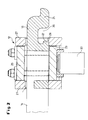
- the linkage lock 12 consists, as shown in Fig. 2, of a frame with a holding jaw 26 and two guide plates 27 with openings 28 for the Ladder linkage 14. Between the plates 27, a jaw 29 is guided, the in time with the advance of the piston 30 of a hydraulic cylinder, not shown is pressed against the linkage.
- FIG. 3 Another linkage lock is shown in Fig. 3; it also consists of a frame with two openings 28 each for the linkage Plates 27 and has a pawl pivotally mounted on an axis 31 32, the stop edge 33 locking against a rod rung sets while a slope 34 of the pawl 32 slides over the rungs.
- each a spar 35 guided linearly movable In the frame 5 of the push-pull drive 4 is at the corner points of a square each a spar 35 guided linearly movable.
- the spars 35 carry the end plate 6, in which there is an opening 36.
- This opening is with the help of a slider 37 closed and allows the passage of one through a pilot hole or buried old pipe pulled clearing head into the free space 38 between the End plate 6 and the frame 5.
- the clearing head can be without particular difficulties from the linkage 14 and one of it in separate the new pipe from the ground, then with a certain protrusion protrudes from the ground and therefore effortlessly with a subsequent Can connect new tube.
- the end plate can be inserted between two after inserting a bolt 39 Extend the rungs with the help of the boom 14.
- the new tube is pulled in with the help of a connection from at least three linkage sections 40, each at an angle of 90 ° to each other extending pivot axes 41 are interconnected (Fig. 5,6). To this There is a gimbal connection between the new tube and the Broaching head, which pulls the front end of the pipe into that of the broaching head earth drilling made much easier.
- a push-pull drive 40 in the starting pit 30 is supported by an end plate 60 on the one located in the direction of advance Wall of the starting pit 30 and is by means of one or more ground anchors 70 held.
- the boom sections 140 are over with the rod section 140 held in the carriage 90 a plug-in coupling connected.
- the linkage sections 140 consist of rungs 150 and parallel bars 180th
- a coupling head is located at the end of each linkage section 140 190, the one with the penultimate rung 160 and the last rung 170 of the neighboring one Linkage section 140 cooperates.
- the coupling head 190 is with a recess 200 which overlaps the last rung 170, while a nose 210 on the coupling head 190 in a cutout 240 of the penultimate Rung 160 and a nose 220 in a cutout 200 on the last rung 170 engages.
- the coupling head is dimensioned so that the connection has some clearance between adjacent linkage sections 140 that allows rod movement along a curved path.
- the pawl 110 is arranged in a fixed position on a boom 250 of the carriage 50 and consists of a swivel arm rotatably mounted on a transverse axis 260 270 with two wings 280,290 arranged in the middle.
- the swivel arm 270 extends over the ladder linkage 140 transverse to the linkage axis and has two each other opposing stop surfaces 300,310, while the wings 280,290 the in the side view of approximately Y-shaped pawl 11 on the end face with stop faces 320,330 and 340,350 with sliding surfaces.
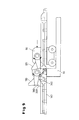
- the feed carriage 90 is structurally corresponding to one of the pawl 110 Feed pawl 120 equipped.
- the pawl 110 is thereby located in operative connection with the linkage section 140 that their stop surface 330 rests on a rung 150.
- the linkage is during the Return movement of the carriage 90 on a movement in the direction of the carriage movement hindered, i.e. locked.
- the feed pawl 120 passes over the rod rungs 150 one after the other in the Way that the sliding surface 340 slides over the individual rungs until the Carriage 90 has reached its starting position and the wing 280 of the feed pawl 120 under the influence of gravity in the window 360 between the rungs 150 and the spars 180 of the linkage falls.
- the pawl 110 slides with its sliding surface 340 over the rungs 150 until it is under the influence of gravity End of the forward stroke with its wings 280 into the window below it 370 falls and the abutment surfaces 310 on both sides meet the bars 180.
- Fig. 10 it is shown how the drilling device from overrun (Fig. 8,9) Train operation is changed. All you need is the pawl 110 and Feed pawl 120 from its position shown in FIGS. 8.9 by approximately 180 ° to be pivoted around the linkage then in the opposite direction to move or lock. This is done in the same way as in overrun mode, but with the difference that now the wings 290 and the stop surfaces 310 and 320 come into effect.
- the linkage can also correspond to the illustrations in FIGS. 11 to 13 be provided with mutually opposite projections 380 attacked by pawls 400 equipped with a claw-like mouth 390.
- the pawls 400 have four wings 410, 420, which have a common one web-like central part 430 are each connected in pairs. Between the web-like middle part 430 and two wings 410,420 is located the mouth 390, which overlaps the rod section 140 in a U-like or claw-like manner.
- the web-like middle part 430 acts as the pivoting movement of the pawl 400 limiting stop.
- the wings 410, 420 also have stop faces 440 and sliding surfaces 450 like the pawls 110, 120.
- a linkage consisting of linkage sections 140 with projections 380 is suitable in the same way as that from the ladder-shaped rod sections 140 existing booms for both the pushing operation and for the Train operation (Fig. 11 to 13). The only difference is that in this If the pawls 400 each have only two opposing stop surfaces on the web-like middle part 430 and four pairs, have front stop surfaces 440 cooperating with the projections 380.
- the linkage as shown in Fig. 14,15 be gimbal-trained.
- the gimbal part of the boom then exists from at least three linkage sections 460, each at an angle pivot axes 470 running at 90 ° to one another are interconnected are. This creates a gimbal connection that is special is suitable for the longitudinal division of a pipeline laid in the ground with With the help of a cutting disc carriage, which is followed by a pulled expansion head is.
- 16 is a linear motor in the form of a double-acting cylinder 80 connected to a piston 480, the cylinder spaces 490,500 via two hydraulic lines 510,520 with a 3/4-way valve 530 are connected to a pressure medium source 540. From the hydraulic line 520 leads a branch line 550 via a shuttle valve 560 to the hydraulic line 510. The shuttle valve 560 is connected via a line 570 to a manometer 580 in connection with a control unit 590, from which two control lines 600,610 lead to the 3/4-way valve 530.
- the automatic control for the feed carriage 90 shown in FIG. 16 works in such a way that the shortly before the dead center position of the piston 480 in the 490,500 pressure increase taking place in both cylinder chambers with the help of the manometer 580 is converted into a signal for the control unit 590, which is then the 3/4-way valve switches over lines 600, 610 so that the cylinder space, in which the pressure increase takes place, supplied with pressure oil and the piston 480 its Takes way in opposite direction.
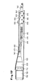
- FIGS. 14, 15 The universal joint linkage of FIGS. 14, 15 is particularly suitable if, for example a cutting disc carriage 620 over a linkage 460,470 with a trailed expanding head 630 is connected, as in the German patent application 198 31 190.7.
- the cutting disc carriage 620 is with three cutting discs 640,650,660 arranged at different heights as well provided with these opposite support rollers 670,680,690.
- the expanding head 630 is used to expand one of the cutting rollers of the cutting carriage 620 and in the longitudinally slotted conduit 700 laid in the ground connected via an articulated coupling 710 to a pull tube 720, the front end into a short protective sleeve 730 connected to the expanding head protrudes.
- the device according to the invention only requires an operator to Insert the individual boom sections and to fold the pawls in the In the event of a reversal of the working direction of the boom; because the blocking and the Feed pawls take their positions at the end of each forward and backward movement of the automatically controlled feed carriage.
- the invention Device is therefore both in terms of their manufacture and in terms of their operating costs are extremely economical.
Landscapes
- Engineering & Computer Science (AREA)
- Geology (AREA)
- Life Sciences & Earth Sciences (AREA)
- Mining & Mineral Resources (AREA)
- Physics & Mathematics (AREA)
- Environmental & Geological Engineering (AREA)
- Fluid Mechanics (AREA)
- General Life Sciences & Earth Sciences (AREA)
- Geochemistry & Mineralogy (AREA)
- Mechanical Engineering (AREA)
- General Engineering & Computer Science (AREA)
- Earth Drilling (AREA)
- Excavating Of Shafts Or Tunnels (AREA)
Abstract
Description
- Fig. 1
- eine Bohrvorrichtung beim erstellen einer Pilotbohrung
- Fig. 2
- eine erfindungsgemäße Gestängearretierung Haltebacken,
- Fig. 3
- eine Gestängearretierung in Gestalt einer einfach wirkenden Sperrklinke,
- Fig. 4
- einen teleskopierbaren Rahmen und
- Fig. 5
- eine kardanische Verbindung in einer Seitenansicht und
- Fig. 6
- in einer Draufsicht;
- Fig. 7
- die Bohrvorrichtung beim Erstellen einer Pilotbohrung,
- Fig. 8
- das Gestänge der Bohrvorrichtung nach Fig. 1 mit dem Schub- und Zugantrieb sowie den beiden Klinken in der Schlußphase der Rückwärtsbewegung im Schubbetrieb,
- Fig. 9
- das Gestänge und den Antrieb am Ende der Vorschubbewegung,
- Fig. 10
- das Verschwenken der Klinken beim Übergang vom Schub- in den Zugbetrieb,
- Fig. 11
- eine Draufsicht auf einen Gestängeabschnitt mit Vorsprüngen und einer Klauenklinke,
- Fig. 12
- eine Seitenansicht des Gestängeabschnitts der Fig. 11,
- Fig. 13
- einen Schnitt nach der Linie VII-VII in Fig. 12,
- Fig. 14
- einen kardanischen Gestängeabschnitt in einer Seitenansicht,
- Fig. 15
- eine Draufsicht auf den Gestängeabschnitt der Fig. 14,
- Fig. 16
- einen Schaltplan zum automatischen Steuern des Linearantriebs für den Klinkenschlitten und
- Fig. 17
- einen Schneidscheibenwagen mit einem nachgezogenen Aufweitkopf.
Claims (20)
- Vorrichtung zum Herstellen oder Aufweiten von Erdbohrungen und/oder zum Zertrümmern alter Rohrleitungen im Erdreich miteinem Rahmen (34),einem Schub- und Zug-Abtrieb (4),einem damit in Antriebsverbindung stehenden leiterartigen Gestänge (14),an den Sprossen des leiterartigen Gestänges angreifenden Kupplungsmitteln (11,12) des Antriebs undeiner Gestängearretierung (12) mit einer Gestängeführung (27) und einem Arretiermittel (26,29;32) an der Führung.
- Vorrichtung nach Anspruch A.1, dadurch gekennzeichnet, dass das Arretiermittel aus einer verschwenkbaren Sperrklinke (32) besteht.
- Vorrichtung nach Anspruch 2, gekennzeichnet durch eine Sperrklinke (32) mit einer Anschlagkante und einer Schräge (34).
- Vorrichtung nach einem der Ansprüche 1 bis 3, gekennzeichnet durch mindestens eine in Gestängeausnehmungen (360,370) oder an Gestängevorsprüngen (380) angreifende Schleppklinke (110,120;400) mit zwei Wirkrichtungen.
- Vorrichtung nach Anspruch 4, gekennzeichnet durch eine ortsfeste Sperrklinke (110) und/oder eine mit dem Antrieb verbundene Vorschubklinke (120;400).
- Vorrichtung nach einem der Ansprüche 1 bis 5, dadurch gekennzeichnet, daß die Klinken (110,120;400) mit Gleitflächen (340,350;450) versehen sind.
- Vorrichtung nach einem der Ansprüche 1 bis 6, dadurch gekennzeichnet, daß die Klinken (110,120) einen Y-förmigen Querschnitt besitzen.
- Vorrichtung nach einem der Ansprüche 1 bis 7, dadurch gekennzeichnet, daß das Gestänge aus einzelnen mit Spiel untereinander gekuppelten Abschnitten (140) besteht.
- Vorrichtung nach einem der Ansprüche 1 bis 8, dadurch gekennzeichnet, daß der Schub- und Zug-Antrieb auf einem Schlitten (90) mit einem Linearantrieb in Gestalt eines doppelt wirkenden Zylinders (80) angeordnet ist.
- Vorrichtung nach Anspruch 9, dadurch gekennzeichnet, daß der Schlitten (90) und/oder der Hydraulikzylinger (80) mit Endschaltern zum Umsteuern des Hydraulikzylinders verbunden ist.
- Vorrichtung nach Anspruch 10, dadurch gekennzeichnet, daß die Hydraulikleitungen (510,520) zu den beiden Zylinderräumen (490,500) des Hydraulikzylinders (480) über ein 3/4-Wegeventil (530) mit einer Druckmittelquelle (540) verbunden sind, und zwischen die Hydraulikleitungen über ein Wechselventil (560) mit einem den jeweils aktuellen Druck messenden Manometer (580) verbunden sind, das über ein Steuergerät (590) beim Erreichen des maximalen Drucks das 3/4-Wegeventil schaltet und dabei die eine oder die andere Hydraulikleitung mit der Druckquelle verbindet.
- Vorrichtung nach einem der Ansprüche 1 bis 11, dadurch gekennzeichnet, daß das Werkzeug (130) über eine gelenkige Verbindung (460,470) mit einem gezogenen Aufweitkopf (630) verbunden ist.
- Vorrichtung nach einem der Ansprüche 1 bis 12, gekennzeichnet durch ein Gestänge mit einer Gelenkverbindung aus mindestens drei Gestängeabschnitten (460), deren einander benachbarte Schwenkachsen (470) jeweils rechtwinklig zueinander verlaufen.
- Vorrichtung nach einem der Ansprüche 4 bis 12, dadurch gekennzeichnet, daß die Klinken (110,120) automatisch verschwenkbar sind.
- Vorrichtung nach einem der Ansprüche 1 bis 14, dadurch gekennzeichnet, daß die Gestängearretierung (12) aus mindestens einer beweglichen Backe und einem feststehenden Gegenstück besteht.
- Gelenkverbundung für ein Leitergestänge (14), gekennzeichnet durch mindestens drei Gestängeabschnitte (40), deren benachbarte Schwenkachsen (41) jeweils rechtwinklig zueinander verlaufen.
- Verfahren zum Herstellen oder Aufweiten von Erdbohrung und/oder zum Zertrümmern oder Erneuern von Rohrleitungen im Erdreich dadurch gekennzeichnet, daß ein leiterartiges Gestänge (14) in das Erdreich eingetrieben wird in dem dieses mit ersten Kupplungsmitteln verbunden wird und mittels der Kupplungsmittel in das Erdreich eingeschoben wird, zweitge Kuplungsmittel mit dem Gestänge verbunden werden, die ersten Kupplungsmittel in ihre Ursprungsposition zurückgefahren und wieder mit dem Gestänge verbunden werden, woraufhin die zweiten Kupplungsmittel wieder gelöst werden.
- Verfahren nach Anspruch 17, dadurch gekennzeichnet, daß das Gestänge aus dem Erdreich gezogen wird, in dem mindestens die ersten Kupplungsmittel in ihrer Wirkrichtung verkehrt werden und die ersten Kupplungsmittel das Gestänge in ihrer Arbeitsphase aus dem Erdreich herausziehen.
- Verfahren nach Anspruch 17 oder 18, dadurch gekennzeichnet, daß Einschieben und Herausziehen automatisch erfolgt.
- Verfahren nach einem der Ansprüche 17 bis 19, gekennzeichnet durch die Verwendung einer Fernsteuerung.
Applications Claiming Priority (5)
| Application Number | Priority Date | Filing Date | Title |
|---|---|---|---|
| DE19814232A DE19814232C1 (de) | 1998-03-30 | 1998-03-30 | Bohrvorrichtung |
| DE19814232 | 1998-03-30 | ||
| DE19849611A DE19849611C1 (de) | 1998-10-28 | 1998-10-28 | Vorrichtung zum statischen Erdbohren |
| DE19849611 | 1998-10-28 | ||
| EP99106469A EP0947663B1 (de) | 1998-03-30 | 1999-03-30 | Vorrichtung zum statischen Erdbohren |
Related Parent Applications (1)
| Application Number | Title | Priority Date | Filing Date |
|---|---|---|---|
| EP99106469A Division EP0947663B1 (de) | 1998-03-30 | 1999-03-30 | Vorrichtung zum statischen Erdbohren |
Publications (3)
| Publication Number | Publication Date |
|---|---|
| EP1316670A2 true EP1316670A2 (de) | 2003-06-04 |
| EP1316670A3 EP1316670A3 (de) | 2004-01-14 |
| EP1316670B1 EP1316670B1 (de) | 2006-10-11 |
Family
ID=26045129
Family Applications (2)
| Application Number | Title | Priority Date | Filing Date |
|---|---|---|---|
| EP02025388A Expired - Lifetime EP1316670B1 (de) | 1998-03-30 | 1999-03-30 | Vorrichtung zum statischen Erdbohren |
| EP99106469A Expired - Lifetime EP0947663B1 (de) | 1998-03-30 | 1999-03-30 | Vorrichtung zum statischen Erdbohren |
Family Applications After (1)
| Application Number | Title | Priority Date | Filing Date |
|---|---|---|---|
| EP99106469A Expired - Lifetime EP0947663B1 (de) | 1998-03-30 | 1999-03-30 | Vorrichtung zum statischen Erdbohren |
Country Status (5)
| Country | Link |
|---|---|
| US (1) | US6238141B1 (de) |
| EP (2) | EP1316670B1 (de) |
| JP (1) | JP3853538B2 (de) |
| CA (1) | CA2267508C (de) |
| DE (2) | DE59913918D1 (de) |
Cited By (1)
| Publication number | Priority date | Publication date | Assignee | Title |
|---|---|---|---|---|
| CN111520074A (zh) * | 2020-06-22 | 2020-08-11 | 安徽建筑大学 | 一种新型水平定向钻穿越冲击回转钻进方法 |
Families Citing this family (11)
| Publication number | Priority date | Publication date | Assignee | Title |
|---|---|---|---|---|
| DE19831190C1 (de) * | 1998-07-11 | 1999-10-28 | Tracto Technik | Vorrichtung und Verfahren zum Längsunterteilen erdverlegter Rohre |
| WO2001040699A1 (de) * | 1999-12-02 | 2001-06-07 | Tracto-Technik Gmbh | Seilzugvorrichtung für berst-/aufweitvorrichtungen |
| DE102005039790B3 (de) * | 2005-08-22 | 2007-01-04 | Tracto-Technik Gmbh | Verfahren und Vorrichtung zum Sanieren erdverlegter Altrohrleitungen |
| EP2824274B1 (de) | 2006-06-16 | 2018-01-31 | Vermeer Manufacturing Company | Mikrotunnelungsystem und -vorrichtung |
| DE102007016823A1 (de) * | 2007-04-05 | 2008-11-06 | Tracto-Technik Gmbh & Co. Kg | Bohrsystem |
| US8256536B2 (en) | 2009-02-11 | 2012-09-04 | Vermeer Manufacturing Company | Backreamer for a tunneling apparatus |
| WO2013019754A2 (en) | 2011-07-29 | 2013-02-07 | Martin Cherrington | Method and portable apparatus for forcing a pipeline into or out of a borehole |
| JP6151305B2 (ja) * | 2015-05-29 | 2017-06-21 | 株式会社ガイナ | 充填材パイルの造成方法および該造成方法に用いる掘削ヘッド |
| CN110645441B (zh) * | 2019-09-26 | 2021-10-01 | 浙江中卓环境科技有限公司 | 一种下水管道非开挖修复装置及其施工方法 |
| CN111119753B (zh) * | 2020-02-25 | 2021-08-31 | 中煤科工集团西安研究院有限公司 | 一种钻杆公接头、自动插接式螺旋钻杆及其施工方法 |
| CN114704200B (zh) * | 2022-06-06 | 2022-08-09 | 山东省烟台地质工程勘察院 | 水工环地质钻探装置 |
Family Cites Families (12)
| Publication number | Priority date | Publication date | Assignee | Title |
|---|---|---|---|---|
| US1210187A (en) * | 1916-05-29 | 1916-12-26 | James E Marquiss | Conduit-forming device. |
| FR819203A (fr) | 1936-06-19 | 1937-10-13 | Bonnet Et Fils | Foreuse horizontale |
| BE757062A (fr) * | 1969-10-10 | 1971-03-16 | Proctor & Schwartz Inc | Transporteur a billes circulantes |
| US4522273A (en) | 1981-05-04 | 1985-06-11 | Larson Leslie N | Drilling rig |
| DE3708616A1 (de) | 1987-03-17 | 1988-09-29 | Schmidt & Co Gmbh Kranz | Anker-bohreinrichtung |
| DE4014775C1 (de) * | 1990-05-09 | 1991-08-01 | Tracto-Technik Paul Schmidt Maschinenfabrik Kg, 5940 Lennestadt, De | |
| US5213449C1 (en) | 1991-07-08 | 2001-07-03 | T Richard Morris | Apparatus for inserting wick drains into the earth |
| US5284404A (en) * | 1992-03-31 | 1994-02-08 | Hu Ming C | Moving steel form system |
| DE19508450C2 (de) * | 1995-03-09 | 1997-03-13 | Tracto Technik | Rammbohrgerät zum zerstörenden Ersetzen erdverlegter Rohrleitungen |
| DE19512076A1 (de) | 1995-04-03 | 1996-10-10 | Klaus Obermann Gmbh | Erd-Bohrgerät |
| DE19608980C2 (de) | 1996-03-08 | 1998-05-07 | Tracto Technik | Vorrichtung zum Bohren im Erdreich |
| US5851096A (en) * | 1997-04-22 | 1998-12-22 | Lackner; Raymond F. | Racheted nut assembly |
-
1999
- 1999-03-30 US US09/281,455 patent/US6238141B1/en not_active Expired - Lifetime
- 1999-03-30 DE DE59913918T patent/DE59913918D1/de not_active Expired - Lifetime
- 1999-03-30 EP EP02025388A patent/EP1316670B1/de not_active Expired - Lifetime
- 1999-03-30 CA CA002267508A patent/CA2267508C/en not_active Expired - Fee Related
- 1999-03-30 EP EP99106469A patent/EP0947663B1/de not_active Expired - Lifetime
- 1999-03-30 JP JP12752099A patent/JP3853538B2/ja not_active Expired - Lifetime
- 1999-03-30 DE DE59912193T patent/DE59912193D1/de not_active Expired - Lifetime
Cited By (1)
| Publication number | Priority date | Publication date | Assignee | Title |
|---|---|---|---|---|
| CN111520074A (zh) * | 2020-06-22 | 2020-08-11 | 安徽建筑大学 | 一种新型水平定向钻穿越冲击回转钻进方法 |
Also Published As
| Publication number | Publication date |
|---|---|
| CA2267508A1 (en) | 1999-09-30 |
| DE59912193D1 (de) | 2005-07-28 |
| EP0947663A1 (de) | 1999-10-06 |
| CA2267508C (en) | 2008-01-29 |
| EP1316670B1 (de) | 2006-10-11 |
| JP3853538B2 (ja) | 2006-12-06 |
| AU722422B2 (en) | 2000-08-03 |
| EP0947663B1 (de) | 2005-06-22 |
| EP1316670A3 (de) | 2004-01-14 |
| AU2250499A (en) | 1999-10-14 |
| US6238141B1 (en) | 2001-05-29 |
| DE59913918D1 (de) | 2006-11-23 |
| JP2000002083A (ja) | 2000-01-07 |
Similar Documents
| Publication | Publication Date | Title |
|---|---|---|
| EP0794315B1 (de) | Vorrichtung zum Bohren im Erdreich | |
| AT403040B (de) | Teleskopierstab | |
| DE3610836C2 (de) | Vorrichtung zum Aneinanderfügen von Rohren | |
| EP1316670B1 (de) | Vorrichtung zum statischen Erdbohren | |
| DE19817872C2 (de) | Aufweitvorrichtung | |
| DE3842081A1 (de) | Bohrgeraet | |
| DE1944988B2 (de) | ||
| EP1580398A1 (de) | Verfahren und Vorrichtung zum Tiefbau | |
| EP0825326B1 (de) | Verfahren und Vorrichtung zum Horizontalbohren und zum Handhaben von Bohrstangen | |
| DE19849611C1 (de) | Vorrichtung zum statischen Erdbohren | |
| DE3238945A1 (de) | Vorrichtung zum setzen von schneestangen oder dgl. | |
| DE102009038383B4 (de) | Rammbohrvorrichtung | |
| DE10011994C1 (de) | Seilzugvorrichtung für Berst-/Aufweitvorrichtungen | |
| EP4263407A1 (de) | Kabeltrommelträger zur drehbaren lagerung einer kabeltrommel | |
| DE2449074A1 (de) | Befestigungsvorrichtung fuer einen bohrer | |
| DE19814232C1 (de) | Bohrvorrichtung | |
| DE102006045557B4 (de) | Gestängemitnehmer | |
| DE10342083B3 (de) | Zugverstärker für eine Horizontalbohranlage | |
| EP0130450B1 (de) | Vorrichtung zum Ziehen von Bohrrohren aus einem Bohrgrund und Lösen der Verschraubung | |
| DE10332328B3 (de) | Vorrichtung zum Erneuern von im Erdreich verlegten Versorgungsleitungen | |
| DE102020005981A1 (de) | Antrieb und Verfahren zum Betreiben eines Antriebs einer Erdbohrvorrichtung | |
| DE19922813C2 (de) | Automatisches Gestänge | |
| DE2106983A1 (de) | Teleskopierbarer Kranausleger | |
| DE19920395C1 (de) | Aufweitvorrichtung | |
| DE102007016824B4 (de) | Eindrehkupplung |
Legal Events
| Date | Code | Title | Description |
|---|---|---|---|
| PUAI | Public reference made under article 153(3) epc to a published international application that has entered the european phase |
Free format text: ORIGINAL CODE: 0009012 |
|
| AC | Divisional application: reference to earlier application |
Ref document number: 0947663 Country of ref document: EP Kind code of ref document: P |
|
| AK | Designated contracting states |
Designated state(s): CH DE FR GB IT LI |
|
| RIN1 | Information on inventor provided before grant (corrected) |
Inventor name: PRUTTI FRANZ Inventor name: PUETTMANN, FRANZ JOSEF Inventor name: KAUFMANN, BERNHARD DIPL.-ING. Inventor name: RIEKES, ANDREAS |
|
| PUAL | Search report despatched |
Free format text: ORIGINAL CODE: 0009013 |
|
| AK | Designated contracting states |
Kind code of ref document: A3 Designated state(s): CH DE FR GB IT LI |
|
| RIC1 | Information provided on ipc code assigned before grant |
Ipc: 7F 16L 55/165 B Ipc: 7E 21B 17/20 B Ipc: 7E 21B 7/30 B Ipc: 7E 21B 7/20 B Ipc: 7E 21B 44/00 B Ipc: 7E 21B 19/083 B Ipc: 7E 21B 17/02 B Ipc: 7E 21B 17/046 A Ipc: 7E 21B 7/04 B |
|
| 17P | Request for examination filed |
Effective date: 20040714 |
|
| 17Q | First examination report despatched |
Effective date: 20040810 |
|
| AKX | Designation fees paid |
Designated state(s): DE GB |
|
| GRAP | Despatch of communication of intention to grant a patent |
Free format text: ORIGINAL CODE: EPIDOSNIGR1 |
|
| GRAS | Grant fee paid |
Free format text: ORIGINAL CODE: EPIDOSNIGR3 |
|
| GRAA | (expected) grant |
Free format text: ORIGINAL CODE: 0009210 |
|
| RAP1 | Party data changed (applicant data changed or rights of an application transferred) |
Owner name: TRACTO-TECHNIK GMBH |
|
| AC | Divisional application: reference to earlier application |
Ref document number: 0947663 Country of ref document: EP Kind code of ref document: P |
|
| AK | Designated contracting states |
Kind code of ref document: B1 Designated state(s): DE GB |
|
| REG | Reference to a national code |
Ref country code: GB Ref legal event code: FG4D Free format text: NOT ENGLISH |
|
| REF | Corresponds to: |
Ref document number: 59913918 Country of ref document: DE Date of ref document: 20061123 Kind code of ref document: P |
|
| GBT | Gb: translation of ep patent filed (gb section 77(6)(a)/1977) |
Effective date: 20070117 |
|
| PLBE | No opposition filed within time limit |
Free format text: ORIGINAL CODE: 0009261 |
|
| STAA | Information on the status of an ep patent application or granted ep patent |
Free format text: STATUS: NO OPPOSITION FILED WITHIN TIME LIMIT |
|
| 26N | No opposition filed |
Effective date: 20070712 |
|
| REG | Reference to a national code |
Ref country code: DE Ref legal event code: R008 Ref document number: 59913918 Country of ref document: DE |
|
| REG | Reference to a national code |
Ref country code: DE Ref legal event code: R039 Ref document number: 59913918 Country of ref document: DE Effective date: 20110728 |
|
| REG | Reference to a national code |
Ref country code: DE Ref legal event code: R081 Ref document number: 59913918 Country of ref document: DE Owner name: TRACTO-TECHNIK GMBH & CO. KG, DE Free format text: FORMER OWNER: TRACTO-TECHNIK GMBH, 57368 LENNESTADT, DE Effective date: 20110929 Ref country code: DE Ref legal event code: R082 Ref document number: 59913918 Country of ref document: DE Representative=s name: KOENIG SZYNKA TILMANN VON RENESSE PATENTANWAEL, DE Effective date: 20110929 |
|
| PG25 | Lapsed in a contracting state [announced via postgrant information from national office to epo] |
Ref country code: DE Free format text: LAPSE BECAUSE OF NON-PAYMENT OF DUE FEES Effective date: 20111001 |
|
| REG | Reference to a national code |
Ref country code: DE Ref legal event code: R097 Ref document number: 59913918 Country of ref document: DE |
|
| REG | Reference to a national code |
Ref country code: DE Ref legal event code: R040 Ref document number: 59913918 Country of ref document: DE Effective date: 20121213 |
|
| PGFP | Annual fee paid to national office [announced via postgrant information from national office to epo] |
Ref country code: GB Payment date: 20180326 Year of fee payment: 20 |
|
| PGFP | Annual fee paid to national office [announced via postgrant information from national office to epo] |
Ref country code: DE Payment date: 20180423 Year of fee payment: 20 |
|
| REG | Reference to a national code |
Ref country code: DE Ref legal event code: R071 Ref document number: 59913918 Country of ref document: DE |
|
| REG | Reference to a national code |
Ref country code: GB Ref legal event code: PE20 Expiry date: 20190329 |
|
| PG25 | Lapsed in a contracting state [announced via postgrant information from national office to epo] |
Ref country code: GB Free format text: LAPSE BECAUSE OF EXPIRATION OF PROTECTION Effective date: 20190329 |