EP1316765A2 - Akkumulator für eine Klimaanlage, insbesondere Fahrzeugklimaanlage - Google Patents
Akkumulator für eine Klimaanlage, insbesondere Fahrzeugklimaanlage Download PDFInfo
- Publication number
- EP1316765A2 EP1316765A2 EP02022058A EP02022058A EP1316765A2 EP 1316765 A2 EP1316765 A2 EP 1316765A2 EP 02022058 A EP02022058 A EP 02022058A EP 02022058 A EP02022058 A EP 02022058A EP 1316765 A2 EP1316765 A2 EP 1316765A2
- Authority
- EP
- European Patent Office
- Prior art keywords
- tube
- housing
- inlet opening
- insert
- refrigerant
- Prior art date
- Legal status (The legal status is an assumption and is not a legal conclusion. Google has not performed a legal analysis and makes no representation as to the accuracy of the status listed.)
- Granted
Links
- 239000003507 refrigerant Substances 0.000 claims abstract description 35
- 230000004888 barrier function Effects 0.000 claims description 8
- 238000004378 air conditioning Methods 0.000 claims description 4
- 244000089486 Phragmites australis subsp australis Species 0.000 description 10
- 239000007788 liquid Substances 0.000 description 7
- 238000004519 manufacturing process Methods 0.000 description 5
- 239000012071 phase Substances 0.000 description 5
- 239000002274 desiccant Substances 0.000 description 4
- 239000003921 oil Substances 0.000 description 4
- 230000001174 ascending effect Effects 0.000 description 3
- 238000003780 insertion Methods 0.000 description 3
- 230000037431 insertion Effects 0.000 description 3
- 239000000203 mixture Substances 0.000 description 3
- 239000002245 particle Substances 0.000 description 3
- 230000000694 effects Effects 0.000 description 2
- 238000005516 engineering process Methods 0.000 description 2
- 238000001704 evaporation Methods 0.000 description 2
- 230000008020 evaporation Effects 0.000 description 2
- 239000007789 gas Substances 0.000 description 2
- 240000003517 Elaeocarpus dentatus Species 0.000 description 1
- 230000002349 favourable effect Effects 0.000 description 1
- 239000007792 gaseous phase Substances 0.000 description 1
- 239000007791 liquid phase Substances 0.000 description 1
- 239000010721 machine oil Substances 0.000 description 1
- 238000000926 separation method Methods 0.000 description 1
- 230000007704 transition Effects 0.000 description 1
- XLYOFNOQVPJJNP-UHFFFAOYSA-N water Substances O XLYOFNOQVPJJNP-UHFFFAOYSA-N 0.000 description 1
Images



Classifications
-
- F—MECHANICAL ENGINEERING; LIGHTING; HEATING; WEAPONS; BLASTING
- F25—REFRIGERATION OR COOLING; COMBINED HEATING AND REFRIGERATION SYSTEMS; HEAT PUMP SYSTEMS; MANUFACTURE OR STORAGE OF ICE; LIQUEFACTION SOLIDIFICATION OF GASES
- F25B—REFRIGERATION MACHINES, PLANTS OR SYSTEMS; COMBINED HEATING AND REFRIGERATION SYSTEMS; HEAT PUMP SYSTEMS
- F25B43/00—Arrangements for separating or purifying gases or liquids; Arrangements for vaporising the residuum of liquid refrigerant, e.g. by heat
- F25B43/006—Accumulators
-
- F—MECHANICAL ENGINEERING; LIGHTING; HEATING; WEAPONS; BLASTING
- F25—REFRIGERATION OR COOLING; COMBINED HEATING AND REFRIGERATION SYSTEMS; HEAT PUMP SYSTEMS; MANUFACTURE OR STORAGE OF ICE; LIQUEFACTION SOLIDIFICATION OF GASES
- F25B—REFRIGERATION MACHINES, PLANTS OR SYSTEMS; COMBINED HEATING AND REFRIGERATION SYSTEMS; HEAT PUMP SYSTEMS
- F25B43/00—Arrangements for separating or purifying gases or liquids; Arrangements for vaporising the residuum of liquid refrigerant, e.g. by heat
- F25B43/003—Filters
Definitions
- the third pipe section which is found in the subject of EP 1 132 696 A1 and through which the refrigerant from the inlet opening the housing is led into the interior of the housing, simply waived.
- the barrier is preferably formed by two wings, which extends radially from the top of the insert extend outside to near the wall of the housing. Through these two wings the upper area of the Interior of the housing divided into two parts, by which one of the inlet opening of the housing and the other of the at least one inlet opening of the first Tube is adjacent. Without complicated shapes in this way the undesired short-circuit flow mentioned of the refrigerant avoided.
- a sieve holding portafilter can be provided.
- the sieve which can be very fine-meshed, serves to Retain particles and possible drops from liquid Refrigerants on the way to the inlet opening of the first tube rise, atomize and on this way to promote their evaporation.
- An embodiment of the invention is particularly preferred, where the second tube has a smaller diameter than the first pipe and inside the first pipe runs. This "nesting" of the two Pipes inside one another are extremely space-saving.
- the downward flow path of the refrigerant runs through the gap in this embodiment between the first and the second tube.
- the refrigerant stands in this way with a suitable choice of the diameter a larger flow cross-section on its descending flow path than on its ascending flow path to disposal. This is due to low flow resistance he wishes.
- the lower ends of the first tube and the second tube can with each other via a bowl-shaped deflection cap be connected, which one to the interior of the housing has leading through opening, wherein the inner surface the deflection cap near the through opening has a profile that leads to a local increase the flow velocity leads.
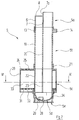
- the housing 2 In the upper part 2a of the housing 2 are, parallel to each other, an inlet bore 3, which widens downwards in a funnel shape, and an outlet bore 4 is provided.
- an insert introduced from below the total with marked with the reference number 5 and below with reference of Figures 2 to 6 is described in more detail.
- the housing 2 After assembly the insert 5, the housing 2 through a bottom 40th tightly closed, which is welded on, for example.
- a spring 41 braced Between the bottom 40 and the insert 5 is a spring 41 braced. This compensates for component tolerances and prevents rattling.
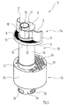
- the insert 5 consists of a head part 5a, a middle part 5b, a receiving part 5c for a desiccant, one bowl-shaped, upwardly opening deflection cap 5d and a lower part 5e composed by Snap connections are releasably connected.
- the separation between the individual parts 5a, 5b, 5c, 5d and 5e is done exclusively according to manufacturing technology Point of view; it has the function of Use 5 basically no influence.
- the upper head part 5a comprises two nested Tubes 6, 7, but not coaxial with each other run. Rather, the tube 7, which is the smaller Has diameter, larger at one point on the tube 6 Diameter; actually the walls of the two pipes 6, 7 together at this point.
- On one-piece cover 8 of the head part 5 closes the outer tube 6; the inner tube 7 pierces the cover 8 upwards and protrudes with an insertion area 7a.
- the outer tube 6 of the head part 5a widens in its lower area to a connecting apron 13, in which the one described below from below Middle part 5b is inserted and locked there.
- a connecting apron 13 To the Connecting apron 13 is in one piece a radially extending Portafilter 14 molded from the bottom of the one wing 9 to the bottom of the other wing 10 runs.
- the cylindrical end face 15 of the In the assembled state, the portafilter 14 lies on the inner lateral surface of the housing 2.
- the filter holder 14 holds a screen 16 which covers the area between the two wings 9, 10, the connecting apron 13 and the cylindrical End face 15 of the filter holder 14 covers.
- Middle part 5b of the insert 5 also has an external one Tube 19 of larger diameter and an inside Tube 20 of smaller diameter, their geometric Arrangement of those of the two tubes 6, 7 in the head part 5a corresponds and which these tubes 6, 7 down continue.
- the length of the middle part 5b can be different long housings can be selected differently.
- the lower end of the middle part 5b is in an after connecting apron 21 extending above the receiving part 5c inserted and locked there.
- the recording part 5c contains the already known arrangement from an outer Tube 22 of larger diameter and an inner tube 23 smaller diameter, which the tubes 19, 20 of Middle part 5b and the pipes 6, 7 of the head part 5a after continue below.
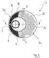
- a flange 24 running radially outwards is formed, which contains a plurality of openings 25.
- the in the plan view circular flange 24 has one Diameter on the inside diameter of the case 2 corresponds. Extends from the outer edge of the flange 24 itself, again integrally formed, a cylindrical Wall 26 down.
- the deflection cap 5d On the lower end of the outer tube 22 of the receiving part 5c is the deflection cap 5d with a connecting apron 27 snapped on.
- the deflection cap 5d connects, similarly the arch of a siphon between the outer tube 22 and the inner tube 23 of the receiving part 5c lying Flow space with the interior of the interior Tube 23.
- a through hole 28 passed through the Inner surface of the deflection cap 5d in the area of a small one Elevation ends. Adjacent to this through hole 28 are two on the inner surface of the deflection cap 5d ribs 29, 30 above (compare in particular FIG 6) integrally formed on the side of the bore 28, the to the between the tubes 22 and 23 of the receiving part 5c lying flow space.
- a radially extending flange 31 from below of the lower part 5e of the insert 5 is inserted and there locked.
- the radially extending flange 31 of the lower part 5e contains in a similar manner to the radial one Flange 24 of the receiving part 5c through holes 23rd
- the radial flanges 24 and 31, the cylinder wall 26 and the outer tube 22 of the receiving part 5c thus delimit an annular receiving space 33, in which a bed of desiccant is introduced can be.
- the entire insert 5 described above will, as already indicated, in the housing 2 shown in Figure 1 of the Accumulator 1 inserted from below.
- the insertion area 7a of the head part 5a of the insert 5 inserted into the outlet opening 4 of the upper housing part 2a.
- the end faces 11, 12 of the wings 9, 10 on Head part 5a of the insert 5 and the end face 15 of the Portafilter 14 of the head part 5a and the outer surface the cylindrical wall 26 of the receiving part 5c lie on the inner surface of the cylinder wall 2b of the housing 2.
- the housing 2 through the Bottom 40 are closed after insertion of spring 41, either screwed into the cylindrical housing wall 2b or welded to it.
- the refrigerant coming from the evaporator which is primarily is in the gas phase, but also liquid Carries refrigerant and oil through it Inlet bore 3 of the housing 2 in the interior of the Housing 2, however, is through the wings 9, 10 on the upper part 5a of the insert 5 prevented "in the short circuit" directly to the inlet openings 17, 18 in the head part 5a of the insert 5 to flow. Instead, the refrigerant "forced down” and gets this way in the area of the openings 25 in the receiving part 5c and from there into the interior 33 of the receiving part 5c and is largely from the desiccant located there freed from water. Part of it seeps through the bottom Openings 32 of the receiving space 33 again.
- the gaseous refrigerant passes through on the way to the Inlet openings 17, 18 of the head part 5a of the insert 5 the sieve 16, with any residues of Liquid particles are atomized very fine, what their residual evaporation facilitated.
- the refrigerating machine oil remains liquid and collects in the liquid refrigerant phase in the lower area of the housing 2 and is through the through hole 28th sucked into the deflection cap 5d. For this, sas overflows gaseous refrigerants deflected by the deflecting cap 5d the through hole 28.
- By the action of the two Ribs 29, 30 that define the flow path of the refrigerant narrow is in the area of the through hole 28 Flow rate increased. This increases the Suction effect of the flowing refrigerant on the liquid Oil / refrigerant mixture, which is below the deflection cap 5d stands and over the window-like openings 36 with the Through hole 28 communicates. The mixture is there carried away and together with the refrigerant from the Accumulator 1 executed.
Landscapes
- Engineering & Computer Science (AREA)
- Chemical & Material Sciences (AREA)
- Analytical Chemistry (AREA)
- Power Engineering (AREA)
- Physics & Mathematics (AREA)
- Mechanical Engineering (AREA)
- Thermal Sciences (AREA)
- General Engineering & Computer Science (AREA)
- Air-Conditioning For Vehicles (AREA)
- Heat-Exchange Devices With Radiators And Conduit Assemblies (AREA)
Abstract
Description
- Figur 1
- einen vertikalen Schnitt durch einen Akkumulator gemäß der Linie I-I von Figur 5;
- Figur 2
- einen Schnitt durch einen in dem Akkumulator von Figur 1 enthaltenen Einsatz in der selben Schnittebene wie Figur 1;
- Figur 3
- einen Schnitt durch den Einsatz der Figur 2, jedoch gemäß Linie III-III von Figur 5;
- Figur 4
- eine perspektivische Ansicht des Einsatzes der Figuren 2 und 3;
- Figur 5
- eine Draufsicht auf den Einsatz der Figuren 2 bis 4;
- Figur 6
- einen horizontalen Schnitt durch den Einsatz der Figuren 2 bis 5 gemäß der Linie VI-VI von Figur 2.
Claims (7)
- Akkumulator für eine nach dem Orifice-Prinzip arbeitende Klimaanlage, insbesondere Fahrzeugklimaanlage, mita) einem Gehäuse, das eine Einlassöffnung und eine Auslassöffnung für Kältemittel aufweist;b) einem in dem Gehäuse anordenbaren Einsatz, der mindestens ein Teil aufweist, in dem einstückig zusammengefasst sind:dadurch gekennzeichnet, dassba) ein erstes, sich im oberen Bereich über mindestens eine Einlassöffnung zum Innenraum des Gehäuses öffnendes, zum Gehäuse ungefähr achsparallel laufendes Rohr;bb) ein zweites zum Gehäuse ungefähr achsparallel verlaufendes Rohr, das an seinem unteren Ende mit dem unteren Ende des ersten Rohres und an seinem oberen Ende mit der Auslauföffnung kommuniziert;c) die Einlassöffnung (3) des Gehäuses (2) direkt ohne Zwischenschaltung eines Rohrabschnittes in den Innenraum des Gehäuses (2) führt;d) an den oberen Bereich (5a) des Einsatzes (5) eine Barriere (9, 10) angeformt ist, welche die direkte Strömung des Kältemittels zwischen der Einlassöffnung (3) des Gehäuses (2) und der mindestens einen Einlassöffnung (17, 18) des ersten Rohres (6, 19, 22) unterbindet.
- Akkumulator nach Anspruch 1, dadurch gekennzeichnet, dass die Barriere (9, 10) von zwei Flügeln (9, 10) gebildet ist, die sich vom oberen Bereich (5a) des Einsatzes (5) radial nach außen bis in die Nähe der Wand (2b) oder bis an die Wand (2b) des Gehäuses (2) erstrecken.
- Akkumulator nach Anspruch 1 oder 2, dadurch gekennzeichnet, dass das erste Rohr (6, 19, 22) an seinem oberen Ende durch einen Deckel (8) verschlossen ist und die mindestens eine Einlassöffnung (17, 18) des ersten Rohres (6, 19, 22) in der Zylinderwand dieses Rohres (6, 19, 22) ausgebildet ist.
- Akkumulator nach einem der vorhergehenden Ansprüche, dadurch gekennzeichnet, dass an dem oberen Bereich (5a) des Einsatzes (5) unterhalb der mindestens einen Einlassöffung (17, 18) auf derjenigen Seite der Barriere (9, 10), die von der Einlassöffnung (3) des Gehäuses (2) abgewandt ist, ein sich radial erstreckender, ein Sieb (16) haltender Siebträger (14) vorgesehen ist.
- Akkumulator nach einem der vorhergehenden Ansprüche, dadurch gekennzeichnet, dass das zweite Rohr (7, 20, 23) einen kleineren Durchmesser als das erste Rohr (6, 19, 22) besitzt und innerhalb des ersten Rohres (6, 19, 22) verläuft.
- Akkumulator nach Anspruch 5, dadurch gekennzeichnet, dass das zweite Rohr (7, 20, 23) exzentrisch innerhalb des ersten Rohres (6, 19, 22) verläuft, derart, dass es entlang einer vertikalen Linie einen gemeinsamen Wandbereich mit dem ersten Rohr (6, 19, 22) besitzt.
- Akkumulator nach einem der Ansprüche 1 bis 6, dadurch gekennzeichnet, dass die unteren Enden des ersten Rohres (6, 19, 22) und des zweiten Rohres (7, 20, 23) über eine schalenförmige Umlenkkappe (5d) miteinander verbunden sind, welche eine zum Innenraum des Gehäuses (2) führende Durchgangsöffnung (28) aufweist, wobei die Innenfläche der Umlenkkappe (5d) in der Nähe der Durchgangsöffnung (28) eine Profilierung (29, 30) besitzt, die zu einer lokalen Erhöhung der Strömungsgeschwindigkeit führt.
Applications Claiming Priority (2)
| Application Number | Priority Date | Filing Date | Title |
|---|---|---|---|
| DE10158409 | 2001-11-29 | ||
| DE2001158409 DE10158409C1 (de) | 2001-11-29 | 2001-11-29 | Akkumulator für eine Klimaanlage, insbesondere Fahrzeugklimaanlage |
Publications (3)
| Publication Number | Publication Date |
|---|---|
| EP1316765A2 true EP1316765A2 (de) | 2003-06-04 |
| EP1316765A3 EP1316765A3 (de) | 2003-10-15 |
| EP1316765B1 EP1316765B1 (de) | 2007-01-03 |
Family
ID=7707297
Family Applications (1)
| Application Number | Title | Priority Date | Filing Date |
|---|---|---|---|
| EP20020022058 Expired - Lifetime EP1316765B1 (de) | 2001-11-29 | 2002-10-02 | Akkumulator für eine Klimaanlage, insbesondere Fahrzeugklimaanlage |
Country Status (2)
| Country | Link |
|---|---|
| EP (1) | EP1316765B1 (de) |
| DE (2) | DE10158409C1 (de) |
Families Citing this family (4)
| Publication number | Priority date | Publication date | Assignee | Title |
|---|---|---|---|---|
| DE102004032279B3 (de) * | 2004-07-02 | 2005-08-18 | Hansa Metallwerke Ag | Akkumulator für eine Klimaanlage, insbesondere Fahrzeug-Klimaanlage |
| DE102004040880B4 (de) * | 2004-08-24 | 2008-03-27 | Jahn Gmbh Umform- Und Zerspanungstechnik | Filtriervorrichtung für einen Kühlmedienkreislauf, insbesondere für eine PKW-Klimaanlage |
| DE102023121627A1 (de) * | 2023-08-11 | 2025-02-13 | Mahle International Gmbh | Akkumulator vorzugsweise für ein Kraftfahrzeug |
| DE102024118467A1 (de) * | 2024-06-28 | 2025-12-31 | Mahle International Gmbh | Vorratsbehälter für einen Kältemittelkreis |
Citations (1)
| Publication number | Priority date | Publication date | Assignee | Title |
|---|---|---|---|---|
| EP1132696A1 (de) | 2000-03-08 | 2001-09-12 | Hansa Metallwerke Ag | Akkumulator für eine nach dem Orifice-Prinzip arbeitende Klimaanlage, insbesondere Fahrzeugklimaanlage |
Family Cites Families (5)
| Publication number | Priority date | Publication date | Assignee | Title |
|---|---|---|---|---|
| US4627247A (en) * | 1986-03-21 | 1986-12-09 | Tecumseh Products Company | Suction accumulator |
| JP2000088402A (ja) * | 1998-07-13 | 2000-03-31 | Showa Alum Corp | アキュムレ―タ |
| ATA124198A (de) * | 1998-07-17 | 1999-10-15 | Plasser Bahnbaumasch Franz | Maschine zum verlegen einer elektrischen oberleitung |
| DE19910775C1 (de) * | 1999-03-11 | 2000-09-28 | Hansa Metallwerke Ag | Akkumulator für eine nach dem "Orifice"-Prinzip arbeitende Klimaanlage, insbesondere Fahrzeugklimaanlage |
| DE19916674C2 (de) * | 1999-04-14 | 2002-02-07 | Hansa Metallwerke Ag | Akkumulator für eine nach dem "Orifice"-Prinzip arbeitende Klimaanlage, insbesondere Fahrzeugklimaanlage |
-
2001
- 2001-11-29 DE DE2001158409 patent/DE10158409C1/de not_active Expired - Fee Related
-
2002
- 2002-10-02 DE DE50209154T patent/DE50209154D1/de not_active Expired - Fee Related
- 2002-10-02 EP EP20020022058 patent/EP1316765B1/de not_active Expired - Lifetime
Patent Citations (1)
| Publication number | Priority date | Publication date | Assignee | Title |
|---|---|---|---|---|
| EP1132696A1 (de) | 2000-03-08 | 2001-09-12 | Hansa Metallwerke Ag | Akkumulator für eine nach dem Orifice-Prinzip arbeitende Klimaanlage, insbesondere Fahrzeugklimaanlage |
Also Published As
| Publication number | Publication date |
|---|---|
| DE50209154D1 (de) | 2007-02-15 |
| EP1316765A3 (de) | 2003-10-15 |
| EP1316765B1 (de) | 2007-01-03 |
| DE10158409C1 (de) | 2003-04-30 |
Similar Documents
| Publication | Publication Date | Title |
|---|---|---|
| DE4245046B4 (de) | Kondensator für eine Klimaanlage eines Fahrzeuges | |
| EP2052136B1 (de) | Vorrichtung zur abscheidung von flüssigkeiten aus gasen | |
| DE4314917C2 (de) | Sammler für Klimaanlagen | |
| EP2129978B1 (de) | Kondensator für eine klimaanlage, insbesondere eines kraftfahrzeuges | |
| EP0191153A2 (de) | Fluidabscheider, insbesondere Gas/Flüssigkeit-Abscheider | |
| DE102005005187A1 (de) | Kondensator für eine Klimaanlage, insbesondere eines Kraftfahrzeuges | |
| DE102008028852A1 (de) | Kältemittelsammler mit Flüssigkeitsabscheider | |
| EP2984421A1 (de) | Sammler | |
| DE2725119C2 (de) | Separatorvorrichtung für Eindampfanlagen | |
| DE19910775C1 (de) | Akkumulator für eine nach dem "Orifice"-Prinzip arbeitende Klimaanlage, insbesondere Fahrzeugklimaanlage | |
| EP1316765B1 (de) | Akkumulator für eine Klimaanlage, insbesondere Fahrzeugklimaanlage | |
| DE10300801B3 (de) | Akkumulator für eine Klimaanlage, insbesondere Fahrzeugklimaanlage | |
| WO2009003884A1 (de) | Kompressor mit flüssigkeitströpfchen zerstäubender einströmkammer | |
| EP1745255A1 (de) | Kondensator für eine klimaanlage, insbesondere für ein kraftfahrzeug | |
| DE102007028591A1 (de) | Akkumulator, insbesondere für eine Kraftfahrzeug- Klimaanlage | |
| DE4230092C2 (de) | Wärmetauscher, insbesondere Verdampfer für Klimaanlagen von Kraftfahrzeugen | |
| DE9219200U1 (de) | Kondensator für eine Klimaanlage | |
| DE10237179B4 (de) | Akkumulator für eine nach dem "Orifice"-Prinzip arbeitende Klimaanlage, insbesondere Fahrzeugklimaanlage | |
| DE8434233U1 (de) | Fluidabscheider, insbesondere Gas/Flüssigkeit-Abscheider | |
| EP1310760A1 (de) | Kältemittelkondensator | |
| DE19946217C1 (de) | Akkumulator für eine nach dem "Orifice"-Prinzip arbeitende Klimaanlage, insbesondere Fahrzeugklimaanlage | |
| DE4245084B4 (de) | Kondensator für eine Klimaanlage eines Fahrzeuges | |
| DE10237178B4 (de) | Akkumulator für eine nach dem "Orifice"-Prinzip arbeitende Klimaanlage, insbesondere Fahrzeugklimaanlage | |
| EP1437562A2 (de) | Akkumulator für eine Klimaanlage, insbesondere Fahrzeugklimaanlage | |
| DE9219184U1 (de) | Kondensator für eine Klimaanlage |
Legal Events
| Date | Code | Title | Description |
|---|---|---|---|
| PUAI | Public reference made under article 153(3) epc to a published international application that has entered the european phase |
Free format text: ORIGINAL CODE: 0009012 |
|
| AK | Designated contracting states |
Designated state(s): AT BE BG CH CY CZ DE DK EE ES FI FR GB GR IE IT LI LU MC NL PT SE SK TR |
|
| AX | Request for extension of the european patent |
Extension state: AL LT LV MK RO SI |
|
| PUAL | Search report despatched |
Free format text: ORIGINAL CODE: 0009013 |
|
| AK | Designated contracting states |
Kind code of ref document: A3 Designated state(s): AT BE BG CH CY CZ DE DK EE ES FI FR GB GR IE IT LI LU MC NL PT SE SK TR |
|
| AX | Request for extension of the european patent |
Extension state: AL LT LV MK RO SI |
|
| 17P | Request for examination filed |
Effective date: 20040313 |
|
| AKX | Designation fees paid |
Designated state(s): DE ES FR NL TR |
|
| RBV | Designated contracting states (corrected) |
Designated state(s): DE ES FR NL PT |
|
| GRAP | Despatch of communication of intention to grant a patent |
Free format text: ORIGINAL CODE: EPIDOSNIGR1 |
|
| GRAS | Grant fee paid |
Free format text: ORIGINAL CODE: EPIDOSNIGR3 |
|
| GRAA | (expected) grant |
Free format text: ORIGINAL CODE: 0009210 |
|
| AK | Designated contracting states |
Kind code of ref document: B1 Designated state(s): DE ES FR NL |
|
| REF | Corresponds to: |
Ref document number: 50209154 Country of ref document: DE Date of ref document: 20070215 Kind code of ref document: P |
|
| PG25 | Lapsed in a contracting state [announced via postgrant information from national office to epo] |
Ref country code: ES Free format text: LAPSE BECAUSE OF FAILURE TO SUBMIT A TRANSLATION OF THE DESCRIPTION OR TO PAY THE FEE WITHIN THE PRESCRIBED TIME-LIMIT Effective date: 20070414 |
|
| ET | Fr: translation filed | ||
| PLBE | No opposition filed within time limit |
Free format text: ORIGINAL CODE: 0009261 |
|
| STAA | Information on the status of an ep patent application or granted ep patent |
Free format text: STATUS: NO OPPOSITION FILED WITHIN TIME LIMIT |
|
| 26N | No opposition filed |
Effective date: 20071005 |
|
| PGFP | Annual fee paid to national office [announced via postgrant information from national office to epo] |
Ref country code: NL Payment date: 20071029 Year of fee payment: 6 |
|
| PGFP | Annual fee paid to national office [announced via postgrant information from national office to epo] |
Ref country code: FR Payment date: 20071019 Year of fee payment: 6 |
|
| PGFP | Annual fee paid to national office [announced via postgrant information from national office to epo] |
Ref country code: DE Payment date: 20071205 Year of fee payment: 6 |
|
| NLV4 | Nl: lapsed or anulled due to non-payment of the annual fee |
Effective date: 20090501 |
|
| REG | Reference to a national code |
Ref country code: FR Ref legal event code: ST Effective date: 20090630 |
|
| PG25 | Lapsed in a contracting state [announced via postgrant information from national office to epo] |
Ref country code: NL Free format text: LAPSE BECAUSE OF NON-PAYMENT OF DUE FEES Effective date: 20090501 |
|
| PG25 | Lapsed in a contracting state [announced via postgrant information from national office to epo] |
Ref country code: DE Free format text: LAPSE BECAUSE OF NON-PAYMENT OF DUE FEES Effective date: 20090501 |
|
| PG25 | Lapsed in a contracting state [announced via postgrant information from national office to epo] |
Ref country code: FR Free format text: LAPSE BECAUSE OF NON-PAYMENT OF DUE FEES Effective date: 20081031 |