EP1316977A2 - Actuateur micromécanique - Google Patents
Actuateur micromécanique Download PDFInfo
- Publication number
- EP1316977A2 EP1316977A2 EP02258280A EP02258280A EP1316977A2 EP 1316977 A2 EP1316977 A2 EP 1316977A2 EP 02258280 A EP02258280 A EP 02258280A EP 02258280 A EP02258280 A EP 02258280A EP 1316977 A2 EP1316977 A2 EP 1316977A2
- Authority
- EP
- European Patent Office
- Prior art keywords
- actuator
- expansion
- beams
- mems
- heating
- Prior art date
- Legal status (The legal status is an assumption and is not a legal conclusion. Google has not performed a legal analysis and makes no representation as to the accuracy of the status listed.)
- Withdrawn
Links
Images



Classifications
-
- B—PERFORMING OPERATIONS; TRANSPORTING
- B81—MICROSTRUCTURAL TECHNOLOGY
- B81B—MICROSTRUCTURAL DEVICES OR SYSTEMS, e.g. MICROMECHANICAL DEVICES
- B81B3/00—Devices comprising flexible or deformable elements, e.g. comprising elastic tongues or membranes
- B81B3/0035—Constitution or structural means for controlling the movement of the flexible or deformable elements
- B81B3/0051—For defining the movement, i.e. structures that guide or limit the movement of an element
-
- B—PERFORMING OPERATIONS; TRANSPORTING
- B81—MICROSTRUCTURAL TECHNOLOGY
- B81B—MICROSTRUCTURAL DEVICES OR SYSTEMS, e.g. MICROMECHANICAL DEVICES
- B81B3/00—Devices comprising flexible or deformable elements, e.g. comprising elastic tongues or membranes
- B81B3/0018—Structures acting upon the moving or flexible element for transforming energy into mechanical movement or vice versa, i.e. actuators, sensors, generators
- B81B3/0024—Transducers for transforming thermal into mechanical energy or vice versa, e.g. thermal or bimorph actuators
-
- F—MECHANICAL ENGINEERING; LIGHTING; HEATING; WEAPONS; BLASTING
- F03—MACHINES OR ENGINES FOR LIQUIDS; WIND, SPRING, OR WEIGHT MOTORS; PRODUCING MECHANICAL POWER OR A REACTIVE PROPULSIVE THRUST, NOT OTHERWISE PROVIDED FOR
- F03G—SPRING, WEIGHT, INERTIA OR LIKE MOTORS; MECHANICAL-POWER PRODUCING DEVICES OR MECHANISMS, NOT OTHERWISE PROVIDED FOR OR USING ENERGY SOURCES NOT OTHERWISE PROVIDED FOR
- F03G7/00—Mechanical-power-producing mechanisms, not otherwise provided for or using energy sources not otherwise provided for
- F03G7/06—Mechanical-power-producing mechanisms, not otherwise provided for or using energy sources not otherwise provided for using expansion or contraction of bodies due to heating, cooling, moistening, drying or the like
- F03G7/061—Mechanical-power-producing mechanisms, not otherwise provided for or using energy sources not otherwise provided for using expansion or contraction of bodies due to heating, cooling, moistening, drying or the like characterised by the actuating element
-
- H—ELECTRICITY
- H01—ELECTRIC ELEMENTS
- H01H—ELECTRIC SWITCHES; RELAYS; SELECTORS; EMERGENCY PROTECTIVE DEVICES
- H01H1/00—Contacts
- H01H1/0036—Switches making use of microelectromechanical systems [MEMS]
-
- B—PERFORMING OPERATIONS; TRANSPORTING
- B81—MICROSTRUCTURAL TECHNOLOGY
- B81B—MICROSTRUCTURAL DEVICES OR SYSTEMS, e.g. MICROMECHANICAL DEVICES
- B81B2201/00—Specific applications of microelectromechanical systems
- B81B2201/04—Optical MEMS
- B81B2201/045—Optical switches
-
- B—PERFORMING OPERATIONS; TRANSPORTING
- B81—MICROSTRUCTURAL TECHNOLOGY
- B81B—MICROSTRUCTURAL DEVICES OR SYSTEMS, e.g. MICROMECHANICAL DEVICES
- B81B2203/00—Basic microelectromechanical structures
- B81B2203/01—Suspended structures, i.e. structures allowing a movement
- B81B2203/0109—Bridges
-
- B—PERFORMING OPERATIONS; TRANSPORTING
- B81—MICROSTRUCTURAL TECHNOLOGY
- B81B—MICROSTRUCTURAL DEVICES OR SYSTEMS, e.g. MICROMECHANICAL DEVICES
- B81B2203/00—Basic microelectromechanical structures
- B81B2203/01—Suspended structures, i.e. structures allowing a movement
- B81B2203/0118—Cantilevers
-
- B—PERFORMING OPERATIONS; TRANSPORTING
- B81—MICROSTRUCTURAL TECHNOLOGY
- B81B—MICROSTRUCTURAL DEVICES OR SYSTEMS, e.g. MICROMECHANICAL DEVICES
- B81B2203/00—Basic microelectromechanical structures
- B81B2203/05—Type of movement
- B81B2203/051—Translation according to an axis parallel to the substrate
-
- H—ELECTRICITY
- H01—ELECTRIC ELEMENTS
- H01H—ELECTRIC SWITCHES; RELAYS; SELECTORS; EMERGENCY PROTECTIVE DEVICES
- H01H61/00—Electrothermal relays
- H01H2061/006—Micromechanical thermal relay
-
- H—ELECTRICITY
- H01—ELECTRIC ELEMENTS
- H01H—ELECTRIC SWITCHES; RELAYS; SELECTORS; EMERGENCY PROTECTIVE DEVICES
- H01H61/00—Electrothermal relays
- H01H61/01—Details
Definitions
- the invention relates to microelectromechanical systems (MEMS) actuators and to methods of operating such actuators.
- MEMS microelectromechanical systems
- MEMS are now in widespread use. For example, in optical communications networks MEMS are used in switching and attenuation devices.
- a typical optical network MEMS switch has an array of mirrors each actuated by a MEMS actuator. Each mirror may be at a crossover point in the switch and may dictate to which of, say, two output ports a free space light beam from an input port will be diverted.
- a typical optical network attenuator has an array of shutters each actuated by a MEMS actuator. Each shutter may be brought into the path of a free space beam and the extent of actuation may determine the degree of attenuation.
- Dhuler et al discloses a MEMS actuator of the type suitable for use in, for example, an optical network switch or attenuator.
- Dhuler et al propose a thermally actuated actuator comprising a metallic arched actuator beam extending between two spaced apart supports. The beam is fixed and constrained at each of its ends by the corresponding support.
- the actuator also comprises a separate heater for heating the beam thereby to cause it to expand and, because of the fixing at each end, it displaces transversely. The transverse displacement of the beam effects movement of an actuator member.
- a difficulty with actuators of the construction disclosed by Dhuler et al is that the beams have to be flexible under thermally produced buckling stress and are therefore designed with multi-digitated elements.
- the necessary flexibility of the elements means that that, individually, they may not be capable of supporting relatively large load; by having multi-digitated elements, the load is spread and each element supports within its capabilities.
- MEMS actuators may be electrostatically rather than thermally actuated, but large voltages are required to produce significant displacements of an actuator beam, and the forces and voltages involved may be non-linear.
- An object of the invention is to provide an improved MEMS actuator.
- the invention provides a MEMS actuator comprising an actuator member (2) operably engaged by at least one actuator beam (4a) and means for heating the beam in order to cause thermal expansion of the beam to effect movement of the actuator member.
- the beam may have two ends and be fixed at only one end.
- the thermal expansion may cause longitudinal displacement of the beam in the direction of thermal expansion, which longitudinal displacement effects movement of the actuator member.
- Fixing the beam at only one end means that the other end is not constrained. Thus, expansion of the beam is not bound to result in its transverse displacement. Moreover, the beam is permitted to displace longitudinally and it is this longitudinal displacement which may be utilised to effect movement of the actuator member.
- the MEMS actuator may comprise an actuator member operably engaged by at least two actuator beams. It may further comprise means for heating the at least two beams thereby to cause simultaneous expansion of the at least two beams, which simultaneous expansion effects movement of the actuator member.
- the or each beam may be electrically conductive such that passing a current through the or each beam heats the or each beam thereby to cause expansion of the or each beam, which expansion effects movement of the actuator member.
- the beam may be thermally actuated without the need for a separate thermal or heat source.
- the or each beam may be fabricated from a highly doped semiconductor material such as silicon. Contacts may be made on the material at the relevant locations in order that a voltage may be applied across the beam.
- Other components of the actuator, such as the actuator member and a base part on which the or each beam may be supported may also be fabricated from semiconductor material; indeed, the same wafer of semiconductor material.
- the MEMS actuator may comprise means for heating at least one of the two beams thereby to cause differential expansion of the at least two beams, which differential expansion effects movement of the actuator member.
- the MEMS actuator may comprise a pivot point (p) which supports the actuator member (102), wherein the at least one actuator beam (104) acts on the member at position in relation to the pivot point such as to produce a torque which effects pivoting of the member about the pivot point.
- the MEMS actuator may comprise at least two actuator members (202) operably engaged by at least one actuator beam (204) wherein the expansion of said at least one beam effects differential movement of the at least two members.
- the MEMS actuator may comprise at least two actuator members operably engaged by at least one actuator beam, wherein the expansion effects bending of at least two members.
- the invention provides a MEMS device incorporating a MEMS actuator according to the first aspect of the invention.
- the invention provides a node in an optical communications network comprising a MEMS device incorporating a MEMS actuator according to the first aspect of the invention.
- the invention provides a method of operating a MEMS actuator comprising an actuator member operably engaged by at least one actuator beam, the method comprising heating the or each beam thereby to cause expansion of the or each beam, which expansion effects movement of the actuator member.
- the method may further comprise heating the or each beam thereby to cause thermal expansion of the beam in one direction and longitudinal displacement of the beam in the direction of thermal expansion, which longitudinal displacement effects movement of the actuator member.
- the or each beam may be electrically conductive and the method may further comprise passing a current through the or each beam to heat the or each beam thereby to cause expansion of the or each beam, which expansion effects movement of the actuator member.
- the method may further comprise an actuator member operably engaged by at least two actuator beams, the method comprising heating the at least two beams thereby to cause simultaneous expansion of the at least two beams, which simultaneous expansion effects movement of the actuator member.
- the method may further comprise an actuator member operably engaged by at least two actuator beams, the method comprising heating at least one of the at least two beams thereby to cause differential expansion of the at least two beams, which differential effects movement of the actuator member.
- the method may further comprise an actuator member supported at a pivot point and at least one actuator beam acting on the member, the method comprising heating the or each beam thereby to cause expansion of the or each beam, wherein the beam acts on the member at a position in relation to the pivot point such as to produce a torque which effects pivoting of the member about the pivot point.
- the method may further comprise at least two actuator members operably engaged by at least one actuator beam, the method comprising heating the or each beam thereby to cause expansion of the or each beam, which expansion effects differential movement of the at least two members.
- the method may further comprise at least two actuator members, operably engaged by at least one actuator beam, the method comprising heating the or each beam thereby to cause expansion of the or each beam, which expansion effects bending of the at least two members.
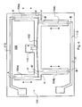
- an exemplary embodiment of one aspect of the invention will be described in the context of an optical signal attenuator indicated generally at 1, having a base part 8, three actuator beams 4a, 4b, 4c, each fixed at one end at a point A, B, C to the base part 8, and an actuator member 2, operably engaged with the other ends of the beams 4a, 4b, 4c at points A', B', C'.
- a shutter 10 is attached at the opposite end of the member 2.
- the shutter 10 In use, by movement of the member 2, the shutter 10 is brought into and out of the path of a free space light beam (not shown); the degree of attenuation is determined by the extent to which the shutter 10 cuts the beam.
- the movement of the member 2 is effected by differential expansion of the three beams 4a, 4b, 4c, that is to say, one beam 4a is caused to expand whilst the other two beams 4b, 4c are not.
- the two non-expanding beams 4b, 4c by virtue of their points of engagement B', C' to the member 2, in effect define a pivot point P.
- the point of engagement A' of the expanding beam 4a to the member 2 is the point at which the beam 4a acts upon member 2.
- the differential expansion results in the expanding beam 4a acting upon the member 2 thereby to produce a torque which effects pivoting of the member 2 about the pivot point P.
- the expanding beam 4a expands and contracts, whilst the two non-expanding beams 4b, 4c remain relatively stable, the member 2 see-saws about the pivot point P causing the shutter 10 to go up and down.
- the base part 8, beams 4 and member 2 are all micromachined out of highly doped silicon, such that the points of engagement A', B', C' of the beams 4 with the member 2 are actually continuous.
- Metal contacts 12 are applied to the expandable beam 4a so that a current may be induced to flow longitudinally along the beam 4a.
- the current results in resistive heating of the beam 4a causing it to expand longitudinally.
- the beam 4a is fixed at only one end to the base part 8, the beam is displaced longitudinally and it is this longitudinal expansion upon which the actuation of the member 2 depends.
- the beam 4a is displaced in the direction of expansion. This is in contrast to prior art arrangements where the beam displacement was substantially perpendicular to the direction of expansion.
- the degree of longitudinal expansion will depend upon its length, the resistance of the beam 4a, as partly dictated by its dimensions, and the current induced.
- FIG. 2 A further exemplary embodiment of this first, one aspect of the invention is shown in figures 2.
- This embodiment has two, rather than one, expandable beams 4a, the member 2 is parallel to, rather than perpendicular to, the beam 4, there is a virtual pivot point P and the current path between the contacts 12 is separated between the two beams, but the principle of operation is otherwise as described with reference to figure 1.
- the advantage of separating the current paths is that one of the contacts 12 does not need to extend along the full length of one of the beams 4a.
- an exemplary embodiment of another aspect of the invention will be described in the context of another optical signal attenuator indicated generally at 101, including a base part 108, two opposed actuator beams 104a, 104b each fixed at one end A, B respectively to the base part 108, and an actuator member 102 operably engages the other ends A', B' of the beams 104a, 104b.
- the member 102 and the beams 104a, 104b are micromachined from highly doped silicon, and, at the ends A', B', the beams 104a, 104b are in electrical contact with the member 102.
- a shutter 110 is attached. Two metal contacts 112a, 112b are applied to the base 108, one each opposite the beam ends A and B respectively.
- the beams 104a, 104b by virtue of their points of engagement with the member 102 in effect define a pivot point P.
- the movement of the member 102 is effected by the simultaneous expansion of the two beams 104a, 104b.
- the expansion of the two beams is caused by resistive heating of the two beams 104a, 104b as a result of current flowing between the contacts 112a and 112b as a result of the current path made by the beams 104a, 104b and the intervening part of the member 102.
- the simultaneous expansion results in the two beams 104a, 104b acting on the member 102 at the points of engagement A' and B' respectively thereby producing a torque about pivot point P.
- the member 102 see-saws about the pivot point P causing the shutter 110 to go up and down.
- the optical signal attenuator 101 illustrated in figure 4 has two sets of simultaneously acting beams 104, with each set acting at one end of the member 102 such that simultaneous expansion of all the beams 4 results in an arching of the member 102.
- the optical signal attenuator 101 illustrated in figure 5 is identical to the embodiment illustrated in figure 4 except that each beam 104 in each set is divided longitudinally into individual sub-beams.
- the selection of number and size of the beam 104 or sub-beams 104 is a matter of balancing the mechanical and heating characteristics of the beams 104.
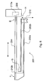
- yet another optical signal attenuator indicated generally at 201 including a base part 208, an actuator beam 204, fixed at one end E to the base part 208 and being generally L-shaped at the opposite end F, and one 202a of two actuator members 202a, 202b is operably engaged by the L-shaped end F of the beam 204.
- the second 202b of the two actuator members 202a, 202b which extends parallel to the first member 202a, is fixed at one end G, nearest to the L-shaped end F of the beam 204.
- the members 202a, 202b and the beam 204 are micromachined from highly doped silicon.
- a shutter 210 is attached.
- Two metal contacts 212a, 212b are applied to opposite ends E, F of the beam 204 respectively.
- differential movement of the members 202a, 202b effects movement of the shutter 210 into and out of a free space light beam (not shown); the degree of attenuation is determined by the extent to which the shutter 210 cuts the beam.
- Differential movement of the members 202a, 202b that is to say movement of one member 202a relative to the other member 202b, is effected by longitudinal expansion of the beam 204, brought about by passing a current between the two contacts 212a, 212b, which "pulls" or forces the beam 202a in the longitudinal direction, away from the shutter 210; because the second beam 202b is fixed at its end E and because the beams 202a, 202b are co-fixed at their remote ends H to the shutter 210, the puuling results in bending of the beams 202a, 202b, causing the shutter to move vertically.
- the advantages of this embodiment are: i) its actuation efficiency in terms expansion required per degree of movement of the shutter partly because of the physical separation of the beam and the members which enables the members to be kept relatively cool whilst the beam is being heated; ii) the compact nature of the beam/member arrangement allows the actuator to be arrayed in an attenuation device with relatively narrow spacing between attenuators thereby minimising space requirements.
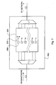
- any of the embodiments described with reference to figures 1 to 5 may be utilised in an optical attenuator 301, as an example of a MEMS device, at a node 302 in an optical communications network.
- the attenuator 301 may comprise a number of shutters 305, corresponding to the number of channels involved in the network, each operated by a separate MEMS actuator 308.
- the invention is directed to a MEMS actuator 1 comprising an actuator member 2 operably engaged by at least one actuator beam 4 and heating means 12 for heating the or each beam 4.
- the heating may cause expansion of the or each beam 4, wherein the or each beam 4 has two ends A, A' and the or each beam 4 is fixed at only one end A and wherein the expansion effects movement of the actuator member 2.
- the heating may cause thermal expansion of the beam 4 in one direction and longitudinal displacement of the beam 4 in the direction of thermal expansion, which longitudinal displacement effects movement of the actuator member 2.
- the beam 4 may act on the member 2 at a position in relation to a pivot point P so as to produce a torque which effects pivoting of the member 2 about the pivot point P.
- the actuator may have at least two actuator beams 4 and heating the at least two beams 4 may cause simultaneous expansion of the at least two beams 4, which simultaneous expansion effects movement of the actuator member 2. Alternatively, heating one of the at least two beams 4 may cause differential expansion of the at least two beams 4, which differential expansion effects movement of the actuator member 2.
- the actuator may have at least two actuator members 202 operably engaged by at least one actuator beam204 and heating the or each beam 204 may cause expansion of the or each beam 204, which expansion effects differential movement of the at least two members 202 or bending of the at least two members 202.
Landscapes
- Engineering & Computer Science (AREA)
- Chemical & Material Sciences (AREA)
- Computer Hardware Design (AREA)
- Microelectronics & Electronic Packaging (AREA)
- Combustion & Propulsion (AREA)
- Physics & Mathematics (AREA)
- Electromagnetism (AREA)
- Analytical Chemistry (AREA)
- Mechanical Engineering (AREA)
- General Engineering & Computer Science (AREA)
- Mechanical Light Control Or Optical Switches (AREA)
- Micromachines (AREA)
Applications Claiming Priority (2)
| Application Number | Priority Date | Filing Date | Title |
|---|---|---|---|
| US09/997,955 US20030101721A1 (en) | 2001-11-30 | 2001-11-30 | MEMS actuators |
| US997955 | 2001-11-30 |
Publications (1)
| Publication Number | Publication Date |
|---|---|
| EP1316977A2 true EP1316977A2 (fr) | 2003-06-04 |
Family
ID=25544598
Family Applications (1)
| Application Number | Title | Priority Date | Filing Date |
|---|---|---|---|
| EP02258280A Withdrawn EP1316977A2 (fr) | 2001-11-30 | 2002-11-29 | Actuateur micromécanique |
Country Status (3)
| Country | Link |
|---|---|
| US (1) | US20030101721A1 (fr) |
| EP (1) | EP1316977A2 (fr) |
| CA (1) | CA2413387A1 (fr) |
Cited By (6)
| Publication number | Priority date | Publication date | Assignee | Title |
|---|---|---|---|---|
| WO2007138266A1 (fr) * | 2006-05-25 | 2007-12-06 | University Of Durham | Dispositif d'actionneur électro-mécanique et appareil incorporant un tel dispositif |
| DE102008011175A1 (de) * | 2008-02-26 | 2009-09-03 | Nb Technologies Gmbh | Mikromechanischer Aktuator |
| FR2964653A1 (fr) * | 2010-09-13 | 2012-03-16 | Commissariat Energie Atomique | Dispositif resonant a actionnement dans le plan, et procede de fabrication du dispositif |
| EP2749890A1 (fr) * | 2012-12-27 | 2014-07-02 | Nederlandse Organisatie voor toegepast -natuurwetenschappelijk onderzoek TNO | Poutre composite avec une rigidité réglable |
| EP3159703A1 (fr) * | 2015-10-23 | 2017-04-26 | Vmicro | Dispositif et systeme microelectromecanique avec transducteur resistif a faible impedance |
| CN117052620A (zh) * | 2023-06-12 | 2023-11-14 | 中国科学院长春光学精密机械与物理研究所 | 基于热膨胀原理的差动式促动器 |
Families Citing this family (5)
| Publication number | Priority date | Publication date | Assignee | Title |
|---|---|---|---|---|
| US20070243073A1 (en) * | 2006-03-08 | 2007-10-18 | U.S.A. As Represented By The Administrator Of The National Aeronautics And Space Administration | Thermally Driven Piston Assembly And Position Control Therefor |
| WO2015153179A1 (fr) * | 2014-04-01 | 2015-10-08 | Agiltron, Inc. | Microstructure de déplacement électromécanique et procédé de commande de déplacement |
| JP6216485B1 (ja) * | 2016-03-23 | 2017-10-18 | 住友精密工業株式会社 | 変位拡大機構及びシャッタ装置 |
| US11409049B2 (en) * | 2017-03-17 | 2022-08-09 | Sumitomo Precision Products Co., Ltd. | MEMS element and optical apparatus using the same |
| US10962765B1 (en) | 2019-03-27 | 2021-03-30 | Agiltron, Inc. | Large motion latching microelectromechanical displacement structures |
Family Cites Families (2)
| Publication number | Priority date | Publication date | Assignee | Title |
|---|---|---|---|---|
| US5121089A (en) * | 1990-11-01 | 1992-06-09 | Hughes Aircraft Company | Micro-machined switch and method of fabrication |
| US6275325B1 (en) * | 2000-04-07 | 2001-08-14 | Microsoft Corporation | Thermally activated microelectromechanical systems actuator |
-
2001
- 2001-11-30 US US09/997,955 patent/US20030101721A1/en not_active Abandoned
-
2002
- 2002-11-29 EP EP02258280A patent/EP1316977A2/fr not_active Withdrawn
- 2002-11-29 CA CA002413387A patent/CA2413387A1/fr not_active Abandoned
Cited By (14)
| Publication number | Priority date | Publication date | Assignee | Title |
|---|---|---|---|---|
| US9165734B2 (en) | 2006-05-25 | 2015-10-20 | University Of Durham | Electro-mechanical actuator device and apparatus incorporating such device |
| GB2452176A (en) * | 2006-05-25 | 2009-02-25 | Univ Durham | Electro-mechanical actuator device and apparatus incorporating such device |
| WO2007138266A1 (fr) * | 2006-05-25 | 2007-12-06 | University Of Durham | Dispositif d'actionneur électro-mécanique et appareil incorporant un tel dispositif |
| DE102008011175A1 (de) * | 2008-02-26 | 2009-09-03 | Nb Technologies Gmbh | Mikromechanischer Aktuator |
| DE102008011175B4 (de) * | 2008-02-26 | 2010-05-12 | Nb Technologies Gmbh | Mikromechanischer Aktuator und Verfahren zu seiner Herstellung |
| US9293686B2 (en) | 2010-09-13 | 2016-03-22 | Commissariat a l'énergie atomique et aux énergies alternatives | In-plane actuated resonant device and method of manufacturing the device |
| WO2012034949A1 (fr) * | 2010-09-13 | 2012-03-22 | Commissariat à l'énergie atomique et aux énergies alternatives | Dispositif resonant a actionnement dans le plan, et procede de fabrication du dispositif |
| FR2964653A1 (fr) * | 2010-09-13 | 2012-03-16 | Commissariat Energie Atomique | Dispositif resonant a actionnement dans le plan, et procede de fabrication du dispositif |
| EP2749890A1 (fr) * | 2012-12-27 | 2014-07-02 | Nederlandse Organisatie voor toegepast -natuurwetenschappelijk onderzoek TNO | Poutre composite avec une rigidité réglable |
| WO2014104892A1 (fr) * | 2012-12-27 | 2014-07-03 | Nederlandse Organisatie Voor Toegepast-Natuurwetenschappelijk Onderzoek Tno | Système micromécanique ayant une poutre composite ayant une raideur apte à être réglée |
| EP3159703A1 (fr) * | 2015-10-23 | 2017-04-26 | Vmicro | Dispositif et systeme microelectromecanique avec transducteur resistif a faible impedance |
| FR3042905A1 (fr) * | 2015-10-23 | 2017-04-28 | Vmicro | Dispositif et systeme microelectromecanique avec transducteur resistif a faible impedance |
| US9815686B2 (en) | 2015-10-23 | 2017-11-14 | Vmicro | Microelectromechanical device and system with low-impedance resistive transducer |
| CN117052620A (zh) * | 2023-06-12 | 2023-11-14 | 中国科学院长春光学精密机械与物理研究所 | 基于热膨胀原理的差动式促动器 |
Also Published As
| Publication number | Publication date |
|---|---|
| US20030101721A1 (en) | 2003-06-05 |
| CA2413387A1 (fr) | 2003-05-30 |
Similar Documents
| Publication | Publication Date | Title |
|---|---|---|
| US6360539B1 (en) | Microelectromechanical actuators including driven arched beams for mechanical advantage | |
| EP1316977A2 (fr) | Actuateur micromécanique | |
| US6333583B1 (en) | Microelectromechanical systems including thermally actuated beams on heaters that move with the thermally actuated beams | |
| US6428173B1 (en) | Moveable microelectromechanical mirror structures and associated methods | |
| US6275325B1 (en) | Thermally activated microelectromechanical systems actuator | |
| US6218762B1 (en) | Multi-dimensional scalable displacement enabled microelectromechanical actuator structures and arrays | |
| US6327855B1 (en) | Actuators including serpentine arrangements of alternating actuating and opposing segments and related methods | |
| US6859580B2 (en) | Systems and methods for overcoming stiction using a lever | |
| US6657759B2 (en) | Bistable micromirror with contactless stops | |
| US6701037B2 (en) | MEMS-based noncontacting free-space optical switch | |
| US6137103A (en) | Opto-mechanical components | |
| CA2351992A1 (fr) | Actionneurs microelectromecaniques comprenant des structures de micro-poutre ondulees | |
| Tsai et al. | Design, fabrication, and characterization of a high fill-factor, large scan-angle, two-axis scanner array driven by a leverage mechanism | |
| US10752492B2 (en) | Microelectromechanical displacement structure and method for controlling displacement | |
| US6608714B2 (en) | Bi-directional, single material thermal actuator | |
| US20030161574A1 (en) | Planar lightwave wavelength device using moveable mirrors | |
| US8232858B1 (en) | Microelectromechanical (MEM) thermal actuator | |
| US7116855B2 (en) | Optical shuttle system and method used in an optical switch | |
| TW548232B (en) | MEMS-based wavelength equalizer | |
| US6983088B2 (en) | Thermal actuator and an optical waveguide switch including the same | |
| KR100789268B1 (ko) | 열 마이크로 구동기, 이에 직접 형성된 마이크로 미러, 열마이크로 구동기를 이용한 마이크로 미러 구동기구, 및이를 이용한 광 스위치 | |
| Katayama et al. | Micromachined curling optical switch array for PLC-based, integrated programmable add/drop multiplexer | |
| CN117891062A (zh) | Mems光开关及光交叉连接器 | |
| Zelinski | Design of Vertical-Lateral Thermal Actuators for MEMS | |
| Pandiyan et al. | Novel MEMS Electrothermal Actuators & Its Application |
Legal Events
| Date | Code | Title | Description |
|---|---|---|---|
| PUAI | Public reference made under article 153(3) epc to a published international application that has entered the european phase |
Free format text: ORIGINAL CODE: 0009012 |
|
| AK | Designated contracting states |
Designated state(s): AT BE BG CH CY CZ DE DK EE ES FI FR GB GR IE IT LI LU MC NL PT SE SK TR |
|
| AX | Request for extension of the european patent |
Extension state: AL LT LV MK RO SI |
|
| STAA | Information on the status of an ep patent application or granted ep patent |
Free format text: STATUS: THE APPLICATION HAS BEEN WITHDRAWN |
|
| 18W | Application withdrawn |
Effective date: 20040202 |