EP1316980A1 - Dispositif d'actionnement ou interrupteur pour un appareil miniature - Google Patents
Dispositif d'actionnement ou interrupteur pour un appareil miniature Download PDFInfo
- Publication number
- EP1316980A1 EP1316980A1 EP03003391A EP03003391A EP1316980A1 EP 1316980 A1 EP1316980 A1 EP 1316980A1 EP 03003391 A EP03003391 A EP 03003391A EP 03003391 A EP03003391 A EP 03003391A EP 1316980 A1 EP1316980 A1 EP 1316980A1
- Authority
- EP
- European Patent Office
- Prior art keywords
- membrane
- contacts
- switch
- contact
- electrically conductive
- Prior art date
- Legal status (The legal status is an assumption and is not a legal conclusion. Google has not performed a legal analysis and makes no representation as to the accuracy of the status listed.)
- Withdrawn
Links
- 239000012528 membrane Substances 0.000 claims abstract description 41
- 229920001940 conductive polymer Polymers 0.000 claims abstract description 10
- 229920000642 polymer Polymers 0.000 claims abstract description 9
- 239000004642 Polyimide Substances 0.000 claims abstract description 4
- 229920001721 polyimide Polymers 0.000 claims abstract description 4
- 239000004020 conductor Substances 0.000 claims description 20
- 239000000853 adhesive Substances 0.000 claims description 16
- 230000001070 adhesive effect Effects 0.000 claims description 16
- 239000000463 material Substances 0.000 claims description 10
- 239000000758 substrate Substances 0.000 claims description 7
- PXHVJJICTQNCMI-UHFFFAOYSA-N Nickel Chemical compound [Ni] PXHVJJICTQNCMI-UHFFFAOYSA-N 0.000 claims description 6
- 239000011231 conductive filler Substances 0.000 claims description 6
- 239000000945 filler Substances 0.000 claims description 3
- 239000002184 metal Substances 0.000 claims description 3
- 229910052751 metal Inorganic materials 0.000 claims description 3
- 229910052759 nickel Inorganic materials 0.000 claims description 3
- 238000005260 corrosion Methods 0.000 claims description 2
- 230000007797 corrosion Effects 0.000 claims description 2
- 239000003822 epoxy resin Substances 0.000 claims description 2
- PCHJSUWPFVWCPO-UHFFFAOYSA-N gold Chemical compound [Au] PCHJSUWPFVWCPO-UHFFFAOYSA-N 0.000 claims description 2
- 229910052737 gold Inorganic materials 0.000 claims description 2
- 239000010931 gold Substances 0.000 claims description 2
- 229920000647 polyepoxide Polymers 0.000 claims description 2
- 229920001225 polyester resin Polymers 0.000 claims description 2
- 239000004645 polyester resin Substances 0.000 claims description 2
- 229920005749 polyurethane resin Polymers 0.000 claims description 2
- 230000001105 regulatory effect Effects 0.000 claims description 2
- 229920002050 silicone resin Polymers 0.000 claims description 2
- BQCADISMDOOEFD-UHFFFAOYSA-N Silver Chemical compound [Ag] BQCADISMDOOEFD-UHFFFAOYSA-N 0.000 claims 1
- 238000005452 bending Methods 0.000 claims 1
- 239000006229 carbon black Substances 0.000 claims 1
- 229910001092 metal group alloy Inorganic materials 0.000 claims 1
- 229920013730 reactive polymer Polymers 0.000 claims 1
- 229910052709 silver Inorganic materials 0.000 claims 1
- 239000004332 silver Substances 0.000 claims 1
- 239000002322 conducting polymer Substances 0.000 abstract 3
- 239000007788 liquid Substances 0.000 description 7
- 229920001296 polysiloxane Polymers 0.000 description 7
- 238000000034 method Methods 0.000 description 4
- 230000000149 penetrating effect Effects 0.000 description 4
- 238000013461 design Methods 0.000 description 3
- 238000007789 sealing Methods 0.000 description 3
- -1 Nickel Chemical class 0.000 description 2
- 238000013459 approach Methods 0.000 description 2
- 239000011248 coating agent Substances 0.000 description 2
- 238000000576 coating method Methods 0.000 description 2
- 230000006870 function Effects 0.000 description 2
- 238000004519 manufacturing process Methods 0.000 description 2
- 230000002093 peripheral effect Effects 0.000 description 2
- 238000003825 pressing Methods 0.000 description 2
- 239000000126 substance Substances 0.000 description 2
- 230000000475 sunscreen effect Effects 0.000 description 2
- 239000000516 sunscreening agent Substances 0.000 description 2
- OKTJSMMVPCPJKN-UHFFFAOYSA-N Carbon Chemical compound [C] OKTJSMMVPCPJKN-UHFFFAOYSA-N 0.000 description 1
- 240000005702 Galium aparine Species 0.000 description 1
- 229910045601 alloy Inorganic materials 0.000 description 1
- 239000000956 alloy Substances 0.000 description 1
- 239000000919 ceramic Substances 0.000 description 1
- 238000010276 construction Methods 0.000 description 1
- 230000001419 dependent effect Effects 0.000 description 1
- 230000000694 effects Effects 0.000 description 1
- 229920001971 elastomer Polymers 0.000 description 1
- 238000005516 engineering process Methods 0.000 description 1
- 229920005570 flexible polymer Polymers 0.000 description 1
- 239000011521 glass Substances 0.000 description 1
- 239000010439 graphite Substances 0.000 description 1
- 229910002804 graphite Inorganic materials 0.000 description 1
- LNEPOXFFQSENCJ-UHFFFAOYSA-N haloperidol Chemical compound C1CC(O)(C=2C=CC(Cl)=CC=2)CCN1CCCC(=O)C1=CC=C(F)C=C1 LNEPOXFFQSENCJ-UHFFFAOYSA-N 0.000 description 1
- 238000009434 installation Methods 0.000 description 1
- 238000009413 insulation Methods 0.000 description 1
- 238000012423 maintenance Methods 0.000 description 1
- 150000002739 metals Chemical class 0.000 description 1
- 238000000465 moulding Methods 0.000 description 1
- 239000002884 skin cream Substances 0.000 description 1
- 239000004071 soot Substances 0.000 description 1
- 210000004243 sweat Anatomy 0.000 description 1
- 230000008961 swelling Effects 0.000 description 1
- 238000012546 transfer Methods 0.000 description 1
Images


Classifications
-
- H—ELECTRICITY
- H01—ELECTRIC ELEMENTS
- H01H—ELECTRIC SWITCHES; RELAYS; SELECTORS; EMERGENCY PROTECTIVE DEVICES
- H01H13/00—Switches having rectilinearly-movable operating part or parts adapted for pushing or pulling in one direction only, e.g. push-button switch
- H01H13/70—Switches having rectilinearly-movable operating part or parts adapted for pushing or pulling in one direction only, e.g. push-button switch having a plurality of operating members associated with different sets of contacts, e.g. keyboard
- H01H13/78—Switches having rectilinearly-movable operating part or parts adapted for pushing or pulling in one direction only, e.g. push-button switch having a plurality of operating members associated with different sets of contacts, e.g. keyboard characterised by the contacts or the contact sites
- H01H13/785—Switches having rectilinearly-movable operating part or parts adapted for pushing or pulling in one direction only, e.g. push-button switch having a plurality of operating members associated with different sets of contacts, e.g. keyboard characterised by the contacts or the contact sites characterised by the material of the contacts, e.g. conductive polymers
-
- H—ELECTRICITY
- H01—ELECTRIC ELEMENTS
- H01H—ELECTRIC SWITCHES; RELAYS; SELECTORS; EMERGENCY PROTECTIVE DEVICES
- H01H13/00—Switches having rectilinearly-movable operating part or parts adapted for pushing or pulling in one direction only, e.g. push-button switch
- H01H13/70—Switches having rectilinearly-movable operating part or parts adapted for pushing or pulling in one direction only, e.g. push-button switch having a plurality of operating members associated with different sets of contacts, e.g. keyboard
- H01H13/702—Switches having rectilinearly-movable operating part or parts adapted for pushing or pulling in one direction only, e.g. push-button switch having a plurality of operating members associated with different sets of contacts, e.g. keyboard with contacts carried by or formed from layers in a multilayer structure, e.g. membrane switches
-
- H—ELECTRICITY
- H01—ELECTRIC ELEMENTS
- H01H—ELECTRIC SWITCHES; RELAYS; SELECTORS; EMERGENCY PROTECTIVE DEVICES
- H01H2201/00—Contacts
- H01H2201/022—Material
- H01H2201/03—Composite
-
- H—ELECTRICITY
- H01—ELECTRIC ELEMENTS
- H01H—ELECTRIC SWITCHES; RELAYS; SELECTORS; EMERGENCY PROTECTIVE DEVICES
- H01H2207/00—Connections
- H01H2207/008—Adhesive means; Conductive adhesive
-
- H—ELECTRICITY
- H01—ELECTRIC ELEMENTS
- H01H—ELECTRIC SWITCHES; RELAYS; SELECTORS; EMERGENCY PROTECTIVE DEVICES
- H01H2217/00—Facilitation of operation; Human engineering
- H01H2217/002—Facilitation of operation; Human engineering actuable from both sides
-
- H—ELECTRICITY
- H01—ELECTRIC ELEMENTS
- H01H—ELECTRIC SWITCHES; RELAYS; SELECTORS; EMERGENCY PROTECTIVE DEVICES
- H01H2223/00—Casings
- H01H2223/002—Casings sealed
- H01H2223/003—Membrane embracing all keys
Definitions
- the present invention relates to an actuator, especially for electrical and electronic Small devices according to the preamble of claim 1, and a use of the device and a hearing aid with a Contraption.
- toggle switches For small electronics devices, such as Hearing aids are so-called “toggle switches” and others Switches used to e.g. between different Programs to adjust the volume or just to turn the device on or off.
- toggle switch there is usually one the contact switch covering flexible membrane, such as for example a molded silicone part, provided with a specially applied conductive layer.
- the function this silicone membrane molded part consists on the one hand in the Sealing the housing against ingress of moisture and on the other hand to trigger the switching functions.
- This Technology is similar to that of very simple safety mats Rubber or silicone, such as arranged at cheap calculators.
- the advantage of this technique is that it is very easy to set up and use. New is only that the silicone molding is a conductive layer having.
- the object of the present invention is thus in creating a switch or potentiometer or in an actuator in which the Switch contacts against the ingress of moisture and others Liquids are protected against pollution, and which contacts can be switched in the simplest way are.
- the object is achieved by means of a Actuating device according to the wording of claim 1 solved.
- An actuating device or a Switches for small electrical and electronic devices having at least two switching contacts, which via a spanning at least one of the contacts Membrane print on the membrane can be connected to each other are to trigger a switching process.
- At least one of the contacts is in a peripheral zone Arranged membrane, and with this via an electrical conductive polymer connected to a conductor track, and the other contact is spanned by the membrane in such a way that when the device or membrane is not actuated this or the conductor track spaced from the other contact is. When actuated or when pressure is on the membrane these can be deflected against the other contact in such a way that the trace touches the other contact.
- the membrane spanning the other contact is preferably designed so resilient that at Not actuating the membrane or the other contact facing conductor track are spaced from this.
- the conductive polymer is preferably an anisotropically electrically conductive adhesive, the Conductivity preferably due to the use of a corresponding filler is achieved in the polymer.
- the device according to the invention is on all sides against, for example, penetrating moisture
- an appropriate polymeric material such as for example the electrically conductive adhesive sealed the switch housing underneath.
- the proposed switch or the Actuators are particularly suitable for small electronic or electrical devices, such as especially for hearing aids.
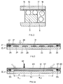
- FIGS 1a and 1b show a so-called “toggle switch” for the actuation of switch contacts in an electronic Smallest device 1 with connections 9 and 11, such as suitable for installation in a hearing aid.
- Switch contacts 5 In one Side area 6 of the switch housing 1 are on the one hand Switch contacts 5 arranged and a center Switch contact 7, which for triggering a Switching process are to be connected to each other.
- the Switch contacts 5 and 7 are covering or spanning a membrane or a so-called “cover layer” 13 provided, at the lower, facing the contacts Surface, a conductor track 15 is arranged.
- cover layer 13 To now the to connect lateral contacts 5 to the conductor track 15, is the cover layer 13 over an electrically conductive polymer 17 connected together.
- electrically conductive adhesive can be electrically conductive, for example Epoxy resins, polyurethane resins, silicone resins, Trade polyester resins, etc., the corresponding Polymer with electrically conductive fillers, such as metallic fillers, graphite, soot and the like are. Suitable as so-called cover layers are limited elastically flexible polymers such as polyimide.
- a so-called toggle pin 19 are used by means which the membrane or the cover layer 13 against the middle contact 7 is pressed until the conductor 15 with the contact 7 comes into contact.
- FIG. 1b shows the switch housing 1 and the cover layer 13 shown in top view. If it’s the Membrane or the cover layer 13 around a transparent membrane acts, the central electrode 7 is visible. Laterally and is hermetically sealed from the switch housing 1 the cover layer by means of the above-mentioned electrical conductive adhesive.
- a special Layer structure can have optimal To achieve contact properties.
- Contacts for relays preferably coated with gold, while in other applications other metals like Nickel, etc. can be used or special Alloys to prevent corrosion, for example.
- Figure 2 shows a section of Figure 1a in Enlargement, which is now clearly on the Lateral electrode 5 arranged on the side surface 6 it can be seen which of the electrically conductive Adhesive 17 with the conductor track 15 of the cover layer 13 connected is. In the sense of a schematic representation are the electrically conductive fillers as balls 18 shown.
- a further embodiment variant is in section in FIG of a switch 21 according to the invention, wherein it a position-sensitive or pressure sensitive switch or sensor.
- peripheral electrodes 25 via an electrically conductive Adhesive 41 containing electrically conductive fillers 43 connected to a cover layer 37, on the underside thereof a conductor track 39 is arranged.
- Adhesive 41 containing electrically conductive fillers 43 connected to a cover layer 37, on the underside thereof a conductor track 39 is arranged.
- Various electrodes 27 to 35 are arranged position sensitive or pressure sensitive switches, as in Figure 3 shown, depending on the location or Actuating force a specific signal can be read out. With this signal e.g. in a hearing aid Program selection or volume can be regulated.
- the cover layer can also affect the pressure by means of which only one electrode is contacted or several electrodes simultaneously through the conductor track be touched. In addition, by moving the Attack the actuation site or only one electrode be contacted.
- the switch shown in Figure 3 can also with a "Snap frog" -like principle can be realized.
- a Another option is to switch according to Figure 3 with a partially flexible housing or on a flexible substrate 23 as a so-called “magic switch” train.
- FIGS. 4a and 4b again show a further embodiment of a switch 51 according to the invention, in which lateral electrodes 55 are again connected to the cover layer 61 via an adhesive 65 provided with electrically conductive fillers 67, on the underside of which the conductor track 63 is again arranged.
- a single, longitudinally extended, central electrode 57 is formed, which can be actuated, for example, according to the "click frog" principle, FIG. 4a showing the switch in longitudinal section and FIG. 4b the switch in a view from above without a cover layer.
- the carrier substrate 53 should be made of a somewhat thicker material than the switching electrode 57.
- the actuation location 60 can be measured differentially according to the correlation x: y ⁇ E x : E y , as shown schematically in FIG. 4a.
- FIG Design variant of a switch according to the invention shown Another schematic is shown in section in FIG Design variant of a switch according to the invention shown.
- the switch arranged on a substrate 73 71 again has electrical conductors on each side or Electrodes 75, which by means of an insulation layer 74 are shielded from the outside. Again, these are Electrodes 75 with an electrically conductive adhesive 77 a so-called cover layer 83 connected to his Underside of a conductor track 81. By Pressing down this cover layer 83 becomes the conductor track 81 to the electrode 85 arranged centrally in the switch 71 pressed, making contact between the outer Electrodes 75 and the central electrode 85 are produced is and thus a transmitted signal by the with the central conductor connected conductor 87 continued can be. 5 are also shown in the switch all conductor tracks, for example, against The effects of moisture from the outside are hermetically sealed or protected against penetrating liquids.
- Switch shown can have existing problems today the so-called “toggle switches” sustainably solved or be eliminated. This is particularly the case with hearing aids, where the Use of the so-called “toggle switches” to the input known problems described.
- switches can other embodiments, of course be designed according to the invention, or else Switches or controllers can be used with the described Actuators to be replaced. Everywhere, where Moisture, any chemical substances, sweat, Sunscreen, etc. when operating switches one Role play, the proposed according to the invention Switches a reliable approach. So you can reliable even under unfavorable conditions, working, small electronic devices with appropriate switches are provided. For the Production of such devices, the invention means a strong cheapening and an increase in reliability, by cheap and well known materials and Molded parts can be used. Maintenance of the Small electronic devices can be significantly reduced become.
Landscapes
- Push-Button Switches (AREA)
Priority Applications (1)
| Application Number | Priority Date | Filing Date | Title |
|---|---|---|---|
| EP03003391A EP1316980A1 (fr) | 2003-02-14 | 2003-02-14 | Dispositif d'actionnement ou interrupteur pour un appareil miniature |
Applications Claiming Priority (1)
| Application Number | Priority Date | Filing Date | Title |
|---|---|---|---|
| EP03003391A EP1316980A1 (fr) | 2003-02-14 | 2003-02-14 | Dispositif d'actionnement ou interrupteur pour un appareil miniature |
Publications (1)
| Publication Number | Publication Date |
|---|---|
| EP1316980A1 true EP1316980A1 (fr) | 2003-06-04 |
Family
ID=8185867
Family Applications (1)
| Application Number | Title | Priority Date | Filing Date |
|---|---|---|---|
| EP03003391A Withdrawn EP1316980A1 (fr) | 2003-02-14 | 2003-02-14 | Dispositif d'actionnement ou interrupteur pour un appareil miniature |
Country Status (1)
| Country | Link |
|---|---|
| EP (1) | EP1316980A1 (fr) |
Citations (5)
| Publication number | Priority date | Publication date | Assignee | Title |
|---|---|---|---|---|
| US3909564A (en) * | 1974-08-08 | 1975-09-30 | Amp Inc | Keyboard assembly with foldable printed circuit matrix switch array, and key actuator locking slide plate |
| US4433223A (en) * | 1981-08-24 | 1984-02-21 | Oak Industries Inc. | Pressure-sensitive adhesive and application thereof |
| US5228562A (en) * | 1991-09-09 | 1993-07-20 | Gm Nameplate, Inc. | Membrane switch and fabrication method |
| US5463692A (en) * | 1994-07-11 | 1995-10-31 | Resistance Technology Inc. | Sandwich switch construction for a hearing aid |
| EP0936645A2 (fr) * | 1998-02-10 | 1999-08-18 | BSH Bosch und Siemens Hausgeräte GmbH | Dispositif avec au moins un commutateur-capteur |
-
2003
- 2003-02-14 EP EP03003391A patent/EP1316980A1/fr not_active Withdrawn
Patent Citations (5)
| Publication number | Priority date | Publication date | Assignee | Title |
|---|---|---|---|---|
| US3909564A (en) * | 1974-08-08 | 1975-09-30 | Amp Inc | Keyboard assembly with foldable printed circuit matrix switch array, and key actuator locking slide plate |
| US4433223A (en) * | 1981-08-24 | 1984-02-21 | Oak Industries Inc. | Pressure-sensitive adhesive and application thereof |
| US5228562A (en) * | 1991-09-09 | 1993-07-20 | Gm Nameplate, Inc. | Membrane switch and fabrication method |
| US5463692A (en) * | 1994-07-11 | 1995-10-31 | Resistance Technology Inc. | Sandwich switch construction for a hearing aid |
| EP0936645A2 (fr) * | 1998-02-10 | 1999-08-18 | BSH Bosch und Siemens Hausgeräte GmbH | Dispositif avec au moins un commutateur-capteur |
Similar Documents
| Publication | Publication Date | Title |
|---|---|---|
| EP2452435B1 (fr) | Touche à effleurement à reconnaissance capacitive de la touche | |
| EP0548379B1 (fr) | Prothèse auditive | |
| DE19526254C2 (de) | Passiver magnetischer Positionssensor | |
| EP0451676A2 (fr) | Clavier pour un appareil électronique de divertissement | |
| DE3226348A1 (de) | Tastaturschalteinheit | |
| EP2225540B1 (fr) | Carte de circuits imprimés pour indicateur de niveau de remplissage d'un réservoir de véhicule | |
| DE3619035C2 (fr) | ||
| WO2006119657A1 (fr) | Contact electroconducteur et procede de fabrication | |
| DE3643124C2 (fr) | ||
| EP1695035A2 (fr) | Dispositif de commande | |
| EP1316980A1 (fr) | Dispositif d'actionnement ou interrupteur pour un appareil miniature | |
| WO2001008182A1 (fr) | Commutateur a effleurement pour cartes a puce | |
| EP2081197B1 (fr) | Dispositif de détermination de l'emplacement d'un point de compression | |
| DE10326141B4 (de) | Elektromechanische Baugruppe | |
| DE102008014463B4 (de) | Bedieneinheit für eine Fahrzeugkomponente, insbesondere für eine Belüftungs- und/oder Klimaanlage eines Fahrzeuges | |
| EP1463376B1 (fr) | Elément de commande pour des appareils auditifs et des prothèses auditives | |
| DE19700846C1 (de) | Elektrische Schaltvorrichtung | |
| DE10040151C1 (de) | Tastatur zum sicheren Auslösen von elektrischen Schaltfunktionen | |
| EP1318535A1 (fr) | Touche à membrane pliable et méthode de production | |
| DE3337122C2 (fr) | ||
| DE2246714A1 (de) | Schalttaste mit einer schnappmechanik | |
| DE3728166C2 (fr) | ||
| EP1215696B1 (fr) | Ensemble d'un clavier à touches pour un dispositif électrique | |
| EP1819895A1 (fr) | Module electromecanique | |
| DE102004004136B4 (de) | Elektrisches Kleingerät mit einer Schalteinrichtung |
Legal Events
| Date | Code | Title | Description |
|---|---|---|---|
| PUAI | Public reference made under article 153(3) epc to a published international application that has entered the european phase |
Free format text: ORIGINAL CODE: 0009012 |
|
| AK | Designated contracting states |
Designated state(s): AT BE BG CH CY CZ DE DK EE ES FI FR GB GR HU IE IT LI LU MC NL PT SE SI SK TR |
|
| AX | Request for extension of the european patent |
Extension state: AL LT LV MK RO |
|
| AKX | Designation fees paid | ||
| REG | Reference to a national code |
Ref country code: DE Ref legal event code: 8566 |
|
| STAA | Information on the status of an ep patent application or granted ep patent |
Free format text: STATUS: THE APPLICATION IS DEEMED TO BE WITHDRAWN |
|
| 18D | Application deemed to be withdrawn |
Effective date: 20031205 |