EP1317033A2 - Amplificateur d'un faisceau laser par pompage d'un matériau non linéaire et dispositif d'émission laser comportant un tel amplificateur - Google Patents
Amplificateur d'un faisceau laser par pompage d'un matériau non linéaire et dispositif d'émission laser comportant un tel amplificateur Download PDFInfo
- Publication number
- EP1317033A2 EP1317033A2 EP02292453A EP02292453A EP1317033A2 EP 1317033 A2 EP1317033 A2 EP 1317033A2 EP 02292453 A EP02292453 A EP 02292453A EP 02292453 A EP02292453 A EP 02292453A EP 1317033 A2 EP1317033 A2 EP 1317033A2
- Authority
- EP
- European Patent Office
- Prior art keywords
- light
- optical structure
- active
- pumping
- pumping diodes
- Prior art date
- Legal status (The legal status is an assumption and is not a legal conclusion. Google has not performed a legal analysis and makes no representation as to the accuracy of the status listed.)
- Granted
Links
Images


Classifications
-
- H—ELECTRICITY
- H01—ELECTRIC ELEMENTS
- H01S—DEVICES USING THE PROCESS OF LIGHT AMPLIFICATION BY STIMULATED EMISSION OF RADIATION [LASER] TO AMPLIFY OR GENERATE LIGHT; DEVICES USING STIMULATED EMISSION OF ELECTROMAGNETIC RADIATION IN WAVE RANGES OTHER THAN OPTICAL
- H01S3/00—Lasers, i.e. devices using stimulated emission of electromagnetic radiation in the infrared, visible or ultraviolet wave range
- H01S3/09—Processes or apparatus for excitation, e.g. pumping
- H01S3/091—Processes or apparatus for excitation, e.g. pumping using optical pumping
- H01S3/094—Processes or apparatus for excitation, e.g. pumping using optical pumping by coherent light
- H01S3/0941—Processes or apparatus for excitation, e.g. pumping using optical pumping by coherent light of a laser diode
-
- H—ELECTRICITY
- H01—ELECTRIC ELEMENTS
- H01S—DEVICES USING THE PROCESS OF LIGHT AMPLIFICATION BY STIMULATED EMISSION OF RADIATION [LASER] TO AMPLIFY OR GENERATE LIGHT; DEVICES USING STIMULATED EMISSION OF ELECTROMAGNETIC RADIATION IN WAVE RANGES OTHER THAN OPTICAL
- H01S3/00—Lasers, i.e. devices using stimulated emission of electromagnetic radiation in the infrared, visible or ultraviolet wave range
- H01S3/02—Constructional details
- H01S3/04—Arrangements for thermal management
- H01S3/042—Arrangements for thermal management for solid state lasers
-
- H—ELECTRICITY
- H01—ELECTRIC ELEMENTS
- H01S—DEVICES USING THE PROCESS OF LIGHT AMPLIFICATION BY STIMULATED EMISSION OF RADIATION [LASER] TO AMPLIFY OR GENERATE LIGHT; DEVICES USING STIMULATED EMISSION OF ELECTROMAGNETIC RADIATION IN WAVE RANGES OTHER THAN OPTICAL
- H01S3/00—Lasers, i.e. devices using stimulated emission of electromagnetic radiation in the infrared, visible or ultraviolet wave range
- H01S3/05—Construction or shape of optical resonators; Accommodation of active medium therein; Shape of active medium
- H01S3/06—Construction or shape of active medium
- H01S3/0602—Crystal lasers or glass lasers
- H01S3/0604—Crystal lasers or glass lasers in the form of a plate or disc
-
- H—ELECTRICITY
- H01—ELECTRIC ELEMENTS
- H01S—DEVICES USING THE PROCESS OF LIGHT AMPLIFICATION BY STIMULATED EMISSION OF RADIATION [LASER] TO AMPLIFY OR GENERATE LIGHT; DEVICES USING STIMULATED EMISSION OF ELECTROMAGNETIC RADIATION IN WAVE RANGES OTHER THAN OPTICAL
- H01S3/00—Lasers, i.e. devices using stimulated emission of electromagnetic radiation in the infrared, visible or ultraviolet wave range
- H01S3/05—Construction or shape of optical resonators; Accommodation of active medium therein; Shape of active medium
- H01S3/06—Construction or shape of active medium
- H01S3/0602—Crystal lasers or glass lasers
- H01S3/0612—Non-homogeneous structure
-
- H—ELECTRICITY
- H01—ELECTRIC ELEMENTS
- H01S—DEVICES USING THE PROCESS OF LIGHT AMPLIFICATION BY STIMULATED EMISSION OF RADIATION [LASER] TO AMPLIFY OR GENERATE LIGHT; DEVICES USING STIMULATED EMISSION OF ELECTROMAGNETIC RADIATION IN WAVE RANGES OTHER THAN OPTICAL
- H01S3/00—Lasers, i.e. devices using stimulated emission of electromagnetic radiation in the infrared, visible or ultraviolet wave range
- H01S3/09—Processes or apparatus for excitation, e.g. pumping
- H01S3/091—Processes or apparatus for excitation, e.g. pumping using optical pumping
- H01S3/094—Processes or apparatus for excitation, e.g. pumping using optical pumping by coherent light
- H01S3/09408—Pump redundancy
-
- H—ELECTRICITY
- H01—ELECTRIC ELEMENTS
- H01S—DEVICES USING THE PROCESS OF LIGHT AMPLIFICATION BY STIMULATED EMISSION OF RADIATION [LASER] TO AMPLIFY OR GENERATE LIGHT; DEVICES USING STIMULATED EMISSION OF ELECTROMAGNETIC RADIATION IN WAVE RANGES OTHER THAN OPTICAL
- H01S3/00—Lasers, i.e. devices using stimulated emission of electromagnetic radiation in the infrared, visible or ultraviolet wave range
- H01S3/09—Processes or apparatus for excitation, e.g. pumping
- H01S3/091—Processes or apparatus for excitation, e.g. pumping using optical pumping
- H01S3/094—Processes or apparatus for excitation, e.g. pumping using optical pumping by coherent light
- H01S3/094084—Processes or apparatus for excitation, e.g. pumping using optical pumping by coherent light with pump light recycling, i.e. with reinjection of the unused pump light, e.g. by reflectors or circulators
-
- H—ELECTRICITY
- H01—ELECTRIC ELEMENTS
- H01S—DEVICES USING THE PROCESS OF LIGHT AMPLIFICATION BY STIMULATED EMISSION OF RADIATION [LASER] TO AMPLIFY OR GENERATE LIGHT; DEVICES USING STIMULATED EMISSION OF ELECTROMAGNETIC RADIATION IN WAVE RANGES OTHER THAN OPTICAL
- H01S3/00—Lasers, i.e. devices using stimulated emission of electromagnetic radiation in the infrared, visible or ultraviolet wave range
- H01S3/09—Processes or apparatus for excitation, e.g. pumping
- H01S3/091—Processes or apparatus for excitation, e.g. pumping using optical pumping
- H01S3/094—Processes or apparatus for excitation, e.g. pumping using optical pumping by coherent light
- H01S3/0941—Processes or apparatus for excitation, e.g. pumping using optical pumping by coherent light of a laser diode
- H01S3/09415—Processes or apparatus for excitation, e.g. pumping using optical pumping by coherent light of a laser diode the pumping beam being parallel to the lasing mode of the pumped medium, e.g. end-pumping
-
- H—ELECTRICITY
- H01—ELECTRIC ELEMENTS
- H01S—DEVICES USING THE PROCESS OF LIGHT AMPLIFICATION BY STIMULATED EMISSION OF RADIATION [LASER] TO AMPLIFY OR GENERATE LIGHT; DEVICES USING STIMULATED EMISSION OF ELECTROMAGNETIC RADIATION IN WAVE RANGES OTHER THAN OPTICAL
- H01S3/00—Lasers, i.e. devices using stimulated emission of electromagnetic radiation in the infrared, visible or ultraviolet wave range
- H01S3/23—Arrangements of two or more lasers not provided for in groups H01S3/02 - H01S3/22, e.g. tandem arrangements of separate active media
- H01S3/2308—Amplifier arrangements, e.g. MOPA
- H01S3/2316—Cascaded amplifiers
Definitions
- the invention relates to a device for amplifying a beam. laser by pumping a non-linear material.
- the laser amplification and emission devices offered by the invention particularly advantageously find application in areas where medium or high energy emissions are desired, especially in the military for the implementation of countermeasures optical, or for the realization of primary sources in lithography EUV, or the creation of laser treatment tools requiring high energies (application to shot blasting, etc.).
- Non-linear active ingredients allow good efficiency for active media various Nd, Yag, Yb: Yag or others. Powers on the order of multi kilowatt can be obtained for almost 3 levels lasers like Yb: YAG.
- the invention has the advantage of allowing emissions of medium or high energy.
- an amplifier laser type beam comprising an element of active material not linear, as well as pumping diodes and an optical structure capable of guide by successive reflections the light emitted by said diodes of pumping to the active element.
- a lens element is provided.
- guide which is superimposed on the nonlinear active material element and the light emitted by the pumping diodes is guided to the active element by successive reflections in the thickness of said lens element guide by being injected into it at its periphery.
- the diodes are distributed at the periphery of the guide lens element.
- the light emitted by the diodes is guided to the element forming the guide lens by fiber optic means.
- the active element and the optical structure are arranged on a heat sink element, this which also helps to allow strong amplification powers.
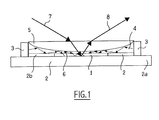
- the amplification device shown in the figures has a element 1 of non-linear active material sandwiched between a well thermal 2 which ensures its cooling and a disc 4 which presents itself in the form of a transparent optical lens at the wavelength of pumping, as well as the wavelength (s) of the laser beam amplified.
- a plurality of pumping diodes 3 are distributed over the disc circumference 4.
- optical fibers between the diodes 3 and the periphery of the disc 4, said fibers being intended to guide the light emitted by the diodes 3 to the periphery disc 4.
- Element 1 of active material is a thin disc which has a diameter of a few centimeters, and a thickness of a few tenths of millimeters.
- the heat sink 2 is in the form of a metal plate 2a which carries an annular collar 2b likewise thickness as disc 1 and internal diameter corresponding to external diameter of said disc.
- the transparent disc 4 has at its face opposite the disc 1 and at well 2 a concave shape.
- This disc 5 is shaped complementary to that of said disc 4, so that the assembly constituted by the disc 4 and the disc 5 together constitutes a blade with faces parallel.
- the disc 1 receives a laser beam 7 to be amplified which comes from a laser source not shown and which crosses the disc 5 and the disc 4.
- This beam 7 passes through said disc 1 in its thickness to reflect on its face opposite to the disc 4 and cross the said again disc 1, the beam leaving the disc then being an amplified beam 8.
- the disc 1 is advantageously metallized at its face opposite the disc 4.
- Metallization is also advantageously provided on the face of the disc 4 which is directly in look of the element 2 forming a heat sink.
- the pumping carried out by the diodes 3 on the disk 1 transfers a large part of the energy emitted by said diodes 3 to amplify the laser beam 8 which is obtained at the output.
- the two elements 4 and 5 together constitute a optical arrangement which guides the light emitted from the diodes 3 to concentrate it on the disc 1 of non-linear material.
- These two glass layers 4 and 5 indeed form between them a glass / glass diopter, the beams emitted by the diodes 3 reflecting at the interface 4/5.
- the pumping beams emitted at the level of the periphery of the disc 4 propagate in the lower layer 4 and are concentrated in thickness towards the center of the device, i.e. on disc 1.
- the glass disc 4 may for example have a diameter typically between 20 and 30 cm.
- the diodes distributed around its circumference can typically be at number of one hundred each emitting a power of the order of 1 Joule at 100 Hz.
- a reflective layer is placed between the disc 1 and the cooler block 2 for optimal reflection of the light from pumping and the laser beam to be amplified.
- a reflective layer is also advantageously placed between the glass disc formed by layers 4 and 5 and the rest of the block cooler 2.
- Such reflective layers are for example applied by metallic deposit.
- the reflective layer is preferably deposited in this case on the glass part.
- the disc 1 is pumpable by about 5 Joules; which is compatible with a disc with a surface between 10 and 100 cm2 depending on the material.
- the circular shape of the edge disc device 4b produces a lens effect tending to concentrate the beams emitted towards the center of the glass pellet 4/5.
- the thickness of the disc 4 at its peripheral edge being chosen at least equal to the height of each diode 3, such focus lenses are also not necessary for a thickness concentration.
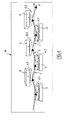
- a series of such unit amplifiers is adopted in accordance with that of FIG. 1, placed in staggered rows, that is to say one after the other along a main X-axis path.
- the assembly presents a configuration of oscillator type, based on use at one end of a reflector 16 followed by a “Q switch” 18 and, at another end, by a coupler 17 forming the output of the device.
- a reflector 16 followed by a “Q switch” 18 and, at another end, by a coupler 17 forming the output of the device.
- two cooling referenced 2 each consisting of the same block cooler brought into contact with all unit amplifiers present on the same side of the main axis X of the laser beam.
- FIG. 6 an optical amplifier assembly has been shown. for oscillator, in which the input of the device is formed by a oscillator 15, the output being constituted simply by the direct output of the multi-disc amplifier 14.
- the non-linear active material is advantageously of the organic type, thus constituting an OVCSEL structure.
Landscapes
- Physics & Mathematics (AREA)
- Electromagnetism (AREA)
- Engineering & Computer Science (AREA)
- Plasma & Fusion (AREA)
- Optics & Photonics (AREA)
- Semiconductor Lasers (AREA)
- Lasers (AREA)
Abstract
Description
- la figure 1 est une coupe verticale d'un élément d'amplification, conforme à l'invention ;
- les figures 2 et 3 sont des vues en perspective de ce même élément d'amplification ;
- la figure 4 est une vue générale d'un amplificateur incluant une série d'éléments selon les figures 1 à 3 ;
- la figure 5 est un schéma fonctionnel d'un laser à haute puissance, conforme à l'invention ;
- la figure 6 est un schéma fonctionnel d'un laser à haute puissance selon une autre variante de l'invention.
Claims (12)
- Amplificateur de faisceau de type laser comprenant un élément de matériau actif non linéaire (1), ainsi qu'une pluralité de diodes dé pompage et une structure optique apte à guider par réflexions successives la lumière émise par lesdites diodes de pompage (3) jusqu'à l'élément actif, caractérisé en ce qu'il comporte un élément formant lentille de guidage (4) qui est superposé à l'élément de matériau actif non linéaire, la lumière émise par les diodes de pompage (3) étant injectée dans l'élément formant lentille de guidage à la périphérie de celui-ci et étant guidée jusqu'à l'élément actif par réflexions successives dans l'épaisseur dudit élément formant lentille de guidage.
- Amplificateur de lumière selon la revendication 1, caractérisé en ce que les diodes de pompage sont réparties à la périphérie de l'élément formant lentille de guidage.
- Amplificateur selon la revendication 1, la lumière émise par les diodes de pompage est guidée jusqu'à l'élément formant lentille par des moyens de type fibres optiques.
- Amplificateur de lumière selon l'une des revendications précédentes, caractérisé en ce que dément de matériau actif non linéaire (1) et la structure optique qui lui est superposée sont de formes générales sensiblement plates, la structure optique (4,5) étant d'étendue supérieure à celle de l'élément actif (1).
- Amplificateur de lumière selon l'une des revendications précédentes, caractérisé en ce que la structure optique a une forme générale de disque l'élément en matériau actif (1) se présentant quant à lui sous la forme d'un disque mince, la structure optique et l'élément de matériau actif étant centrés l'un par rapport à l'autre.
- Amplificateur de lumière selon l'une quelconque des revendications précédentes, caractérisé en ce que l'élément de la structure optique dans l'épaisseur duquel la lumière des diodes de pompage est guidée par réflexion présente une épaisseur qui diminue de sa périphérie vers l'élément actif.
- Amplificateur de lumière selon l'une des revendications précédentes, caractérisé en ce que la structure optique (4,5) comporte un élément transparent qui est superposé à l'élément dans l'épaisseur duquel la lumière des diodes de pompage est guidée par réflexions successives, du côté de celui-ci opposé à l'élément actif, ces deux éléments formant ensemble un dioptre qui réfléchit la lumière des diodes de pompage, tout en permettant à la lumière laser incidente de traverser la structure optique pour atteindre l'élément actif et à la lumière laser amplifiée de traverser la structure optique pour sortir de l'amplificateur.
- Amplificateur de lumière selon l'une quelconque des revendications précédentes, caractérisé en ce que l'élément actif et la structure optique sont disposés sur un élément formant puits thermique.
- Amplificateur selon la revendication 8, caractérisé en ce que la face de l'élément actif et/ou la face dé la structure optique directement en contact avec l'élément formant puits thermique est (sont) métallisée(s).
- Dispositif selon l'une des revendications précédentes, caractérisé en ce que le matériau actif est de type organique.
- Dispositif d'émission laser comprenant une source laser et un ou plusieurs amplificateurs selon l'une quelconque des revendications précédentes.
- Dispositif selon la revendication précédente, caractérisé en ce qu'il comporte plusieurs amplificateurs et en ce que ces derniers sont disposés en quinconce de part et d'autre d'un axe optique principal (X) alternativement d'un côté et de l'autre de cet axe optique (X) de sorte que le faisceau amplifié est réfléchi successivement de part et d'autre de cet axe optique.
Applications Claiming Priority (2)
| Application Number | Priority Date | Filing Date | Title |
|---|---|---|---|
| FR0112850A FR2842358B1 (fr) | 2001-10-05 | 2001-10-05 | AMPLIFICATEUR D'un FAISCEAU LASER PAR POMPAGE D'UN MATERIAU NON LINEAIRE ET DISPOSITIF D'EMISSION LASER COMPORTANT UNTEL AMPLIFICATEUR |
| FR0112850 | 2001-10-05 |
Publications (3)
| Publication Number | Publication Date |
|---|---|
| EP1317033A2 true EP1317033A2 (fr) | 2003-06-04 |
| EP1317033A3 EP1317033A3 (fr) | 2003-10-29 |
| EP1317033B1 EP1317033B1 (fr) | 2011-03-23 |
Family
ID=8867971
Family Applications (1)
| Application Number | Title | Priority Date | Filing Date |
|---|---|---|---|
| EP20020292453 Expired - Lifetime EP1317033B1 (fr) | 2001-10-05 | 2002-10-04 | Amplificateur d'un faisceau laser par pompage d'un matériau non linéaire et dispositif d'émission laser comportant un tel amplificateur |
Country Status (3)
| Country | Link |
|---|---|
| EP (1) | EP1317033B1 (fr) |
| DE (1) | DE60239518D1 (fr) |
| FR (1) | FR2842358B1 (fr) |
Families Citing this family (1)
| Publication number | Priority date | Publication date | Assignee | Title |
|---|---|---|---|---|
| CN104682178B (zh) * | 2013-12-02 | 2018-01-05 | 大族激光科技产业集团股份有限公司 | 激光器增益介质及具有该增益介质的激光器 |
Citations (1)
| Publication number | Priority date | Publication date | Assignee | Title |
|---|---|---|---|---|
| WO1999033150A1 (fr) | 1997-12-19 | 1999-07-01 | Raytheon Company | Appareil de cavite de pompage laser comportant un concentrateur integre et procede |
Family Cites Families (4)
| Publication number | Priority date | Publication date | Assignee | Title |
|---|---|---|---|---|
| US5553088A (en) * | 1993-07-02 | 1996-09-03 | Deutsche Forschungsanstalt Fuer Luft- Und Raumfahrt E.V. | Laser amplifying system |
| JPH0794813A (ja) * | 1993-09-20 | 1995-04-07 | Mitsubishi Heavy Ind Ltd | 半導体レーザ励起固体レーザ装置 |
| JPH1187816A (ja) * | 1997-09-12 | 1999-03-30 | Fanuc Ltd | Ld励起固体レーザ発振装置 |
| JP4471522B2 (ja) * | 2000-03-15 | 2010-06-02 | 浜松ホトニクス株式会社 | 集光部品並びにこれを用いた光源モジュール、レーザー装置及び光信号増幅装置 |
-
2001
- 2001-10-05 FR FR0112850A patent/FR2842358B1/fr not_active Expired - Fee Related
-
2002
- 2002-10-04 DE DE60239518T patent/DE60239518D1/de not_active Expired - Lifetime
- 2002-10-04 EP EP20020292453 patent/EP1317033B1/fr not_active Expired - Lifetime
Patent Citations (1)
| Publication number | Priority date | Publication date | Assignee | Title |
|---|---|---|---|---|
| WO1999033150A1 (fr) | 1997-12-19 | 1999-07-01 | Raytheon Company | Appareil de cavite de pompage laser comportant un concentrateur integre et procede |
Also Published As
| Publication number | Publication date |
|---|---|
| DE60239518D1 (de) | 2011-05-05 |
| EP1317033A3 (fr) | 2003-10-29 |
| FR2842358A1 (fr) | 2004-01-16 |
| FR2842358B1 (fr) | 2004-08-27 |
| EP1317033B1 (fr) | 2011-03-23 |
Similar Documents
| Publication | Publication Date | Title |
|---|---|---|
| EP0377207B1 (fr) | Laser à barreau avec pompage optique par source à plage d'émission étroite | |
| FR2655461A1 (fr) | Source optique miniature et procede de realisation. | |
| EP0377206A1 (fr) | Laser à plaque avec pompage optique par source à plage d'émission étroite | |
| WO2007088263A1 (fr) | Dispositif de pompage longitudinal d'un milieu laser | |
| EP0724315B1 (fr) | Cavité pour microlaser et son procédé de fabrication | |
| EP2147487B1 (fr) | Laser a puce pulse | |
| FR2765411A1 (fr) | Dispositif laser solide a excitation par semi-conducteurs | |
| EP1220386B1 (fr) | Source laser | |
| EP1317033B1 (fr) | Amplificateur d'un faisceau laser par pompage d'un matériau non linéaire et dispositif d'émission laser comportant un tel amplificateur | |
| EP1166402B1 (fr) | Module de pompage optique d'un laser, comprenant un reflecteur cylindrique a base polygonale | |
| EP1212814B1 (fr) | Laser pompe et milieu laser optimise | |
| EP4631047A1 (fr) | Dispositif de stockage d'information quantique comportant une pluralite de guides d'ondes optiques, notamment pour former une memoire quantique multiplexee, procede de fabrication et utilisation d'un tel dispositif | |
| WO2022129293A1 (fr) | Dispositif d'amplification d'un faisceau laser | |
| EP3433910B1 (fr) | Dispositif d'amplification laser à contrôle actif de la qualité de faisceau | |
| EP1352272B1 (fr) | Dispositif de commutation optique comprenant des guides d'onde dont les deux plus petites dimensions sont inferieures aux longueurs d'onde guidees | |
| EP1745531B1 (fr) | Emetteur de rayonnement avec faisceau de pompage incline | |
| FR2739732A1 (fr) | Dispositif d'amplification optique | |
| EP4713726A1 (fr) | Dispositif d'émission lumineuse amélioré comprenant un concentrateur de lumière luminescent | |
| FR3118330A1 (fr) | Dispositif d'amplification d'un laser | |
| FR3006510A1 (fr) | Systeme d'amplification laser a disque epais et applications | |
| FR2858476A1 (fr) | Source laser de puissance a cavite optique en anneau a grande finesse spectrale | |
| FR2752100A1 (fr) | Laser | |
| FR2944159A1 (fr) | Laser a dispositif de pompage ameliore | |
| FR2771557A1 (fr) | Dispositif resonateur optique multifaisceaux et systeme d'usinage laser incluant ce dispositif |
Legal Events
| Date | Code | Title | Description |
|---|---|---|---|
| PUAI | Public reference made under article 153(3) epc to a published international application that has entered the european phase |
Free format text: ORIGINAL CODE: 0009012 |
|
| AK | Designated contracting states |
Designated state(s): AT BE BG CH CY CZ DE DK EE ES FI FR GB GR IE IT LI LU MC NL PT SE SK TR |
|
| AX | Request for extension of the european patent |
Extension state: AL LT LV MK RO SI |
|
| PUAL | Search report despatched |
Free format text: ORIGINAL CODE: 0009013 |
|
| AK | Designated contracting states |
Kind code of ref document: A3 Designated state(s): AT BE BG CH CY CZ DE DK EE ES FI FR GB GR IE IT LI LU MC NL PT SE SK TR |
|
| AX | Request for extension of the european patent |
Extension state: AL LT LV MK RO SI |
|
| RIC1 | Information provided on ipc code assigned before grant |
Ipc: 7H 01S 3/0941 A |
|
| 17P | Request for examination filed |
Effective date: 20040426 |
|
| AKX | Designation fees paid |
Designated state(s): DE GB |
|
| RAP1 | Party data changed (applicant data changed or rights of an application transferred) |
Owner name: SAGEM DEFENSE SECURITE |
|
| 17Q | First examination report despatched |
Effective date: 20071120 |
|
| GRAP | Despatch of communication of intention to grant a patent |
Free format text: ORIGINAL CODE: EPIDOSNIGR1 |
|
| GRAS | Grant fee paid |
Free format text: ORIGINAL CODE: EPIDOSNIGR3 |
|
| GRAA | (expected) grant |
Free format text: ORIGINAL CODE: 0009210 |
|
| AK | Designated contracting states |
Kind code of ref document: B1 Designated state(s): DE GB |
|
| REG | Reference to a national code |
Ref country code: GB Ref legal event code: FG4D Free format text: NOT ENGLISH |
|
| REF | Corresponds to: |
Ref document number: 60239518 Country of ref document: DE Date of ref document: 20110505 Kind code of ref document: P |
|
| REG | Reference to a national code |
Ref country code: DE Ref legal event code: R096 Ref document number: 60239518 Country of ref document: DE Effective date: 20110505 |
|
| PLBE | No opposition filed within time limit |
Free format text: ORIGINAL CODE: 0009261 |
|
| STAA | Information on the status of an ep patent application or granted ep patent |
Free format text: STATUS: NO OPPOSITION FILED WITHIN TIME LIMIT |
|
| 26N | No opposition filed |
Effective date: 20111227 |
|
| REG | Reference to a national code |
Ref country code: DE Ref legal event code: R097 Ref document number: 60239518 Country of ref document: DE Effective date: 20111227 |
|
| PGFP | Annual fee paid to national office [announced via postgrant information from national office to epo] |
Ref country code: GB Payment date: 20150924 Year of fee payment: 14 |
|
| PGFP | Annual fee paid to national office [announced via postgrant information from national office to epo] |
Ref country code: DE Payment date: 20150922 Year of fee payment: 14 |
|
| REG | Reference to a national code |
Ref country code: DE Ref legal event code: R119 Ref document number: 60239518 Country of ref document: DE |
|
| GBPC | Gb: european patent ceased through non-payment of renewal fee |
Effective date: 20161004 |
|
| PG25 | Lapsed in a contracting state [announced via postgrant information from national office to epo] |
Ref country code: DE Free format text: LAPSE BECAUSE OF NON-PAYMENT OF DUE FEES Effective date: 20170503 Ref country code: GB Free format text: LAPSE BECAUSE OF NON-PAYMENT OF DUE FEES Effective date: 20161004 |