EP1317606B1 - Zweitaktmotor mit minimalschmierung - Google Patents
Zweitaktmotor mit minimalschmierung Download PDFInfo
- Publication number
- EP1317606B1 EP1317606B1 EP01974251A EP01974251A EP1317606B1 EP 1317606 B1 EP1317606 B1 EP 1317606B1 EP 01974251 A EP01974251 A EP 01974251A EP 01974251 A EP01974251 A EP 01974251A EP 1317606 B1 EP1317606 B1 EP 1317606B1
- Authority
- EP
- European Patent Office
- Prior art keywords
- oil
- piston
- stroke engine
- cylinder
- housing
- Prior art date
- Legal status (The legal status is an assumption and is not a legal conclusion. Google has not performed a legal analysis and makes no representation as to the accuracy of the status listed.)
- Expired - Lifetime
Links
- 238000005461 lubrication Methods 0.000 title claims description 22
- 239000000443 aerosol Substances 0.000 claims description 18
- 238000002485 combustion reaction Methods 0.000 claims description 4
- 230000001050 lubricating effect Effects 0.000 claims description 3
- 239000000463 material Substances 0.000 claims description 3
- 239000003921 oil Substances 0.000 description 76
- 239000000446 fuel Substances 0.000 description 7
- 239000000203 mixture Substances 0.000 description 5
- 239000007788 liquid Substances 0.000 description 3
- 239000010687 lubricating oil Substances 0.000 description 3
- 230000008901 benefit Effects 0.000 description 2
- 238000006243 chemical reaction Methods 0.000 description 2
- 238000000034 method Methods 0.000 description 2
- 239000003595 mist Substances 0.000 description 2
- 238000002156 mixing Methods 0.000 description 2
- 238000009736 wetting Methods 0.000 description 2
- 230000009471 action Effects 0.000 description 1
- 238000004140 cleaning Methods 0.000 description 1
- 239000011248 coating agent Substances 0.000 description 1
- 238000000576 coating method Methods 0.000 description 1
- 238000005056 compaction Methods 0.000 description 1
- 238000009826 distribution Methods 0.000 description 1
- 230000006872 improvement Effects 0.000 description 1
- 238000002347 injection Methods 0.000 description 1
- 239000007924 injection Substances 0.000 description 1
- 230000003993 interaction Effects 0.000 description 1
- 238000012423 maintenance Methods 0.000 description 1
- 238000012544 monitoring process Methods 0.000 description 1
- 230000003534 oscillatory effect Effects 0.000 description 1
- 238000002360 preparation method Methods 0.000 description 1
- 230000008569 process Effects 0.000 description 1
- 230000004044 response Effects 0.000 description 1
- 239000002689 soil Substances 0.000 description 1
Images


Classifications
-
- F—MECHANICAL ENGINEERING; LIGHTING; HEATING; WEAPONS; BLASTING
- F02—COMBUSTION ENGINES; HOT-GAS OR COMBUSTION-PRODUCT ENGINE PLANTS
- F02B—INTERNAL-COMBUSTION PISTON ENGINES; COMBUSTION ENGINES IN GENERAL
- F02B63/00—Adaptations of engines for driving pumps, hand-held tools or electric generators; Portable combinations of engines with engine-driven devices
- F02B63/02—Adaptations of engines for driving pumps, hand-held tools or electric generators; Portable combinations of engines with engine-driven devices for hand-held tools
-
- F—MECHANICAL ENGINEERING; LIGHTING; HEATING; WEAPONS; BLASTING
- F01—MACHINES OR ENGINES IN GENERAL; ENGINE PLANTS IN GENERAL; STEAM ENGINES
- F01M—LUBRICATING OF MACHINES OR ENGINES IN GENERAL; LUBRICATING INTERNAL COMBUSTION ENGINES; CRANKCASE VENTILATING
- F01M1/00—Pressure lubrication
- F01M1/08—Lubricating systems characterised by the provision therein of lubricant jetting means
-
- F—MECHANICAL ENGINEERING; LIGHTING; HEATING; WEAPONS; BLASTING
- F02—COMBUSTION ENGINES; HOT-GAS OR COMBUSTION-PRODUCT ENGINE PLANTS
- F02B—INTERNAL-COMBUSTION PISTON ENGINES; COMBUSTION ENGINES IN GENERAL
- F02B75/00—Other engines
- F02B75/16—Engines characterised by number of cylinders, e.g. single-cylinder engines
-
- F—MECHANICAL ENGINEERING; LIGHTING; HEATING; WEAPONS; BLASTING
- F01—MACHINES OR ENGINES IN GENERAL; ENGINE PLANTS IN GENERAL; STEAM ENGINES
- F01M—LUBRICATING OF MACHINES OR ENGINES IN GENERAL; LUBRICATING INTERNAL COMBUSTION ENGINES; CRANKCASE VENTILATING
- F01M1/00—Pressure lubrication
- F01M1/08—Lubricating systems characterised by the provision therein of lubricant jetting means
- F01M2001/083—Lubricating systems characterised by the provision therein of lubricant jetting means for lubricating cylinders
-
- F—MECHANICAL ENGINEERING; LIGHTING; HEATING; WEAPONS; BLASTING
- F02—COMBUSTION ENGINES; HOT-GAS OR COMBUSTION-PRODUCT ENGINE PLANTS
- F02B—INTERNAL-COMBUSTION PISTON ENGINES; COMBUSTION ENGINES IN GENERAL
- F02B75/00—Other engines
- F02B75/02—Engines characterised by their cycles, e.g. six-stroke
- F02B2075/022—Engines characterised by their cycles, e.g. six-stroke having less than six strokes per cycle
- F02B2075/025—Engines characterised by their cycles, e.g. six-stroke having less than six strokes per cycle two
Definitions
- the invention relates to a two-stroke engine according to the preamble of claim 1 and a two-stroke engine using implement.
- Such two-stroke engines are preferred because of their high specific power, position-independent applicability and their low weight in implements, especially hand-held implements used.
- a mixture lubrication in which oil is already mixed in advance the fuel in a mixing ratio of 1:25 to 1: 100, and a separate lubrication, the oil from a separate oil tank by an oil pump in the crankcase or the carburetor neck is pumped.
- Both lubrication methods support the position-independent applicability and the low weight of the two-stroke engines.
- the invention has for its object to provide a two-stroke engine with reduced oil consumption.
- the two-stroke engine is characterized in that the oil in the form of an oil aerosol on a running surface of a piston skirt of the piston and is alsbringbar on a running surface of the cylinder.
- the oil on a tread that is an outer surface of a piston shaft of the piston and / or on a tread of the cylinder ausbringbar, to suitably a corresponding oil outlet should be provided in or below the tread of the cylinder.
- the application of the oil may then take place in time with the engine such that first oil is applied to the tread of the piston skirt when the piston is in the region of its bottom dead center and later, when the piston reaches its top dead center, wetting of the tread of the cylinder takes place.
- the oil aerosol can either be generated by the oil outlet itself or already supplied to the oil outlet as an oil aerosol.
- the oil outlet is designed in the form of an inclined nozzle directed into the cylinder.
- the nozzle action then extends into the cylinder, although the nozzle may be located below the tread of the cylinder.
- the nozzle is able to wet the inner surface (running surface) of the cylinder with oil.
- An improvement of the economic handling of the lubricating oil is possible according to the invention, when the discharge of oil from the oil outlet in response to a load condition of the two-stroke engine is controllable. For example, an idling operation can be performed without any supply of lubricating oil, while in full load operation an increased oil supply may be required can to protect the highly stressed components.
- the two-stroke engine according to the invention finds particularly advantageous use in a working device, in particular a hand-held implement, in which the two-stroke engine is coupled to a housing arranged in a motion conversion device and the two-stroke engine by oil from the housing of the motion converter is lubricated.
- the two-stroke engine may even be lubricated solely by the oil from the housing, without additional lubricating oil, for example, in a separate oil tank or by mixing in the fuel is required.
- the weight of the two-stroke engine and thus of the implement can be significantly reduced. Furthermore, hitherto conventional measures, such as the preparation of the oil-fuel mixture, the provision, cleaning and maintenance of a separate oil tank or the monitoring of the oil supply by appropriate facilities are no longer required.
- the structure of the two-stroke engine can be significantly simplified, which also increases its reliability.
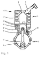
- Figures 1 and 2 each show a two-stroke engine 1 according to the invention, with a cylinder 2 and a movable piston 2 in the cylinder 3, which in a known manner via a connecting rod 4, a crank or drive shaft 5 in rotation.
- a well known two-stroke engine 1 is often used as a two-stroke engine in hand-held implements, such as rammers for soil compaction.
- a spark plug 7 is used, which generates a spark in a combustion chamber 8 at a given time, whereby the compressed by the upward movement of the piston 3 air-fuel mixture and the piston 3 down, in the direction of its bottom dead center shown in Figure 1 and thereby driving the drive shaft 5 rotatably drives.
- the piston 3 consists essentially of a lower part, which is also referred to as a piston skirt or piston shaft 9, and an upper part, which is referred to as a piston head and in the circumference piston rings 10 are used.
- the entire cylindrical outer surface of the piston 3 is referred to as a tread.
- the part of the cylindrical inner surface of the cylinder 2 is referred to as the running surface 11 of the cylinder 2, on which the piston 3 and the piston rings 10 slide.
- nozzle 12 may also be formed in the tread 11 of the cylinder 2.
- the oil supply by means of the nozzle 12 can be carried out continuously or in pulses, wherein a control according to the position of the piston 3 or even taking into account the operating state of the two-stroke engine 1 is particularly advantageous.
- a particularly effective lubrication is possible if the oil is not supplied in liquid form, but as an oil aerosol or mist.
- the finest droplets allow for a broad distribution of the oil without affecting the lubricating effect.
- the oil is supplied in liquid form to the nozzle 12 and is atomized there under pressure.
- the oil of the nozzle 12 or a correspondingly shaped outlet is already supplied as an oil aerosol and then only on the running surface 11 of the cylinder 2 and the piston shaft 9 must be addressed.
- nozzle 12 As an alternative to the nozzle 12 or a corresponding non-pressurized outlet, it is also possible to provide a plurality of outlets or nozzles, for example in the form of a nozzle ring, in order to allow oil to penetrate from below into the running surface 11 of the cylinder 2.
- the amount of oil supplied should be such that a Lubrication of the piston 3 in the cylinder 2 is reliably possible.
- leakage of the oil into the combustion chamber 8 or into a crank chamber 13 located below the piston 3 should be avoided in order to minimize oil consumption. Accordingly, it may be necessary for further moving parts of the two-stroke engine 1, in particular connecting rod bearings, to have separate lubrication, for example life lubrication, which is independent of the oil lubrication of the piston 3, or to be made of suitable materials.
- the oil supply is to be adjusted so that the piston rings 10 remain movable and can not accumulate by lack of lubrication in the receiving them annular grooves.
- the two-stroke engine according to the invention can be used particularly advantageously in a working device, in particular a manually operable working device, as shown schematically in FIG.
- the two-stroke engine 1 is sketched in the left part of FIG. Its drive shaft 5 extends from the housing of the two-stroke engine 1 into a housing 14, which surrounds a movement-changing device 15.
- the motion converting device 15 may include various types of gear drives, crank gears, etc., and serves essentially to convert directions of movement, types of movement (translational, rotational, continuous, intermittent, oscillatory, jerky, etc.) and movement speeds.
- the movement changing device 15 is sketched only schematically in FIG. 3 in the form of a toothed wheel and a dashed frame surrounding it.
- the moving components of the movement changing device 15 are lubricated by oil filled in the housing 14, which is symbolized by an oil sump 16 in FIG.
- oil Due to the high speeds of the moving components of the motion conversion device 15 oil is constantly thrown up from the oil sump 16 and swirled in the form of large and small droplets. After a short time already formed in the housing 14 from an existing oil aerosol oil mist of fine oil droplets, which wets all parts to be lubricated.
- a portion of the oil aerosol is collected by a collector 17 which is essentially an opening in the housing 14 into which the oil aerosol may enter.
- filters or porous sponge-like materials may be provided at this point to filter the oil aerosol.
- the oil aerosol from the collector 17 is guided to the nozzle 12 serving as an oil outlet.
- the conveyor 18 may be formed in a variety of ways and depending on the design of the lubricating system, the oil in liquid form or as an oil aerosol without pressure or under pressure standing transport.
- the two-stroke engine 1 is lubricated exclusively by the oil from the housing 14.
- An additional oil supply as in the prior art is therefore no longer necessary. There is no need to fuel an oil-fuel mixture or provide a separate oil reservoir.
Landscapes
- Engineering & Computer Science (AREA)
- Mechanical Engineering (AREA)
- General Engineering & Computer Science (AREA)
- Chemical & Material Sciences (AREA)
- Combustion & Propulsion (AREA)
- Lubrication Of Internal Combustion Engines (AREA)
- Lubrication Details And Ventilation Of Internal Combustion Engines (AREA)
Description
- Die Erfindung betrifft einen Zweitaktmotor gemäß dem Oberbegriff von Patentanspruch 1 sowie ein den Zweitaktmotor nutzendes Arbeitsgerät.
- Derartige Zweitaktmotoren werden aufgrund ihrer hohen spezifischen Leistung, lageunabhängigen Einsetzbarkeit und ihres niedrigen Gewichts bevorzugt bei Arbeitsgeräten, insbesondere handgeführten Arbeitsgeräten eingesetzt.
- Zur Schmierung von Zweitaktmotoren sind grundsätzlich zwei Prinzipien bekannt, nämlich eine Gemischschmierung, bei der Öl bereits vorab dem Kraftstoff in einem Mischungsverhältnis von 1:25 bis 1:100 beigemischt wird, sowie eine Getrenntschmierung, bei der Öl aus einem separaten Öltank durch eine Ölpumpe in das Kurbelgehäuse oder den Vergaserstutzen gepumpt wird. Beide Schmierungsmethoden unterstützen die lageunabhängige Einsetzbarkeit und das niedrige Gewicht der Zweitaktmotoren.
- Während bei der Gemischschmierung Öl bei jedem Tankvorgang dem Kraftstoff beigemengt werden muss, ist es bei der Getrenntschmierung erforderlich, den separaten Öltank regelmäßig nachzufüllen, da es sich bei Zweitaktmotoren grundsätzlich um eine Verlustschmierung, also ohne Ölkreislauf, handelt. Ein gewisser Anteil des Öls trägt daher nicht zur Schmierung bei, sondern wird ungenutzt verbrannt. Dadurch muss dem Motor übermäßig viel Öl zugeführt werden, was nicht zuletzt das Gesamtgewicht des Zweitaktmotors aufgrund des Ölvorrats erhöht.
- Aus der US 4,794,896 A ist ein Zweitaktmotor bekannt, bei dem Öl über einen Ölauslass in den Bereich einer Berührungsfläche zwischen einem Kolben und einem Zylinder ausbringbar ist.
- Der Erfindung liegt die Aufgabe zugrunde, einen Zweitaktmotor mit reduziertem Schmierölbedarf anzugeben.
- Die erfindungsgemäße Lösung der Aufgabe ist in Patentanspruch 1 angegeben. Danach ist der Zweitaktmotor dadurch gekennzeichnet, dass das Öl in Form eines Ölaerosols auf eine Lauffläche eines Kolbenschafts des Kolbens und auf eine Lauffläche des Zylinders ausbringbar ist.
- Es wurde festgestellt, dass die tribologische Belastung des Zweitaktmotors im Bereich der Berührungsfläche zwischen Kolben und Zylinder, also der Reibfläche zwischen dem Kolben bzw. eventuell vorhandenen Kolbenringen und dem Zylinder am größten ist. Daher ist es von enormem Vorteil, wenn nur dieser Bereich mit Öl benetzt wird, um ein Eindringen von Öl in den Verbrennungsraum und nachfolgend ein Verbrennen des Öls einerseits und einen im Kurbelraum unter dem Kolben vorhandenen Ölsumpf andererseits zu vermeiden. Durch das gezielte Ausbringen von Öl in Form eines Ölaerosols in die Berührungsfläche zwischen Kolben und Zylinder genügen bereits geringste Ölmengen, um eine ausreichende Schmierung zu erzielen.
- Bei einer besonders vorteilhaften Ausführungsform der Erfindung ist das Öl auf eine Lauffläche, das heißt eine Außenfläche eines Kolbenschafts des Kolbens und/oder auf eine Lauffläche des Zylinders ausbringbar, wobei dazu geeigneterweise ein entsprechender Ölauslass in oder unterhalb der Lauffläche des Zylinders vorgesehen sein sollte. Das Ausbringen des Öls kann dann im Takt des Motors derart erfolgen, dass zunächst Öl auf die Lauffläche des Kolbenschafts ausgebracht wird, wenn sich der Kolben im Bereich seines unteren Totpunkts befindet, und später, wenn der Kolben seinen oberen Totpunkt erreicht, ein Benetzen der Lauffläche des Zylinders erfolgt.
- Das Ölaerosol kann entweder vom Ölauslass selbst erzeugt werden oder dem Ölauslass bereits als Ölaerosol zugeführt werden.
- Besonders vorteilhaft ist es, wenn der Ölauslass in Form einer in den Zylinder gerichteten, schrägstehenden Düse ausgebildet ist. Die Düsenwirkung reicht dann in den Zylinder hinein, obwohl die Düse unterhalb der Lauffläche des Zylinders angeordnet sein kann. Dadurch ist die Düse in der Lage, die Innenfläche (Lauffläche) des Zylinders mit Öl zu benetzen.
- Eine Verbesserung des wirtschaftlichen Umgangs mit dem Schmieröl ist nach der Erfindung möglich, wenn das Ausbringen von Öl aus dem Ölauslass in Abhängigkeit von einem Lastzustand des Zweitaktmotors ansteuerbar ist. So kann zum Beispiel ein Leerlaufbetrieb ohne jegliche Schmierölzufuhr erfolgen, während im Volllastbetrieb eine erhöhte Ölzufuhr erforderlich sein kann, um die hochbeanspruchten Bauteile zu schützen.
- Der erfindungsgemäße Zweitaktmotor findet besonders vorteilhafte Verwendung in einem Arbeitsgerät, insbesondere einem handgeführten Arbeitsgerät, bei dem der Zweitaktmotor mit einer in einem Gehäuse angeordneten Bewegungswandeleinrichtung gekoppelt ist und der Zweitaktmotor durch Öl aus dem Gehäuse der Bewegungswandeleinrichtung schmierbar ist. Bei entsprechender Auslegung der Bauteile und des Schmierungssystems kann der Zweitaktmotor sogar ausschließlich durch das Öl aus dem Gehäuse schmierbar sein, ohne dass zusätzliches Schmieröl, zum Beispiel in einem separaten Öltank oder durch Beimischung in den Kraftstoff erforderlich ist.
- Durch das Mager- bzw. Minimalschmierungssystem lässt sich das Gewicht des Zweitaktmotors und damit des Arbeitsgeräts deutlich vermindern. Weiterhin sind bisher übliche Maßnahmen, wie eben das Zubereiten des Öl-Kraftstoff-Gemisches, das Bereitstellen, Reinigen und Warten eines separaten Öltanks oder das Überwachen des Ölvorrats durch entsprechende Einrichtungen nicht mehr erforderlich. Der Aufbau des Zweitaktmotors kann dadurch deutlich vereinfacht werden, was auch seine Zuverlässigkeit erhöht.
- Diese und weitere Vorteile und Merkmale der Erfindung werden nachfolgend anhand eines Beispiels unter Zuhilfenahme der begleitenden Figuren näher erläutert. Es zeigen:
- Figur 1
- einen Schnitt durch einen erfindungsgemäßen Zweitaktmotor, wobei ein Kolben im unteren Totpunkt steht;
- Figur 2
- einen Schnitt gemäß Figur 1, wobei der Kolben kurz vor dem oberen Totpunkt steht; und
- Figur 3
- schematisch den Aufbau eines den erfindungsgemäßen Zweitaktmotor verwendenden Arbeitsgeräts.
- Die Figuren 1 und 2 zeigen jeweils einen erfindungsgemäßen Zweitaktmotor 1, mit einem Zylinder 2 und einem in dem Zylinder 2 beweglichen Kolben 3, der in bekannter Weise über ein Pleuel 4 eine Kurbel- bzw. Antriebswelle 5 in Drehung versetzt.
- Ein in soweit bekannter Zweitaktmotor 1 wird häufig als Zweitaktmotor bei handgeführten Arbeitsgeräten, wie zum Beispiel Stampfern zur Bodenverdichtung eingesetzt.
- Im oberen Teil eines den Zylinder 2 umfassenden Zylindergehäuses 6 ist eine Zündkerze 7 eingesetzt, die in einem Verbrennungsraum 8 zur gegebenen Zeit einen Zündfunken erzeugt, wodurch das durch die Aufwärtsbewegung des Kolbens 3 komprimierte Luft-Kraftstoff-Gemisch verbrennt und den Kolben 3 nach unten, in Richtung seines in Figur 1 gezeigten unteren Totpunkts treibt und dadurch die Antriebswelle 5 drehend antreibt.
- Die Arbeitsweise eines Zweitaktmotors ist allgemein bekannt und soll daher nicht weiter vertieft werden.
- Der Kolben 3 besteht im wesentlichen aus einem unteren Teil, der auch als Kolbenhemd oder Kolbenschaft 9 bezeichnet wird, sowie einem oberen Teil, der als Kolbenkopf bezeichnet wird und in dessen Umfang Kolbenringe 10 eingesetzt sind.
- Die gesamte zylindrische Außenfläche des Kolbens 3 wird als Lauffläche bezeichnet. Umgekehrt wird der Teil der zylindrischen Innenfläche des Zylinders 2 als Lauffläche 11 des Zylinders 2 bezeichnet, auf dem der Kolben 3 sowie die Kolbenringe 10 gleiten.
- Unterhalb, also außerhalb der Lauffläche 11 des Zylinders 2 ist eine als Ölauslass dienende Düse 12 derart schräg eingesetzt, dass ihre Spritzrichtung in den Zylinder 2 hinein reicht. Über die Düse 12 kann somit Öl in den Zylinder 2 und vor allem auf seine Lauffläche 11 gebracht werden, wie zum Beispiel aus Figur 2 erkennbar. Alternativ kann die Düse 12 auch in der Lauffläche 11 des Zylinders 2 ausgebildet sein.
- Die Benetzung der Lauffläche 11 des Zylinders 2 setzt voraus, dass sich der Kolben 3 in der Nähe seiner in Figur 2 gezeigten oberen Totpunktstellung befindet. Wenn der Kolben 3 seine in Figur 1 gezeigte untere Totpunktstellung erreicht, deckt er die Lauffläche 11 des Zylinders 2 derart ab, dass sie nicht mehr durch die Düse 12 mit Öl benetzt werden kann. Stattdessen aber wird ein Teil des Kolbenschafts 9 freigelegt, so dass nun Öl aus der Düse 12 den Kolbenschaft 9 benetzen kann.
- Durch dieses Wechselspiel ist eine gleichmäßige Schmierung der zylindrischen Flächen 9, 11 von Zylinder 2 und Kolben 3 über den gesamten Umfang möglich.
- Es wird somit - entsprechend den Figuren 1 und 2 - entweder der rechte, Teil des Kolbenschafts 9 und damit indirekt der rechte Teil der Lauffläche 11 des Zylinders 2 oder - bei Stellung des Kolbens 3 im oberen Totpunkt - der linke Teil der Lauffläche 11 des Zylinders 2 und somit indirekt auch der linke Teil des Kolbenschafts 9 geschmiert. Da auch die Kolbenringe 10 die geschmierten Bereiche der Lauffläche 11 des Zylinders 2 erreichen, werden sie ebenfalls mit Öl versorgt.
- Die Ölzuführung mittels der Düse 12 kann kontinuierlich oder impulsweise erfolgen, wobei eine Ansteuerung entsprechend der Stellung des Kolbens 3 oder auch unter Berücksichtigung des Betriebszustands des Zweitaktmotors 1 besonders vorteilhaft ist.
- Eine besonders effektive Schmierung ist dann möglich, wenn das Öl nicht in flüssiger Form, sondern als Ölaerosol bzw. -nebel zugeführt wird. Die feinsten Tröpfchen lassen eine breite Verteilung des Öls zu, ohne dass die Schmierwirkung beeinträchtigt wäre.
- Somit ist es bei einer Ausführungsform der Erfindung vorgesehen, dass das Öl in flüssiger Form zu der Düse 12 zugeführt und dort unter Druck vernebelt wird. Alternativ ist es möglich, dass das Öl der Düse 12 bzw. einem entsprechend gestalteten Auslass bereits als Ölaerosol zugeführt wird und dann nur noch auf die Lauffläche 11 des Zylinders 2 bzw. den Kolbenschaft 9 gerichtet werden muss.
- Alternativ zu der Düse 12 bzw. einem entsprechenden, nicht druckbeaufschlagten Auslass ist es auch möglich, mehrere Auslässe bzw. Düsen, zum Beispiel in Form eines Düsenrings vorzusehen, um ein Eindringen von Öl von unten in die Lauffläche I1 des Zylinders 2 zu ermöglichen.
- Die Menge des zugeführten Öls sollte derart bemessen sein, dass eine Schmierung des Kolbens 3 im Zylinder 2 zuverlässig möglich ist. Ein Austreten des Öls in den Verbrennungsraum 8 oder in einen unter dem Kolben 3 liegenden Kurbelraum 13 sollte jedoch zur Minimierung des Ölverbrauchs vermieden werden. Dementsprechend kann es erforderlich sein, dass weitere bewegliche Teile des Zweitaktmotors 1, insbesondere Pleuellager, eine separate Schmierung, zum Beispiel eine Lebensdauerschmierung, die unabhängig von der Ölschmierung des Kolbens 3 ist, erhalten müssen oder aus geeigneten Materialien anzufertigen sind.
- Die Ölzuführung ist derart einzustellen, dass die Kolbenringe 10 beweglich bleiben und sich nicht durch Mangelschmierung in den sie aufnehmenden Ringnuten festsetzen können. Um den Ölverbrauch noch weiter zu reduzieren, kann es notwendig sein, die Kolbenringe 10 als sogenannte einseitige Trapezringe auszulegen und den Kolbenschaft 9 mit einer Notlaufbeschichtung, zum Beispiel mit Graphal® , zu versehen.
- Der erfindungsgemäße Zweitaktmotor kann besonders vorteilhaft bei einem Arbeitsgerät, insbesondere einem von Hand führbaren Arbeitsgerät eingesetzt werden, wie es in Figur 3 schematisch dargestellt ist.
- Der Zweitaktmotor 1 ist im linken Teil von Figur 3 skizziert. Seine Antriebswelle 5 erstreckt sich aus dem Gehäuse des Zweitaktmotors 1 in ein Gehäuse 14, das eine Bewegungswandeleinrichtung 15 umgibt. Die Bewegungswandeleinrichtung 15 kann verschiedene Arten von Zahnradgetrieben, Kurbelgetrieben usw. aufweisen und dient im wesentlichen zum Wandeln von Bewegungsrichtungen, Bewegungsarten (translatorisch, rotatorisch; kontinuierlich, intermittierend, oszillierend, stoßartig, etc.) und Bewegungsgeschwindigkeiten. Die Bewegungswandeleinrichtung 15 ist in Figur 3 lediglich schematisch in Form eines Zahnrads und eines dieses umgebenden, gestrichelten Rahmens skizziert.
- Die sich bewegenden Bauteile der Bewegungswandeleinrichtung 15 werden durch in das Gehäuse 14 eingefülltes Öl geschmiert, das in Figur 3 durch einen Ölsumpf 16 symbolisiert wird.
- Aufgrund der hohen Geschwindigkeiten der sich bewegenden Bauteile der Bewegungswandeleinrichtung 15 wird ständig Öl aus dem Ölsumpf 16 hochgeschleudert und in Form von großen und kleinen Tröpfchen verwirbelt. Nach kurzer Zeit bereits bildet sich in dem Gehäuse 14 ein aus Ölaerosol bestehender Ölnebel aus feinsten Öltröpfchen aus, der alle zu schmierenden Teile benetzt.
- Ein Teil des Ölaerosols wird durch eine Sammeleinrichtung 17 gesammelt, die im wesentlichen eine Öffnung im Gehäuse 14 darstellt, in die das Ölaerosol eintreten kann. Gegebenenfalls können an dieser Stelle Filter oder poröse schwammähnliche Materialien vorgesehen werden, um das Ölaerosol zu filtern.
- Über eine Fördereinrichtung 18 wird das Ölaerosol von der Sammeleinrichtung 17 zu der als Ölauslass dienenden Düse 12 geführt. Die Fördereinrichtung 18 kann in vielfältiger Weise ausgebildet sein und je nach Auslegung des Schmiersystems das Öl in flüssiger Form oder als Ölaerosol drucklos oder unter Druck stehend transportieren.
- Bei entsprechender Auslegung ist es bei dem Arbeitsgerät möglich, dass der Zweitaktmotor 1 ausschließlich durch das Öl aus dem Gehäuse 14 geschmiert wird. Eine zusätzliche Ölzuführung wie beim Stand der Technik ist damit nicht mehr erforderlich. Weder muss ein Öl-Kraftstoff-Gemisch getankt noch ein separater Ölbehälter vorgesehen werden.
Claims (8)
- Zweitaktmotor (1), mit einer Ölschmierung für wenigstens einen Zylinder (2) und einen in dem Zylinder (2) beweglichen Kolben (3), wobei- das dem Zweitaktmotor (1) zum Schmieren zugeführte Öl ausschließlich in Form eines Ölaerosols im Bereich einer Berührungsfläche zwischen dem Kolben (3) und dem Zylinder (2) auf eine Lauffläche eines Kolbenschafts (9) des Kolbens (3) und auf eine Lauffläche (11) des Zylinders (2) ausgebracht wird;- in oder unterhalb der Lauffläche (11) des Zylinders (2) ein mit einer Fördereinrichtung (18) gekoppelter Ölauslass (12) vorgesehen ist, durch den das Ölaerosol auf die Lauffläche des Kolbenschafts (9) sowie auf die Lauffläche (11) des Zylinders (2) ausgebracht wird,dadurch gekennzeichnet, dass- das Ölaerosol aus dem Ölauslass (12) wechselweise auf die Lauffläche des Kolbenschafts (9) ausgebracht wird, wenn sich der Kolben (3) in der Nähe seines unteren Totpunkts befindet, oder auf die Lauffläche (11) des Zylinders (2) ausgebracht wird, wenn sich der Kolben (3) in der Nähe seines oberen Totpunkts befindet;- die Menge des zugeführten Öls derart bemessen ist, dass ein Austreten des Öls in einen Verbrennungsraum (8) oder in einen unter dem Kolben (3) liegenden Kurbelraum (13) vermieden wird;- der Kolben (3) über ein Pleuel (4) und ein Pleuellager mit einer Kurbelwelle (5) gekoppelt ist; und dass- das Pleuellager lebensdauergeschmiert ist oder eine keine zusätzliche Schmierung erfordernde Materialpaarung aufweist.
- Zweitaktmotor nach Anspruch 1, dadurch gekennzeichnet, dass das dem Ölauslass (12) zugeführte Öl ein Ölaerosol ist.
- Zweitaktmotor nach einem der Ansprüche 1 oder 2, dadurch gekennzeichnet, dass der Ölauslass in Form einer in den Zylinder (2) gerichteten Düse (12) oder eines Düsenrings ausgebildet ist.
- Zweitaktmotor nach einem der Ansprüche 1 bis 3, dadurch gekennzeichnet, dass das Ausbringen von Ölaerosol aus dem Ölauslass (12) in Abhängigkeit von einem Lastzustand des Zweitaktmotors (1) angesteuert wird.
- Verwendung eines Zweitaktmotors (1) nach einem der Ansprüche 1 bis 4 in einem Arbeitsgerät mit einer in einem Gehäuse (14) angeordneten Bewegungswandeleinrichtung (15) zum Wandeln einer von dem Zweitaktmotor (1) erzeugten Drehbewegung in eine Arbeitsbewegung;
wobei- der Zweitaktmotor (1) an oder in dem Gehäuse (14) angeordnet ist;- das Gehäuse (14) mit Öl zur Schmierung der Bewegungswandeleinrichtung (15) befüllt ist; und- der Zweitaktmotor (1) durch Zuführen des Öls aus dem Gehäuse (14) zu dem Ölauslass (12) geschmiert wird. - Verwendung nach Anspruch 5, dadurch gekennzeichnet, dass der Zweitaktmotor (1) ausschließlich durch das Öl aus dem Gehäuse (14) geschmiert wird.
- Verwendung nach Anspruch 5 oder 6, dadurch gekennzeichnet, dass die Fördereinrichtung (18) zum Fördern von Öl aus dem Gehäuse (14) zu dem Zweitaktmotor (1) dient.
- Verwendung nach einem der Ansprüche 5 bis 7, dadurch gekennzeichnet, dass das Öl ein Ölaerosol ist, welches in dem Gehäuse (14) durch die Bewegungswandeleinrichtung (15) erzeugt wird.
Applications Claiming Priority (3)
| Application Number | Priority Date | Filing Date | Title |
|---|---|---|---|
| DE10045725 | 2000-09-15 | ||
| DE10045725A DE10045725B4 (de) | 2000-09-15 | 2000-09-15 | Zweitaktmotor mit einer Ölschmierung |
| PCT/EP2001/010602 WO2002023016A1 (de) | 2000-09-15 | 2001-09-13 | Zweitaktmotor mit minimalschmierung |
Publications (2)
| Publication Number | Publication Date |
|---|---|
| EP1317606A1 EP1317606A1 (de) | 2003-06-11 |
| EP1317606B1 true EP1317606B1 (de) | 2006-06-21 |
Family
ID=7656353
Family Applications (1)
| Application Number | Title | Priority Date | Filing Date |
|---|---|---|---|
| EP01974251A Expired - Lifetime EP1317606B1 (de) | 2000-09-15 | 2001-09-13 | Zweitaktmotor mit minimalschmierung |
Country Status (5)
| Country | Link |
|---|---|
| US (1) | US6932046B2 (de) |
| EP (1) | EP1317606B1 (de) |
| JP (1) | JP2004509261A (de) |
| DE (2) | DE10045725B4 (de) |
| WO (1) | WO2002023016A1 (de) |
Families Citing this family (12)
| Publication number | Priority date | Publication date | Assignee | Title |
|---|---|---|---|---|
| DE50207748D1 (de) * | 2001-12-13 | 2006-09-14 | Staeubli Ag Pfaeffikon | Verfahren und vorrichtung zur verbindung von mehreren fäden, insbesondere von fadenenden |
| US20040198464A1 (en) * | 2003-03-04 | 2004-10-07 | Jim Panian | Wireless communication systems for vehicle-based private and conference calling and methods of operating same |
| DE102004019630A1 (de) | 2004-04-22 | 2005-11-17 | Wacker Construction Equipment Ag | Ölversorgung für einen Verbrennungsmotor |
| US7360511B2 (en) | 2004-06-10 | 2008-04-22 | Achates Power, Inc. | Opposed piston engine |
| US7156056B2 (en) * | 2004-06-10 | 2007-01-02 | Achates Power, Llc | Two-cycle, opposed-piston internal combustion engine |
| US20070017803A1 (en) * | 2005-07-22 | 2007-01-25 | Heraeus, Inc. | Enhanced sputter target manufacturing method |
| US7475666B2 (en) * | 2006-09-07 | 2009-01-13 | Heimbecker John A | Stroke control assembly |
| US20080060628A1 (en) * | 2006-09-07 | 2008-03-13 | Heimbecker John A | Self-lubricating piston |
| DE102008035084A1 (de) * | 2008-07-28 | 2010-02-04 | Wacker Neuson Se | Schlaggerät mit Schlagwerk-Schmiervorrichtung |
| US8550041B2 (en) * | 2009-02-20 | 2013-10-08 | Achates Power, Inc. | Cylinder and piston assemblies for opposed piston engines |
| US8539918B2 (en) * | 2009-02-20 | 2013-09-24 | Achates Power, Inc. | Multi-cylinder opposed piston engines |
| US9328692B2 (en) * | 2009-02-20 | 2016-05-03 | Achates Power, Inc. | Opposed piston engines with controlled provision of lubricant for lubrication and cooling |
Family Cites Families (18)
| Publication number | Priority date | Publication date | Assignee | Title |
|---|---|---|---|---|
| US1603173A (en) * | 1924-12-06 | 1926-10-12 | Miller Improved Gas Engine Com | Internal-combustion engine |
| DE833880C (de) * | 1949-11-01 | 1952-03-13 | Willy Lehmann | Zusatzschmierung fuer Arbeitskolben |
| US3204619A (en) * | 1962-07-02 | 1965-09-07 | American Mach & Foundry | Internal combustion engine |
| GB1296830A (de) * | 1969-02-21 | 1972-11-22 | ||
| JPS6220611A (ja) * | 1985-07-19 | 1987-01-29 | Honda Motor Co Ltd | 2サイクルエンジンの潤滑装置 |
| GB2211581B (en) * | 1987-11-06 | 1991-11-06 | Ind Tech Res Inst | A lubricating device for two-stroke engine |
| DE4034162C1 (de) * | 1990-10-26 | 1992-06-04 | Michael L. 8830 Treuchtlingen De Zettner | |
| US5241932A (en) * | 1991-12-02 | 1993-09-07 | Ryobi Outdoor Products | Operator carried power tool having a four-cycle engine |
| DE4243571C2 (de) | 1992-12-22 | 1997-05-28 | Opel Adam Ag | Ölversorgung für den Kolben einer Hubkolbenbrennkraftmaschine |
| JPH06229219A (ja) * | 1993-02-03 | 1994-08-16 | Yamaha Motor Co Ltd | 2サイクルエンジンの潤滑装置 |
| DE4323262A1 (de) * | 1993-07-12 | 1995-01-26 | Fev Motorentech Gmbh & Co Kg | Verfahren und Anordnung für die Schmiermittelversorgung einer Hubkolbenmaschine |
| US5375573A (en) * | 1993-09-09 | 1994-12-27 | Ford Motor Company | Lubrication of two-stroke internal combustion engines |
| US5581891A (en) * | 1994-08-12 | 1996-12-10 | Black & Decker Inc. | Hedge trimmer with combination shearing and sawing blade assembly |
| EP0781901A1 (de) * | 1995-12-29 | 1997-07-02 | Yamaha Hatsudoki Kabushiki Kaisha | Schmierungsanordnung für Brennkraftmaschine |
| US5826556A (en) * | 1997-04-24 | 1998-10-27 | Brunswick Corporation | Engine lubrication circuit with alternating lubrication paths |
| IT1298936B1 (it) | 1998-02-23 | 2000-02-07 | Gilardoni Vittorio S P A | Metodo e dispositivo per effettuare l'iniezione di fluidi combustibili e/o lubrificanti in un motore a combustione interna |
| CA2350105A1 (en) | 1998-11-05 | 2000-05-18 | Hans Jensen Lubricators A/S | Lubrication system for large diesel engines |
| WO2000053900A1 (en) | 1999-03-11 | 2000-09-14 | Outboard Marine Corporation | Oil injection system |
-
2000
- 2000-09-15 DE DE10045725A patent/DE10045725B4/de not_active Expired - Fee Related
-
2001
- 2001-09-13 DE DE50110278T patent/DE50110278D1/de not_active Expired - Lifetime
- 2001-09-13 WO PCT/EP2001/010602 patent/WO2002023016A1/de not_active Ceased
- 2001-09-13 US US10/363,845 patent/US6932046B2/en not_active Expired - Fee Related
- 2001-09-13 EP EP01974251A patent/EP1317606B1/de not_active Expired - Lifetime
- 2001-09-13 JP JP2002527638A patent/JP2004509261A/ja active Pending
Also Published As
| Publication number | Publication date |
|---|---|
| DE10045725A1 (de) | 2002-04-04 |
| US20040011308A1 (en) | 2004-01-22 |
| US6932046B2 (en) | 2005-08-23 |
| WO2002023016A1 (de) | 2002-03-21 |
| DE50110278D1 (de) | 2006-08-03 |
| DE10045725B4 (de) | 2005-05-04 |
| EP1317606A1 (de) | 2003-06-11 |
| JP2004509261A (ja) | 2004-03-25 |
Similar Documents
| Publication | Publication Date | Title |
|---|---|---|
| EP1317606B1 (de) | Zweitaktmotor mit minimalschmierung | |
| DE69224844T2 (de) | Handmaschinenwerkzeug mit einer viertaktbrennkraftmaschine | |
| EP0659233B1 (de) | Verfahren und anordnung für die schmiermittelversorgung einer hubkolbenmaschine | |
| EP2273078A1 (de) | Kolben für einen Zylinder eines Grossmotors sowie Schmiervorrichtung und Schmierverfahren mit einem solchen Kolben | |
| DE3639389A1 (de) | Kettenspann- und -schmiervorrichtung | |
| EP0625389B1 (de) | Giessgarnitur für eine Druckgiessmaschine | |
| EP1738062B1 (de) | Ölversorgung für einen verbrennungsmotor | |
| DE2719228A1 (de) | Einspritzeinrichtung fuer eine innenbrennkraftmaschine | |
| DE10045726B4 (de) | Schmiersystem für Arbeitsgerät mit Verbrennungsmotor | |
| DE2803774A1 (de) | Kraftstoff-einspritzduese fuer einspritz-brennkraftmaschinen | |
| DE3913764C2 (de) | ||
| EP1350929B2 (de) | Verfahren zum Schmieren einer Lauffläche einer Zylinderwand eines Zylinders einer Hubkolbenbrennkraftmaschine | |
| DE102013002743B4 (de) | Vorrichtung zur Zylinderschmierung | |
| DE19902928C1 (de) | Schmiersystem für die Kolbengruppe einer Brennkraftmaschine sowie Verfahren zu dessen Steuerung | |
| DE2402837A1 (de) | Schmiersystem fuer den zweitakt-verbrennungsmotor | |
| DE102014008116A1 (de) | Verfahren zur schmiermittelversorgung eines getriebes, getriebeschmiereinrichtung, getriebeeinheit und baumaschine | |
| DE102012111249B3 (de) | Viertaktmotor ohne Kurbelwelle und Ventile | |
| DE2110778B2 (de) | Vorrichtung zum einfuehren von brennstoff in eine zweitakt-brennkraftmaschine | |
| EP1275843A2 (de) | Brennkraftmaschine, insbesondere für Kraftfahrzeuge | |
| DE2821141C2 (de) | ||
| EP0210976B1 (de) | Einzylinder-Zweitakt-Brennkraftmaschine mit Kurbelkastenspülung | |
| DE1930834C3 (de) | Einrichtung zum Abführen von Öl und Verbrennungsrückständen bei einer Kreuzkopfbrennkraftmaschine | |
| DE2950634A1 (de) | Brennkraftmaschine mit einer einspritzpumpenanordnung | |
| DE10210979A1 (de) | Dieselbär, Hydraulikbär oder dgl. | |
| DE4438867A1 (de) | Schmieranordnung am Kolben eines Hubkolbentriebes |
Legal Events
| Date | Code | Title | Description |
|---|---|---|---|
| PUAI | Public reference made under article 153(3) epc to a published international application that has entered the european phase |
Free format text: ORIGINAL CODE: 0009012 |
|
| 17P | Request for examination filed |
Effective date: 20030314 |
|
| AK | Designated contracting states |
Designated state(s): AT BE CH CY DE DK ES FI FR GB GR IE IT LI LU MC NL PT SE TR |
|
| AX | Request for extension of the european patent |
Extension state: AL LT LV MK RO SI |
|
| RBV | Designated contracting states (corrected) |
Designated state(s): AT BE CH DE LI SE |
|
| GRAP | Despatch of communication of intention to grant a patent |
Free format text: ORIGINAL CODE: EPIDOSNIGR1 |
|
| RBV | Designated contracting states (corrected) |
Designated state(s): CH DE LI SE |
|
| GRAS | Grant fee paid |
Free format text: ORIGINAL CODE: EPIDOSNIGR3 |
|
| GRAA | (expected) grant |
Free format text: ORIGINAL CODE: 0009210 |
|
| AK | Designated contracting states |
Kind code of ref document: B1 Designated state(s): CH DE LI SE |
|
| REG | Reference to a national code |
Ref country code: CH Ref legal event code: EP |
|
| REG | Reference to a national code |
Ref country code: CH Ref legal event code: NV Representative=s name: E. BLUM & CO. PATENTANWAELTE |
|
| REF | Corresponds to: |
Ref document number: 50110278 Country of ref document: DE Date of ref document: 20060803 Kind code of ref document: P |
|
| REG | Reference to a national code |
Ref country code: SE Ref legal event code: TRGR |
|
| PLBE | No opposition filed within time limit |
Free format text: ORIGINAL CODE: 0009261 |
|
| STAA | Information on the status of an ep patent application or granted ep patent |
Free format text: STATUS: NO OPPOSITION FILED WITHIN TIME LIMIT |
|
| 26N | No opposition filed |
Effective date: 20070322 |
|
| REG | Reference to a national code |
Ref country code: CH Ref legal event code: PFA Owner name: WACKER CONSTRUCTION EQUIPMENT AG Free format text: WACKER CONSTRUCTION EQUIPMENT AG#PREUSSENSTRASSE 41#80809 MUENCHEN (DE) -TRANSFER TO- WACKER CONSTRUCTION EQUIPMENT AG#PREUSSENSTRASSE 41#80809 MUENCHEN (DE) |
|
| REG | Reference to a national code |
Ref country code: CH Ref legal event code: PFA Owner name: WACKER NEUSON SE Free format text: WACKER CONSTRUCTION EQUIPMENT AG#PREUSSENSTRASSE 41#80809 MUENCHEN (DE) -TRANSFER TO- WACKER NEUSON SE#PREUSSENSTRASSE 41#80809 MUENCHEN (DE) |
|
| REG | Reference to a national code |
Ref country code: CH Ref legal event code: PUE Owner name: WACKER NEUSON PRODUKTION GMBH & CO. KG Free format text: WACKER NEUSON SE#PREUSSENSTRASSE 41#80809 MUENCHEN (DE) -TRANSFER TO- WACKER NEUSON PRODUKTION GMBH & CO. KG#PREUSSENSTRASSE 41#80809 MUENCHEN (DE) |
|
| REG | Reference to a national code |
Ref country code: DE Ref legal event code: R082 Ref document number: 50110278 Country of ref document: DE Representative=s name: MUELLER - HOFFMANN & PARTNER PATENTANWAELTE, DE |
|
| REG | Reference to a national code |
Ref country code: DE Ref legal event code: R082 Ref document number: 50110278 Country of ref document: DE Representative=s name: MUELLER HOFFMANN & PARTNER PATENTANWAELTE MBB, DE Effective date: 20120326 Ref country code: DE Ref legal event code: R081 Ref document number: 50110278 Country of ref document: DE Owner name: WACKER NEUSON PRODUKTION GMBH & CO. KG, DE Free format text: FORMER OWNER: WACKER NEUSON SE, 80809 MUENCHEN, DE Effective date: 20120326 |
|
| PGFP | Annual fee paid to national office [announced via postgrant information from national office to epo] |
Ref country code: CH Payment date: 20150922 Year of fee payment: 15 Ref country code: DE Payment date: 20150923 Year of fee payment: 15 |
|
| PGFP | Annual fee paid to national office [announced via postgrant information from national office to epo] |
Ref country code: SE Payment date: 20150922 Year of fee payment: 15 |
|
| REG | Reference to a national code |
Ref country code: DE Ref legal event code: R119 Ref document number: 50110278 Country of ref document: DE |
|
| PG25 | Lapsed in a contracting state [announced via postgrant information from national office to epo] |
Ref country code: SE Free format text: LAPSE BECAUSE OF NON-PAYMENT OF DUE FEES Effective date: 20160914 |
|
| REG | Reference to a national code |
Ref country code: CH Ref legal event code: PL |
|
| REG | Reference to a national code |
Ref country code: SE Ref legal event code: EUG |
|
| PG25 | Lapsed in a contracting state [announced via postgrant information from national office to epo] |
Ref country code: LI Free format text: LAPSE BECAUSE OF NON-PAYMENT OF DUE FEES Effective date: 20160930 Ref country code: DE Free format text: LAPSE BECAUSE OF NON-PAYMENT OF DUE FEES Effective date: 20170401 Ref country code: CH Free format text: LAPSE BECAUSE OF NON-PAYMENT OF DUE FEES Effective date: 20160930 |