EP1317895A2 - Schwenkmechanik für ein Sofa - Google Patents
Schwenkmechanik für ein Sofa Download PDFInfo
- Publication number
- EP1317895A2 EP1317895A2 EP02024867A EP02024867A EP1317895A2 EP 1317895 A2 EP1317895 A2 EP 1317895A2 EP 02024867 A EP02024867 A EP 02024867A EP 02024867 A EP02024867 A EP 02024867A EP 1317895 A2 EP1317895 A2 EP 1317895A2
- Authority
- EP
- European Patent Office
- Prior art keywords
- sofa
- movable
- fixed
- sofa part
- sliding guide
- Prior art date
- Legal status (The legal status is an assumption and is not a legal conclusion. Google has not performed a legal analysis and makes no representation as to the accuracy of the status listed.)
- Granted
Links
- 238000006073 displacement reaction Methods 0.000 description 2
- 230000001154 acute effect Effects 0.000 description 1
- 230000000295 complement effect Effects 0.000 description 1
Images


Classifications
-
- A—HUMAN NECESSITIES
- A47—FURNITURE; DOMESTIC ARTICLES OR APPLIANCES; COFFEE MILLS; SPICE MILLS; SUCTION CLEANERS IN GENERAL
- A47C—CHAIRS; SOFAS; BEDS
- A47C17/00—Sofas; Couches; Beds
- A47C17/04—Seating furniture, e.g. sofas, couches, settees, or the like, with movable parts changeable to beds; Chair beds
- A47C17/34—Joining seats, chairs, or couches to form beds
- A47C17/36—Changing corner couches into a double bed
Definitions
- the invention relates to a pivot mechanism for a sofa with the features of Preamble of claim 1.
- From DE 195 34 837 A1 is a plan view in approximately L-shaped sofa with a fixed sofa part and a movable sofa part known.
- the movable one Sofateil is made of a position extending the fixed part of the sofa in one fixed sofa part to a roughly square in plan view or too quarter-circular lying surface complementary position and back pivotable.
- For pivotal connection is a foot of the movable Sofateils pivotally connected to one foot of the fixed sofa section, with the two feet at a common corner of the two sofa pieces are arranged.
- the two feet form a pivot joint of the known Sofas.
- the invention is based on the object, a swivel mechanism for a sofa to propose, avoiding the grinding marks on the ground.
- the pivoting mechanism according to the invention has a pivot joint for pivotally connecting a movable sofa part to a fixed one Sofafile on. Furthermore, the pivoting mechanism according to the invention has a Sliding guide for the movable sofa part, with which the movable sofa part slidably guided in a distance from the fixed sofa part. Of the Distance between the movable sofa part and the fixed sofa part allows a pivoting of the movable sofa part to, for example, a Corner of the fixed sofa section around.
- the sliding guide is the pivoting mechanism according to the invention designed and arranged so that they the movable sofa part raises when the movable sofa part is at a distance from fixed sofa part is moved.
- the movable sofa part is characterized in Levitating, so that it does not pivot on a floor grinds. This will avoid sanding marks on the floor.
- the pivoting can be done with little force, as when pivoting due to the raised movable sofa part no frictional force between the floor and the movable sofa part acts. This refers to the lifting to an intended position of use of the pivoting mechanism.
- An embodiment of the invention provides a pivoting angle limiting, the a tilt angle so limited that the movable sofa part in the two provided positions is pivoted.
- a Bow guide as sliding guide before.
- the bowing runs in one intended use position of the pivoting mechanism, for example, first in approximately horizontally and with increasing distance from the fixed sofa part bent upwards.
- Another embodiment of the invention provides a step guide that the movable sofa part when moving at a distance from the fixed one Sofateil raises in one or more stages and lifts off the ground.
- the Sliding guide can be on the steps or also altogether diagonally upwards run and can therefore also be referred to as inclined guide.
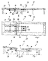
- the figures show seat frames of the sofa without upholstery and without backrest or armrests.
- the illustrated in the drawing, generally designated 10, according to the invention Sofa has a fixed sofa part 12 and a movable sofa part 14 on.
- the two sofa parts 12, 14 are provided with an inventive Swivel mechanism 16 connected to the lower sides of the two sofa parts 12, 14th is arranged.
- the pivot mechanism 16 has a pivot joint 18 which is attached to an underside of the fixed sofa part 12.
- a Pivot axis 20 of the pivot joint 18 extends vertically and has a same distance from a front edge 22 as from a side edge 24 of the fixed sofa part 12.
- the pivoting mechanism 16 has a Sliding guide 26 which in the in FIGS. 1 to 6 and described embodiment of the invention, two round bars 28 and four Roll blocks 30 includes.
- the round rods 28 are rigid with the pivot joint 18 connected, they are in a direction to the side of the pivot joint 18 from.
- the round rods 28 are bent, they run in the area of Swivel joint 18 horizontally and with increasing distance from Swivel joint 18 curved upwards. Because of the curved course of the Round bars 28 forms the sliding guide 26 a bow guide.
- the roller blocks 30 each have two rollers whose circumference is concave for example, is designed as a V-groove.
- the two rolls of a roll block 30 engage around a round rod 28 at opposite locations and lead the respective roller block 30 in the longitudinal direction of the round rod 28 slidably.
- the Round rods 28 thus form rails for the roller blocks 30.
- the roller blocks 30 are attached to an underside of the movable sofa member 14.
- the four Roller blocks 30 are arranged at corners of an imaginary rectangle, they are each two roller blocks 30 slidably guided on a round rod 28.
- End stops 32 on the pivot joint 18 distal ends of Round rods 18 limit a displacement of the roller blocks 30 and prevent the movable sofa part 14 inadvertently from the Round rods 28 can be moved down.
- the function of the pivoting mechanism 16 is the following: In the in Figures 1 and 2 shown position is the movable sofa part 14 in Extension of the fixed sofa part 12 at the side edge 24. To the movable Sofateil 14 opposite the fixed sofa part 12 to will pivot the movable sofa member 14 in the longitudinal direction of Sliding guide 26 from the fixed sofa part 12 shifted away. At this Displacement is due to the upward curved course of the Round rods 28 of the sliding guide 26, the movable sofa part 14 is raised. This position is shown in FIG.
- FIGS. 5 and 6 In the spaced from the fixed part of the sofa 12 position can be the raised, movable sofa part 14 by means of the pivot joint 18 free swing.
- the movable sofa part 14 is shown in FIG Position away to the front edge 22 of the fixed sofa part 12th pivoted and then back to the fixed sofa part 12th zoom moved.
- FIGS. 5 and 6 When moving to the fixed Sofateil 12 lowers zoom the movable sofa part 14 due to the curved course of the Round rods 28 off again, leaving it with his feet 34 on a ground gets up.
- FIGS. 5 and 6 this completes movable sofa part 14 the fixed sofa part 12 to a top view L-shaped Angle sofa. Swiveling back into FIGS. 1 and 2 Position is reversed.
- the swivel angle of the swivel mechanism 26 and thus of the movable sofa part 14 is shown in the and described embodiment of the invention 90 degrees.
- the swivel angle may be chosen differently for other sofa designs.
- the swivel joint 18 of the pivoting mechanism 16 has a not visible in the drawing Schwenkwinkelbegrenzung on, the pivot angle to the above value limited.
- inventive sofa 10 has as well as in Figures 1 to 6 illustrated and described above sofa 10 a Swivel mechanism 16 with a pivot joint 18, which is a movable Sofateil 14 with a fixed sofa part 12 connects. Also, the Swing mechanism 16 a sliding guide 26, which, however, not in Figure 7 is designed as a bow guide, but as a stepped and / or inclined guide.
- the sliding guide 26 of the sofa 10 shown in FIG. 7 has two steps 38 on, in which the sliding guide 26 obliquely away from the fixed sofa part 12 leading upwards at an acute angle to an imaginary horizontal.
- the sliding guide 26 runs horizontally or parallel to the floor 36.
- Guide rods 40 of the sliding guide 16 are in this embodiment formed as L or T profiles, the rollers of the roller blocks 30 are cylindrical.
- the sofa 10 from FIG. 7 is the same that is formed from Figures 1 to 6 and it is to avoid Repetitions to that extent with regard to Figure 7 to the corresponding statements refer to Figures 1 to 6. Same components will be the same Reference numbers used.
- the function of the sofa 10 shown in FIG. 7 is the same as that of FIG Figures 1 to 6 illustrated sofas 10: Is the movable sofa part 14 at the Slide guide 26 moved away from the fixed sofa part 12, lifts the Sliding guide 26, the movable sofa part 14 from the bottom 36, so that the movable sofa part 14 freely around the corner of the fixed sofa part 12 around can be swiveled. Subsequently, the movable sofa part 14 is again pushed to the fixed part of the sofa 12 and lowers it on the Floor 36 off.
Landscapes
- Health & Medical Sciences (AREA)
- General Health & Medical Sciences (AREA)
- Nursing (AREA)
- Chairs For Special Purposes, Such As Reclining Chairs (AREA)
- Chair Legs, Seat Parts, And Backrests (AREA)
- Acyclic And Carbocyclic Compounds In Medicinal Compositions (AREA)
- Threshing Machine Elements (AREA)
- Special Chairs (AREA)
Abstract
Description
- Figuren 1, 3 und 6
- ein erfindungsgemäßes Sofa in Ansicht von vorn in verschiedenen Positionen;
- Figuren 2, 4 und 5
- das Sofa aus Figuren 1, 3 und 6 in Draufsicht und unterschiedlichen Positionen; und
- Figur 7
- eine abgewandelte Ausführungsform der Erfindung in einer Figur 3 entsprechenden Ansicht von vorn.
Claims (4)
- Schwenkmechanik für ein Sofa, wobei das Sofa ein feststehendes Sofateil und ein bewegbares Sofateil, das zwischen einer das feststehende Sofateil verlängernden und einer das feststehende Sofateil zu einem Winkelsofa ergänzenden Position hin- und her bewegbar ist, aufweist, wobei die Schwenkmechanik ein Schwenkgelenk zum schwenkbaren Verbinden der beiden Sofateile aufweist, dadurch gekennzeichnet, dass die Schwenkmechanik (16) eine Schiebeführung (26) für das bewegbare Sofateil (14) aufweist, mit der das bewegbare Sofateil (14) in einen Abstand vom feststehenden Sofateil (12) verschiebbar geführt ist, und dass die Schiebeführung (26) das bewegbare Sofateil (14) anhebt, wenn das bewegbare Sofateil (14) in Abstand vom feststehenden Sofateil (12) verschoben wird.
- Schwenkmechanik nach Anspruch 1, dadurch gekennzeichnet, dass die Schwenkmechanik (16) eine Schwenkwinkelbegrenzung aufweist.
- Schwenkmechanik nach Anspruch 1 oder 2, dadurch gekennzeichnet, dass die Schiebeführung (16) eine Bogenführung aufweist.
- Schwenkmechanik nach Anspruch 1 oder 2, dadurch gekennzeichnet, dass die Schiebeführung (16) eine Stufenführung aufweist.
Applications Claiming Priority (2)
| Application Number | Priority Date | Filing Date | Title |
|---|---|---|---|
| DE20119684U DE20119684U1 (de) | 2001-12-05 | 2001-12-05 | Schwenkmechanik für ein Sofa |
| DE20119684U | 2001-12-05 |
Publications (3)
| Publication Number | Publication Date |
|---|---|
| EP1317895A2 true EP1317895A2 (de) | 2003-06-11 |
| EP1317895A3 EP1317895A3 (de) | 2003-12-03 |
| EP1317895B1 EP1317895B1 (de) | 2006-06-14 |
Family
ID=7964772
Family Applications (1)
| Application Number | Title | Priority Date | Filing Date |
|---|---|---|---|
| EP02024867A Expired - Lifetime EP1317895B1 (de) | 2001-12-05 | 2002-11-08 | Schwenkmechanik für ein Sofa |
Country Status (4)
| Country | Link |
|---|---|
| EP (1) | EP1317895B1 (de) |
| AT (1) | ATE329510T1 (de) |
| DE (2) | DE20119684U1 (de) |
| ES (1) | ES2266388T3 (de) |
Citations (1)
| Publication number | Priority date | Publication date | Assignee | Title |
|---|---|---|---|---|
| DE19534837A1 (de) | 1995-09-20 | 1997-03-27 | Benz Rolf Ag | Sitz- und Liegemöbel |
Family Cites Families (14)
| Publication number | Priority date | Publication date | Assignee | Title |
|---|---|---|---|---|
| DE4236798C1 (en) | 1992-10-30 | 1993-09-23 | Hermann Hummel Polstermoebel Gmbh, 96242 Sonnefeld, De | Upholstered sectional furniture such as sofa - has top part movable on vertical axis along U sectioned guide rail, and bottom part, with back pivoting on pivot bearing |
| DE9302854U1 (de) | 1993-02-26 | 1993-04-22 | Viva Lederpolstermöbel GmbH & Co. KG, 4937 Lage | Polster- und/oder Ledermöbel |
| DE4337052A1 (de) | 1993-10-29 | 1995-05-04 | Himolla Hierl Gmbh C | Kombiniertes Sitz-Liegemöbel |
| DE9412571U1 (de) * | 1994-08-04 | 1994-10-20 | Pomaform GmbH, 33129 Delbrück | Sitz- und/oder Liegemöbel |
| DE4433802A1 (de) | 1994-09-22 | 1996-03-28 | Bali Schaumstoff Gmbh | Umwandelbares Sitz-Liegemöbel |
| DE29510180U1 (de) * | 1995-06-14 | 1995-08-31 | Both, Georg, Dr., 22587 Hamburg | Einrichtungselement mit wenigstens einem Sitz und wenigstens einer drehbar mit dem Sitz verbundenen Fußstütze |
| EP0951226B1 (de) * | 1996-10-22 | 2001-09-12 | Assmann, Gabriele | Sitzmöbel |
| DE29701768U1 (de) * | 1997-01-13 | 1997-03-27 | Scheithauer, Hubert, 96279 Weidhausen | Umwandelbares Polstermöbel, bestehend aus mindestens zwei Polstermöbelelementen |
| FR2788208B1 (fr) | 1999-01-12 | 2001-02-09 | Roset Sa | Canape d'angle transformable en lit double |
| DE29919083U1 (de) | 1999-10-29 | 1999-12-30 | Hukla-Werke GmbH Matratzen- und Polstermöbelfabriken, 77723 Gengenbach | Polstermöbel |
| DE10001558C1 (de) | 2000-01-14 | 2001-10-25 | Walter Knoll Gmbh & Co Kg Sitz | Ecksofa |
| DE20107289U1 (de) | 2001-04-27 | 2001-07-19 | Scheithauer, Hubert, 96279 Weidhausen | Umwandelbares Sitz- oder Liegemöbel und Möbelbeschlag hierfür |
| DE20114562U1 (de) * | 2001-09-04 | 2002-01-17 | Willi Schillig Polstermöbelwerke GmbH & Co KG, 96237 Ebersdorf | Drehbeschlag für ein verstellbares Möbel, insbesondere für ein Sitzmöbel |
| DE20116333U1 (de) | 2001-10-05 | 2002-01-03 | Willi Schillig Polstermöbelwerke GmbH & Co KG, 96237 Ebersdorf | Schwenkbeschlag für ein verstellbares Möbel und verstellbares Möbel |
-
2001
- 2001-12-05 DE DE20119684U patent/DE20119684U1/de not_active Expired - Lifetime
-
2002
- 2002-11-08 AT AT02024867T patent/ATE329510T1/de not_active IP Right Cessation
- 2002-11-08 ES ES02024867T patent/ES2266388T3/es not_active Expired - Lifetime
- 2002-11-08 DE DE50207186T patent/DE50207186D1/de not_active Expired - Lifetime
- 2002-11-08 EP EP02024867A patent/EP1317895B1/de not_active Expired - Lifetime
Patent Citations (1)
| Publication number | Priority date | Publication date | Assignee | Title |
|---|---|---|---|---|
| DE19534837A1 (de) | 1995-09-20 | 1997-03-27 | Benz Rolf Ag | Sitz- und Liegemöbel |
Also Published As
| Publication number | Publication date |
|---|---|
| DE50207186D1 (de) | 2006-07-27 |
| EP1317895B1 (de) | 2006-06-14 |
| ES2266388T3 (es) | 2007-03-01 |
| ATE329510T1 (de) | 2006-07-15 |
| DE20119684U1 (de) | 2002-04-04 |
| EP1317895A3 (de) | 2003-12-03 |
Similar Documents
| Publication | Publication Date | Title |
|---|---|---|
| DE3014276A1 (de) | Fuehrung fuer einen an einem tisch o.dgl. angebrachten auszug | |
| DE9306922U1 (de) | Lifter für körperbehinderte Personen | |
| DE102021114748A1 (de) | Mechanismus zum Umwandeln eines Möbelstücks von einer Sitz- in eine Liegeposition | |
| EP0193730B1 (de) | Badewanneneinsatz | |
| EP0121867A2 (de) | Von der Sitz- in die Liegeposition überführbares Möbel, insbesondere Polstermöbel | |
| EP1163867B1 (de) | Matratzenauflagerung | |
| DE202020106606U1 (de) | Möbelbeschlag für eine Beinauflage eines Sitzmöbels und Möbel mit solch einem Möbelbeschlag | |
| DE9011742U1 (de) | Matratzenrahmen mit angelenktem, einstellbarem Fußteil | |
| DE2749967C2 (de) | Vorrichtung zum Schrägstellen der Liegefläche an einem Liegemöbel | |
| EP1317895B1 (de) | Schwenkmechanik für ein Sofa | |
| DE9311520U1 (de) | Verstelleinrichtung für die Kopfstütze eines Bettrahmens | |
| DE29911520U1 (de) | Sitz- oder Liegemöbel mit zueinander verschwenkbaren Elementen | |
| AT390178B (de) | Verstellbares liegemoebel, insbesondere bett | |
| EP1464253B1 (de) | Sitz- oder Liegemöbel mit auf einer Unterlage abrollenden Kufen | |
| DE102015106299A1 (de) | Hebevorrichtung für einen Polsterrahmen | |
| DE19635635C1 (de) | Sitzmöbel | |
| AT401337B (de) | In ein bett umwandelbares sitzmöbel | |
| DE3429928A1 (de) | Ausziehbeschlag fuer einen ausziehbaren tisch | |
| DE20113953U1 (de) | Hubbeschlag für motorisch verstellbaren Bettrahmen | |
| DE102022124477A1 (de) | Liegemöbel mit verschwenkbarem liegeteil | |
| DE3347388C2 (de) | ||
| AT521803B1 (de) | Manövriergerät für bettlägerige Menschen | |
| DE3310611C2 (de) | ||
| DE3301352C2 (de) | Polstersessel mit verstellbarem Sitz- und Rückenpolster | |
| DE3921290C2 (de) |
Legal Events
| Date | Code | Title | Description |
|---|---|---|---|
| PUAI | Public reference made under article 153(3) epc to a published international application that has entered the european phase |
Free format text: ORIGINAL CODE: 0009012 |
|
| AK | Designated contracting states |
Designated state(s): AT BE BG CH CY CZ DE DK EE ES FI FR GB GR IE IT LI LU MC NL PT SE SK TR |
|
| AX | Request for extension of the european patent |
Extension state: AL LT LV MK RO SI |
|
| PUAL | Search report despatched |
Free format text: ORIGINAL CODE: 0009013 |
|
| AK | Designated contracting states |
Kind code of ref document: A3 Designated state(s): AT BE BG CH CY CZ DE DK EE ES FI FR GB GR IE IT LI LU MC NL PT SE SK TR |
|
| AX | Request for extension of the european patent |
Extension state: AL LT LV MK RO SI |
|
| 17P | Request for examination filed |
Effective date: 20040226 |
|
| AKX | Designation fees paid |
Designated state(s): AT BE BG CH CY CZ DE DK EE ES FI FR GB GR IE IT LI LU MC NL PT SE SK TR |
|
| AXX | Extension fees paid |
Extension state: RO Payment date: 20040226 Extension state: LT Payment date: 20040226 |
|
| GRAP | Despatch of communication of intention to grant a patent |
Free format text: ORIGINAL CODE: EPIDOSNIGR1 |
|
| GRAS | Grant fee paid |
Free format text: ORIGINAL CODE: EPIDOSNIGR3 |
|
| GRAA | (expected) grant |
Free format text: ORIGINAL CODE: 0009210 |
|
| AK | Designated contracting states |
Kind code of ref document: B1 Designated state(s): AT BE BG CH CY CZ DE DK EE ES FI FR GB GR IE IT LI LU MC NL PT SE SK TR |
|
| AX | Request for extension of the european patent |
Extension state: LT RO |
|
| PG25 | Lapsed in a contracting state [announced via postgrant information from national office to epo] |
Ref country code: IE Free format text: LAPSE BECAUSE OF FAILURE TO SUBMIT A TRANSLATION OF THE DESCRIPTION OR TO PAY THE FEE WITHIN THE PRESCRIBED TIME-LIMIT Effective date: 20060614 Ref country code: IT Free format text: LAPSE BECAUSE OF FAILURE TO SUBMIT A TRANSLATION OF THE DESCRIPTION OR TO PAY THE FEE WITHIN THE PRESCRIBED TIME-LIMIT;WARNING: LAPSES OF ITALIAN PATENTS WITH EFFECTIVE DATE BEFORE 2007 MAY HAVE OCCURRED AT ANY TIME BEFORE 2007. THE CORRECT EFFECTIVE DATE MAY BE DIFFERENT FROM THE ONE RECORDED. Effective date: 20060614 |
|
| REG | Reference to a national code |
Ref country code: GB Ref legal event code: FG4D Free format text: NOT ENGLISH |
|
| REG | Reference to a national code |
Ref country code: CH Ref legal event code: EP |
|
| REG | Reference to a national code |
Ref country code: IE Ref legal event code: FG4D Free format text: LANGUAGE OF EP DOCUMENT: GERMAN |
|
| REF | Corresponds to: |
Ref document number: 50207186 Country of ref document: DE Date of ref document: 20060727 Kind code of ref document: P |
|
| REG | Reference to a national code |
Ref country code: SE Ref legal event code: TRGR |
|
| PG25 | Lapsed in a contracting state [announced via postgrant information from national office to epo] |
Ref country code: DK Free format text: LAPSE BECAUSE OF FAILURE TO SUBMIT A TRANSLATION OF THE DESCRIPTION OR TO PAY THE FEE WITHIN THE PRESCRIBED TIME-LIMIT Effective date: 20060914 |
|
| REG | Reference to a national code |
Ref country code: CH Ref legal event code: NV Representative=s name: ABACUS PATENTANWAELTE KLOCKE SPAETH BARTH |
|
| GBT | Gb: translation of ep patent filed (gb section 77(6)(a)/1977) |
Effective date: 20060906 |
|
| PGFP | Annual fee paid to national office [announced via postgrant information from national office to epo] |
Ref country code: CZ Payment date: 20061030 Year of fee payment: 5 Ref country code: SK Payment date: 20061030 Year of fee payment: 5 |
|
| PGFP | Annual fee paid to national office [announced via postgrant information from national office to epo] |
Ref country code: NL Payment date: 20061105 Year of fee payment: 5 |
|
| PGFP | Annual fee paid to national office [announced via postgrant information from national office to epo] |
Ref country code: SE Payment date: 20061106 Year of fee payment: 5 |
|
| PGFP | Annual fee paid to national office [announced via postgrant information from national office to epo] |
Ref country code: FR Payment date: 20061108 Year of fee payment: 5 Ref country code: GB Payment date: 20061108 Year of fee payment: 5 |
|
| PGFP | Annual fee paid to national office [announced via postgrant information from national office to epo] |
Ref country code: AT Payment date: 20061113 Year of fee payment: 5 |
|
| PG25 | Lapsed in a contracting state [announced via postgrant information from national office to epo] |
Ref country code: PT Free format text: LAPSE BECAUSE OF FAILURE TO SUBMIT A TRANSLATION OF THE DESCRIPTION OR TO PAY THE FEE WITHIN THE PRESCRIBED TIME-LIMIT Effective date: 20061114 |
|
| PGFP | Annual fee paid to national office [announced via postgrant information from national office to epo] |
Ref country code: FI Payment date: 20061114 Year of fee payment: 5 |
|
| PG25 | Lapsed in a contracting state [announced via postgrant information from national office to epo] |
Ref country code: MC Free format text: LAPSE BECAUSE OF NON-PAYMENT OF DUE FEES Effective date: 20061130 Ref country code: BE Free format text: LAPSE BECAUSE OF NON-PAYMENT OF DUE FEES Effective date: 20061130 |
|
| PGFP | Annual fee paid to national office [announced via postgrant information from national office to epo] |
Ref country code: IT Payment date: 20061130 Year of fee payment: 5 |
|
| PGFP | Annual fee paid to national office [announced via postgrant information from national office to epo] |
Ref country code: ES Payment date: 20061222 Year of fee payment: 5 |
|
| ET | Fr: translation filed | ||
| REG | Reference to a national code |
Ref country code: IE Ref legal event code: FD4D |
|
| PGFP | Annual fee paid to national office [announced via postgrant information from national office to epo] |
Ref country code: CH Payment date: 20070226 Year of fee payment: 5 |
|
| REG | Reference to a national code |
Ref country code: ES Ref legal event code: FG2A Ref document number: 2266388 Country of ref document: ES Kind code of ref document: T3 |
|
| PLBE | No opposition filed within time limit |
Free format text: ORIGINAL CODE: 0009261 |
|
| STAA | Information on the status of an ep patent application or granted ep patent |
Free format text: STATUS: NO OPPOSITION FILED WITHIN TIME LIMIT |
|
| 26N | No opposition filed |
Effective date: 20070315 |
|
| BERE | Be: lapsed |
Owner name: ROLF BENZ A.G. & CO. KG Effective date: 20061130 |
|
| PG25 | Lapsed in a contracting state [announced via postgrant information from national office to epo] |
Ref country code: GR Free format text: LAPSE BECAUSE OF FAILURE TO SUBMIT A TRANSLATION OF THE DESCRIPTION OR TO PAY THE FEE WITHIN THE PRESCRIBED TIME-LIMIT Effective date: 20060915 |
|
| PG25 | Lapsed in a contracting state [announced via postgrant information from national office to epo] |
Ref country code: BG Free format text: LAPSE BECAUSE OF FAILURE TO SUBMIT A TRANSLATION OF THE DESCRIPTION OR TO PAY THE FEE WITHIN THE PRESCRIBED TIME-LIMIT Effective date: 20060914 Ref country code: EE Free format text: LAPSE BECAUSE OF FAILURE TO SUBMIT A TRANSLATION OF THE DESCRIPTION OR TO PAY THE FEE WITHIN THE PRESCRIBED TIME-LIMIT Effective date: 20060614 |
|
| EUG | Se: european patent has lapsed | ||
| GBPC | Gb: european patent ceased through non-payment of renewal fee |
Effective date: 20071108 |
|
| PG25 | Lapsed in a contracting state [announced via postgrant information from national office to epo] |
Ref country code: TR Free format text: LAPSE BECAUSE OF FAILURE TO SUBMIT A TRANSLATION OF THE DESCRIPTION OR TO PAY THE FEE WITHIN THE PRESCRIBED TIME-LIMIT Effective date: 20060614 Ref country code: CH Free format text: LAPSE BECAUSE OF NON-PAYMENT OF DUE FEES Effective date: 20071130 Ref country code: CZ Free format text: LAPSE BECAUSE OF NON-PAYMENT OF DUE FEES Effective date: 20071108 Ref country code: FI Free format text: LAPSE BECAUSE OF NON-PAYMENT OF DUE FEES Effective date: 20071108 Ref country code: LU Free format text: LAPSE BECAUSE OF NON-PAYMENT OF DUE FEES Effective date: 20061108 Ref country code: LI Free format text: LAPSE BECAUSE OF NON-PAYMENT OF DUE FEES Effective date: 20071130 |
|
| REG | Reference to a national code |
Ref country code: CH Ref legal event code: PL |
|
| NLV4 | Nl: lapsed or anulled due to non-payment of the annual fee |
Effective date: 20080601 |
|
| PG25 | Lapsed in a contracting state [announced via postgrant information from national office to epo] |
Ref country code: AT Free format text: LAPSE BECAUSE OF NON-PAYMENT OF DUE FEES Effective date: 20071108 |
|
| PG25 | Lapsed in a contracting state [announced via postgrant information from national office to epo] |
Ref country code: NL Free format text: LAPSE BECAUSE OF NON-PAYMENT OF DUE FEES Effective date: 20080601 Ref country code: SE Free format text: LAPSE BECAUSE OF NON-PAYMENT OF DUE FEES Effective date: 20071109 Ref country code: SK Free format text: LAPSE BECAUSE OF NON-PAYMENT OF DUE FEES Effective date: 20071108 |
|
| REG | Reference to a national code |
Ref country code: FR Ref legal event code: ST Effective date: 20080930 |
|
| PG25 | Lapsed in a contracting state [announced via postgrant information from national office to epo] |
Ref country code: CY Free format text: LAPSE BECAUSE OF FAILURE TO SUBMIT A TRANSLATION OF THE DESCRIPTION OR TO PAY THE FEE WITHIN THE PRESCRIBED TIME-LIMIT Effective date: 20060614 |
|
| PG25 | Lapsed in a contracting state [announced via postgrant information from national office to epo] |
Ref country code: GB Free format text: LAPSE BECAUSE OF NON-PAYMENT OF DUE FEES Effective date: 20071108 |
|
| REG | Reference to a national code |
Ref country code: ES Ref legal event code: FD2A Effective date: 20071110 |
|
| PG25 | Lapsed in a contracting state [announced via postgrant information from national office to epo] |
Ref country code: FR Free format text: LAPSE BECAUSE OF NON-PAYMENT OF DUE FEES Effective date: 20071130 Ref country code: ES Free format text: LAPSE BECAUSE OF NON-PAYMENT OF DUE FEES Effective date: 20071110 |
|
| PG25 | Lapsed in a contracting state [announced via postgrant information from national office to epo] |
Ref country code: IT Free format text: LAPSE BECAUSE OF NON-PAYMENT OF DUE FEES Effective date: 20071108 |
|
| PGFP | Annual fee paid to national office [announced via postgrant information from national office to epo] |
Ref country code: DE Payment date: 20121130 Year of fee payment: 11 |
|
| REG | Reference to a national code |
Ref country code: DE Ref legal event code: R082 Ref document number: 50207186 Country of ref document: DE Representative=s name: ABACUS PATENTANWAELTE, DE |
|
| REG | Reference to a national code |
Ref country code: DE Ref legal event code: R119 Ref document number: 50207186 Country of ref document: DE Effective date: 20140603 |
|
| PG25 | Lapsed in a contracting state [announced via postgrant information from national office to epo] |
Ref country code: DE Free format text: LAPSE BECAUSE OF NON-PAYMENT OF DUE FEES Effective date: 20140603 |