EP1317997A2 - Schaft für einen Drehmomentschlüssel - Google Patents
Schaft für einen Drehmomentschlüssel Download PDFInfo
- Publication number
- EP1317997A2 EP1317997A2 EP02025143A EP02025143A EP1317997A2 EP 1317997 A2 EP1317997 A2 EP 1317997A2 EP 02025143 A EP02025143 A EP 02025143A EP 02025143 A EP02025143 A EP 02025143A EP 1317997 A2 EP1317997 A2 EP 1317997A2
- Authority
- EP
- European Patent Office
- Prior art keywords
- handle
- tube
- shaft according
- clamping ring
- radial
- Prior art date
- Legal status (The legal status is an assumption and is not a legal conclusion. Google has not performed a legal analysis and makes no representation as to the accuracy of the status listed.)
- Granted
Links
Images

Classifications
-
- B—PERFORMING OPERATIONS; TRANSPORTING
- B25—HAND TOOLS; PORTABLE POWER-DRIVEN TOOLS; MANIPULATORS
- B25B—TOOLS OR BENCH DEVICES NOT OTHERWISE PROVIDED FOR, FOR FASTENING, CONNECTING, DISENGAGING, OR HOLDING
- B25B23/00—Details of, or accessories for, spanners, wrenches, screwdrivers
- B25B23/14—Arrangement of torque limiters or torque indicators in wrenches or screwdrivers
- B25B23/142—Arrangement of torque limiters or torque indicators in wrenches or screwdrivers specially adapted for hand operated wrenches or screwdrivers
- B25B23/1422—Arrangement of torque limiters or torque indicators in wrenches or screwdrivers specially adapted for hand operated wrenches or screwdrivers torque indicators or adjustable torque limiters
- B25B23/1427—Arrangement of torque limiters or torque indicators in wrenches or screwdrivers specially adapted for hand operated wrenches or screwdrivers torque indicators or adjustable torque limiters by mechanical means
Definitions
- the invention relates to a shaft for a torque wrench.
- EP 0 697 268 B1 includes a shaft for a torque wrench to the prior art, which has basically proven in practice.
- the high quality tool ensuring structural design however, requires a corresponding manufacturing effort. In many areas the daily use, especially in the home improvement sector, but is out various reasons such high quality is not required.
- the invention is - starting from the prior art - the task to create a shaft for a torque wrench that is easier is constructed, thereby can be manufactured more economically and thus the need of broad circles, preferably home improvement circles, better corresponds.
- a centric threaded spindle attached to the threaded spindle.
- the threaded spindle passes through a spindle nut, which in the from the handle relatively rotatable and slidably enclosed tube is fixed.
- a tensionable compression spring in particular a helical compression spring, which from the attachment end of the threaded spindle opposite end is loaded.
- This adjusts the torque setting during handling of the torque wrench can not change is a simple Feststellwolfdging the handle provided on the pipe.
- This consists of at least one radial wedge and an eccentric surface in a rotatable surrounding the handle Clamping ring.
- An advantageous embodiment of the invention consists in the features of Claim 2. Thereafter, the threaded spindle is in a blind hole in the bottom of the Handgrip used and by a threaded spindle and the bottom set transversely passing through the dowel pin on the handle.
- the blind hole can a simple blind hole or a threaded hole.
- the increase of the static friction coefficient ⁇ o may be e.g. be done by the Surface of the tube roughened, coated or longitudinally, transversely or cross-knurled becomes.
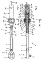
- the connecting member 5 is flattened by a pin 8 at the end of Length section 7 pivotally mounted in the tube 6.
- a tensioned Compression spring 10 incorporated in the form of a helical compression spring.
- the Compression spring 10 is based with its the Umschaltknarre 3 facing the end 11 at an acoustically perceptible, not illustrated in detail in the drawing Short-path release 12 coupled to the link 5 which is activated when the set torque value is reached.
- the other end 13 of the compression spring 10 is located at the bottom 14 of a pipe in the sixth slidable pot-shaped sleeve 15 made of steel.
- the jacket 16 of the sleeve 15 is in sliding contact with the inner surface 17 of the tube 6.
- the sleeve 15 summarizes one end 18 of a threaded spindle 19.
- the end 18 is determined by a transversely directed clamping pin 20 in the sleeve 15.
- the threaded spindle 19 passes through a facing away from the Umschaltknarre 3 End 9 of the tube 6 in this fixed by means of fixing pins 21 spindle nut 22.
- the other end 23 of the threaded spindle 19 sums in a blind hole 24 in the bottom 25 of a circumferentially ergonomically designed handle 26 an impact-resistant plastic.
- This end 23 of the threaded spindle 19 is by a threaded spindle 19 and the bottom 25 transversely interspersed Fixing pin 27 fixed.
- the handle 26 encloses the circumferentially smooth tube 6 relatively rotatable and sliding. At the end facing away from the bottom 25 has the Handle 26 circumferentially a cylindrical bearing surface 28, on which a clamping ring 29 is pushed with located on the periphery of the handle grooves 30.
- the surface of the tube 6 can be roughened to increase the static friction value ⁇ 0 .
- a suitable coating may be provided with a knurling in the form of a longitudinal, transverse or
- the clamping ring 29 is on the one hand by the over the bearing surface 28 for the Clamping ring 29 protruding portions 39 of the radial wedges 33 ( Figures 3 and 4) and on the other hand by an end-side gradation 40 in the clamping ring 29 and a radial collar 41 on the handle 26 out ( Figure 2).
- FIG. 2 Inner diameter extended frontal longitudinal section 42 is provided (FIG. 2), into which an adjustment sleeve 43 enclosing the tube 6 in a slidable manner used axially displaceable.
- the adjusting sleeve 43 is threaded through a threaded pin 44 connected to the handle 26, which in a radially extending Threaded hole 45 inserted in the wall 31 of the handle 26 is.
- the handle 26 serves both as an ergonomically designed handling element for force application as well as torque adjustment.
Landscapes
- Engineering & Computer Science (AREA)
- Mechanical Engineering (AREA)
- Details Of Spanners, Wrenches, And Screw Drivers And Accessories (AREA)
Abstract
Description
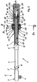
- Figur 1
- in der Draufsicht einen Drehmomentschlüssel;
- Figur 2
- den Drehmomentschlüssel der Figur 1 in der Seitenansicht, teil- weise im vertikalen Längsschnitt entlang der Linie II-II, in Richtung der Pfeile lla gesehen;
- Figur 3
- in vergrößertem Maßstab einen vertikalen Querschnitt durch die Darstellung der Figur 2 entlang der Linie III-III, in Richtung der Pfeile IIIa gesehen, während einer Verstellsituation und
- Figur 4
- ebenfalls in vergrößertem Maßstab einen vertikalen Querschnitt durch die Darstellung der Figur 2 entlang der Linie III-III, in Rich- tung der Pfeile IIIa gesehen, bei einem fixierten Handgriff.
- 1 -
- Drehmomentschlüssel
- 2 -
- Ende v. 1
- 3 -
- Umschaltknarre in 2
- 4 -
- Vierkantzapfen v. 3
- 5 -
- Verbindungsglied
- 6-
- Rohr
- 7 -
- Längenabschnitt v. 6
- 8-
- Zapfen
- 9 -
- Ende v. 6
- 10 -
- Druckfeder
- 11-
- Ende v. 10
- 12 -
- Kurzwegauslösung
- 13 -
- Ende v. 10
- 14 -
- Boden v. 15
- 15 -
- Hülse
- 16 -
- Mantel v. 15
- 17 -
- Innenoberfläche v. 6
- 18-
- Ende v. 19
- 19 -
- Gewindespindel
- 20-
- Spannstift
- 21 -
- Fixierstift
- 22 -
- Spindelmutter
- 23-
- Ende v. 19
- 24 -
- Sackloch in 25
- 25 -
- Boden v. 26
- 26 -
- Handgriff
- 27-
- Spannstift
- 28 -
- Lagerfläche an 26
- 29 -
- Spannring
- 30 -
- Griffnuten an 29
- 31 -
- Wand v. 26
- 32 -
- Aussparungen in 31
- 33-
- Radialkeile
- 34 -
- innere Stirnflächen v. 33
- 35 -
- Oberfläche v. 6
- 36 -
- äußere Stimflächen v. 33
- 37 -
- Exzenterflächen in 29
- 38 -
- Ausnehmungen in 29
- 39 -
- Abschnitte v. 33
- 40 -
- Abstufung in 29
- 41 -
- Radialkragen an 26
- 42 -
- Längenabschnitt in 26
- 43 -
- Einstellhülse
- 44 -
- Gewindestift
- 45 -
- Gewindebohrung in 31
- 46 -
- Radialbohrung in 29
- 47 -
- Stirnseite v. 43
- 48 -
- Skala
Claims (14)
- Schaft für einen Drehmomentschlüssel (1), der einen Handgriff (26) umfasst, welcher ein Ende (9) eines Rohrs (6) mit einer darin eingegliederten spannbaren Druckfeder (10) relativ verdrehbar und gleitschlüssig umschließt, wobei der Handgriff (26) eine eine endseitig im Rohr (6) fixierte Spindelmutter (22) durchsetzende und stirnseitig auf die Druckfeder (10) lastende, in einem Ende (25) des Handgriffs (26) befestigte zentrische Gewindespindel (19) aufweist sowie am anderen Ende von einem drehbaren Spannring (29) umgeben ist, über den sowie mindestens einen sich einerseits an der äußeren Oberfläche (35) des Rohrs (6) und andererseits an einer inneren Exzenterfläche (37) des Spannrings (29) abstützenden Radialkeil (33) der Handgriff (26) am Rohr (6) lagefixierbar ist.
- Schaft nach Anspruch 1, bei welchem die Gewindespindel (19) in ein Sackloch (24) im Boden (25) des Handgriffs (26) eingesetzt und durch einen die Gewindespindel (19) sowie den Boden (25) quer durchsetzenden Spannstift (27) im Handgriff (26) festgelegt ist.
- Schaft nach Anspruch 1 oder 2, bei welchem das der Druckfeder (10) benachbarte Ende (18) der Gewindespindel (19) in einer im Rohr (6) gleitfähigen topfförmigen Hülse (15) befestigt ist.
- Schaft nach einem der Ansprüche 1 bis 3, bei welchem der Radialkeil (33) in einer sich radial erstreckenden Aussparung (32) in der Wand (31) des Handgriffs (26) zwangsgeführt ist.
- Schaft nach einem der Ansprüche 1 bis 4, bei welchem der Spannring (29) durch einen über eine ihm zugeordnete Lagerfläche (28) am Handgriff (26) vorstehenden Abschnitt (39) des Radialkeils (33) geführt ist.
- Schaft nach einem der Ansprüche 1 bis 5, bei welchem die innere Stirnfläche (34) des Radialkeils (33) an die Krümmung der Oberfläche (35) des Rohrs (6) angepasst ist.
- Schaft nach einem der Ansprüche 1 bis 6, bei welchem die äußere Stirnfläche (36) des Radialkeils (33) an die Krümmung der Exzenterfläche (37) im Spannring (29) angeglichen ist.
- Schaft nach einem der Ansprüche 1 bis 7, bei welchem zwei Radialkeile (33) und zwei entsprechende Exzenterflächen (37) in 180° umfangsseitiger Versetzung vorgesehen sind.
- Schaft nach einem der Ansprüche 1 bis 8, bei welchem die Steigung jeder Exzenterfläche (37) im Bereich der Selbsthemmung liegt.
- Schaft nach einem der Ansprüche 1 bis 9, bei welchem im Bereich des Spannrings (29) eine das Rohr (6) gleitfähig umschließende Einstellhülse (43) dem Handgriff (26) axial lageveränderbar zugeordnet und an der Oberfläche (35) des Rohrs (6) eine Skala (48) mit Drehmomentangaben vorgesehen ist.
- Schaft nach Anspruch 10, bei welchem die Einstellhülse (43) in einen im Innendurchmesser erweiterten stirnseitigen Längenabschnitt (42) des Handgriffs (26) fasst und durch einen in der Wand (31) des Handgriffs (26) drehbar gelagerten Gewindestift (44) mit dem Handgriff (26) koppelbar ist.
- Schaft nach einem der Ansprüche 1 bis 11, bei welchem der Handgriff (26), der Spannring (29), jeder Radialkeil (33) und die Einstellhülse (43) aus einem schlagfesten Kunststoff bestehen.
- Schaft nach einem der Ansprüche 1 bis 12, bei welchem die Wand (31) und der Boden (25) des Handgriffs (26) einstückig ausgebildet sind.
- Schaft nach einem der Ansprüche 1 bis 13, bei welchem der Haftreibungswert µ0 im Kontaktbereich des Rohrs (6) mit der Stirnfläche (34) eines Radialkeils (33) größer als in den umfangsseitig benachbarten Bereichen ist.
Applications Claiming Priority (2)
| Application Number | Priority Date | Filing Date | Title |
|---|---|---|---|
| DE20119801U | 2001-12-06 | ||
| DE20119801U DE20119801U1 (de) | 2001-12-06 | 2001-12-06 | Schaft für einen Drehmomentschlüssel |
Publications (3)
| Publication Number | Publication Date |
|---|---|
| EP1317997A2 true EP1317997A2 (de) | 2003-06-11 |
| EP1317997A3 EP1317997A3 (de) | 2006-09-13 |
| EP1317997B1 EP1317997B1 (de) | 2009-12-09 |
Family
ID=7964863
Family Applications (1)
| Application Number | Title | Priority Date | Filing Date |
|---|---|---|---|
| EP02025143A Expired - Lifetime EP1317997B1 (de) | 2001-12-06 | 2002-11-09 | Schaft für einen Drehmomentschlüssel |
Country Status (4)
| Country | Link |
|---|---|
| EP (1) | EP1317997B1 (de) |
| AT (1) | ATE451201T1 (de) |
| DE (2) | DE20119801U1 (de) |
| ES (1) | ES2336894T3 (de) |
Cited By (2)
| Publication number | Priority date | Publication date | Assignee | Title |
|---|---|---|---|---|
| EP1502708A1 (de) * | 2003-07-31 | 2005-02-02 | Hazet-Werk Hermann Zerver GmbH & Co. KG | Drehmomentschlüssel |
| US20230202006A1 (en) * | 2021-12-27 | 2023-06-29 | Shanghai UB Machinery Co, Ltd. | Magnetically locking mechanism of a torque wrench |
Families Citing this family (1)
| Publication number | Priority date | Publication date | Assignee | Title |
|---|---|---|---|---|
| TWI736398B (zh) * | 2020-08-21 | 2021-08-11 | 和嘉興精密股份有限公司 | 扭力結構 |
Citations (3)
| Publication number | Priority date | Publication date | Assignee | Title |
|---|---|---|---|---|
| US2667800A (en) | 1951-02-12 | 1954-02-02 | George C Jenkins | Adjustable break-through torque wrench |
| EP0697268B1 (de) | 1994-08-16 | 1998-09-09 | Hazet-Werk Hermann Zerver GmbH & Co. KG | Vorrichtung zur lösbaren Festlegung eines zu Verstellzwecken verdrehbaren Handgriffes |
| DE20114265U1 (de) | 2001-08-29 | 2001-11-15 | Hazet-Werk Hermann Zerver GmbH & Co. KG, 42857 Remscheid | Drehmomentschlüssel |
Family Cites Families (3)
| Publication number | Priority date | Publication date | Assignee | Title |
|---|---|---|---|---|
| US2704472A (en) * | 1955-03-22 | Mined torque release means | ||
| US5129293A (en) * | 1991-06-10 | 1992-07-14 | Precision Instruments, Inc. | Torque control mechanism for wrenches and the like |
| US5662012A (en) * | 1995-11-07 | 1997-09-02 | Consolidated Devices, Inc. | Torque wrench structure |
-
2001
- 2001-12-06 DE DE20119801U patent/DE20119801U1/de not_active Expired - Lifetime
-
2002
- 2002-11-09 AT AT02025143T patent/ATE451201T1/de active
- 2002-11-09 ES ES02025143T patent/ES2336894T3/es not_active Expired - Lifetime
- 2002-11-09 DE DE50214065T patent/DE50214065D1/de not_active Expired - Lifetime
- 2002-11-09 EP EP02025143A patent/EP1317997B1/de not_active Expired - Lifetime
Patent Citations (3)
| Publication number | Priority date | Publication date | Assignee | Title |
|---|---|---|---|---|
| US2667800A (en) | 1951-02-12 | 1954-02-02 | George C Jenkins | Adjustable break-through torque wrench |
| EP0697268B1 (de) | 1994-08-16 | 1998-09-09 | Hazet-Werk Hermann Zerver GmbH & Co. KG | Vorrichtung zur lösbaren Festlegung eines zu Verstellzwecken verdrehbaren Handgriffes |
| DE20114265U1 (de) | 2001-08-29 | 2001-11-15 | Hazet-Werk Hermann Zerver GmbH & Co. KG, 42857 Remscheid | Drehmomentschlüssel |
Cited By (2)
| Publication number | Priority date | Publication date | Assignee | Title |
|---|---|---|---|---|
| EP1502708A1 (de) * | 2003-07-31 | 2005-02-02 | Hazet-Werk Hermann Zerver GmbH & Co. KG | Drehmomentschlüssel |
| US20230202006A1 (en) * | 2021-12-27 | 2023-06-29 | Shanghai UB Machinery Co, Ltd. | Magnetically locking mechanism of a torque wrench |
Also Published As
| Publication number | Publication date |
|---|---|
| DE50214065D1 (de) | 2010-01-21 |
| ATE451201T1 (de) | 2009-12-15 |
| DE20119801U1 (de) | 2002-02-14 |
| EP1317997A3 (de) | 2006-09-13 |
| EP1317997B1 (de) | 2009-12-09 |
| ES2336894T3 (es) | 2010-04-19 |
Similar Documents
| Publication | Publication Date | Title |
|---|---|---|
| WO2011003397A1 (de) | Spannfutter für ein werkzeug | |
| DE102010014322A1 (de) | Werkzeugkopf für ein rotierendes Werkzeug | |
| DE3139140C2 (de) | Vorrichtung zur Drehmomentbegrenzung | |
| DE69008758T2 (de) | Werkzeugkoppelung zwischen einem Werkzeughalter und einer Maschinenspindel. | |
| EP0275441A1 (de) | Spannvorrichtung | |
| DE102006055516A1 (de) | Zusatzhandgriff für eine Handwerkzeugmaschine mit Schnellverstellung durch zwei Gewinde | |
| DE2908422C2 (de) | Hon- oder Läppkopf | |
| EP1317997A2 (de) | Schaft für einen Drehmomentschlüssel | |
| DE4437508B4 (de) | Arretierelement | |
| AT523901B1 (de) | Selbstsichernder Vorspannring für Federbeine | |
| DE68910146T2 (de) | Werkzeughalter für ein Werkzeug mit Schaft. | |
| DE3604454C1 (de) | Druckaufbaudorn zum druckdichten Befestigen eines Rohres in einer OEffnung eines Rohrbodens | |
| DE4335259A1 (de) | Spannvorrichtung für mindestens eine auf einem Schaft festzulegende Wickelhülse o. dgl. | |
| EP0697268B1 (de) | Vorrichtung zur lösbaren Festlegung eines zu Verstellzwecken verdrehbaren Handgriffes | |
| CH660324A5 (de) | Spannvorrichtung fuer verzahnte werkstuecke. | |
| EP3807051A1 (de) | Drehmomentbegrenzungseinrichtung und verfahren zu dessen kalibrierung | |
| EP0325728B1 (de) | Spannfutter für Gewindeschäfte | |
| DE29914202U1 (de) | Nietsetzwerkzeug mit Hubeinstellung | |
| EP1418111B1 (de) | Auf einem Mantelrohr befestigbares Lenksäule-Nabemodul | |
| DE10052578A1 (de) | Verbindungselement | |
| DE3933913A1 (de) | Drehmomentschluessel | |
| EP1122032A2 (de) | Spannfutter für Schaftenden von Werkzeugseinsatzstücken, insbesondere Schraubendreherbits | |
| DE20003929U1 (de) | Befestigungskörper für einen Tür- und/oder Fensterbeschlag | |
| DE29912708U1 (de) | Schraubwerkzeug zum Eindrehen von Gewindebolzen | |
| DE202019104457U1 (de) | Haltergehäuse für einen Türfeststeller sowie Türfeststeller |
Legal Events
| Date | Code | Title | Description |
|---|---|---|---|
| PUAI | Public reference made under article 153(3) epc to a published international application that has entered the european phase |
Free format text: ORIGINAL CODE: 0009012 |
|
| AK | Designated contracting states |
Designated state(s): AT BE BG CH CY CZ DE DK EE ES FI FR GB GR IE IT LI LU MC NL PT SE SK TR |
|
| AX | Request for extension of the european patent |
Extension state: AL LT LV MK RO SI |
|
| PUAL | Search report despatched |
Free format text: ORIGINAL CODE: 0009013 |
|
| AK | Designated contracting states |
Kind code of ref document: A3 Designated state(s): AT BE BG CH CY CZ DE DK EE ES FI FR GB GR IE IT LI LU MC NL PT SE SK TR |
|
| AX | Request for extension of the european patent |
Extension state: AL LT LV MK RO SI |
|
| 17P | Request for examination filed |
Effective date: 20060824 |
|
| AKX | Designation fees paid |
Designated state(s): AT BE BG CH CY CZ DE DK EE ES FI FR GB GR IE IT LI LU MC NL PT SE SK TR |
|
| 17Q | First examination report despatched |
Effective date: 20081107 |
|
| GRAP | Despatch of communication of intention to grant a patent |
Free format text: ORIGINAL CODE: EPIDOSNIGR1 |
|
| GRAS | Grant fee paid |
Free format text: ORIGINAL CODE: EPIDOSNIGR3 |
|
| GRAA | (expected) grant |
Free format text: ORIGINAL CODE: 0009210 |
|
| AK | Designated contracting states |
Kind code of ref document: B1 Designated state(s): AT BE BG CH CY CZ DE DK EE ES FI FR GB GR IE IT LI LU MC NL PT SE SK TR |
|
| REG | Reference to a national code |
Ref country code: GB Ref legal event code: FG4D Free format text: NOT ENGLISH |
|
| REG | Reference to a national code |
Ref country code: CH Ref legal event code: EP |
|
| REG | Reference to a national code |
Ref country code: IE Ref legal event code: FG4D |
|
| REF | Corresponds to: |
Ref document number: 50214065 Country of ref document: DE Date of ref document: 20100121 Kind code of ref document: P |
|
| REG | Reference to a national code |
Ref country code: CH Ref legal event code: NV Representative=s name: PATENTANWAELTE SCHAAD, BALASS, MENZL & PARTNER AG |
|
| REG | Reference to a national code |
Ref country code: ES Ref legal event code: FG2A Ref document number: 2336894 Country of ref document: ES Kind code of ref document: T3 |
|
| PG25 | Lapsed in a contracting state [announced via postgrant information from national office to epo] |
Ref country code: FI Free format text: LAPSE BECAUSE OF FAILURE TO SUBMIT A TRANSLATION OF THE DESCRIPTION OR TO PAY THE FEE WITHIN THE PRESCRIBED TIME-LIMIT Effective date: 20091209 Ref country code: SE Free format text: LAPSE BECAUSE OF FAILURE TO SUBMIT A TRANSLATION OF THE DESCRIPTION OR TO PAY THE FEE WITHIN THE PRESCRIBED TIME-LIMIT Effective date: 20091209 |
|
| REG | Reference to a national code |
Ref country code: IE Ref legal event code: FD4D |
|
| PG25 | Lapsed in a contracting state [announced via postgrant information from national office to epo] |
Ref country code: PT Free format text: LAPSE BECAUSE OF FAILURE TO SUBMIT A TRANSLATION OF THE DESCRIPTION OR TO PAY THE FEE WITHIN THE PRESCRIBED TIME-LIMIT Effective date: 20100409 Ref country code: EE Free format text: LAPSE BECAUSE OF FAILURE TO SUBMIT A TRANSLATION OF THE DESCRIPTION OR TO PAY THE FEE WITHIN THE PRESCRIBED TIME-LIMIT Effective date: 20091209 Ref country code: IE Free format text: LAPSE BECAUSE OF FAILURE TO SUBMIT A TRANSLATION OF THE DESCRIPTION OR TO PAY THE FEE WITHIN THE PRESCRIBED TIME-LIMIT Effective date: 20091209 Ref country code: BG Free format text: LAPSE BECAUSE OF FAILURE TO SUBMIT A TRANSLATION OF THE DESCRIPTION OR TO PAY THE FEE WITHIN THE PRESCRIBED TIME-LIMIT Effective date: 20100309 |
|
| PG25 | Lapsed in a contracting state [announced via postgrant information from national office to epo] |
Ref country code: CZ Free format text: LAPSE BECAUSE OF FAILURE TO SUBMIT A TRANSLATION OF THE DESCRIPTION OR TO PAY THE FEE WITHIN THE PRESCRIBED TIME-LIMIT Effective date: 20091209 Ref country code: SK Free format text: LAPSE BECAUSE OF FAILURE TO SUBMIT A TRANSLATION OF THE DESCRIPTION OR TO PAY THE FEE WITHIN THE PRESCRIBED TIME-LIMIT Effective date: 20091209 |
|
| PLBE | No opposition filed within time limit |
Free format text: ORIGINAL CODE: 0009261 |
|
| STAA | Information on the status of an ep patent application or granted ep patent |
Free format text: STATUS: NO OPPOSITION FILED WITHIN TIME LIMIT |
|
| PG25 | Lapsed in a contracting state [announced via postgrant information from national office to epo] |
Ref country code: CY Free format text: LAPSE BECAUSE OF FAILURE TO SUBMIT A TRANSLATION OF THE DESCRIPTION OR TO PAY THE FEE WITHIN THE PRESCRIBED TIME-LIMIT Effective date: 20091209 Ref country code: GR Free format text: LAPSE BECAUSE OF FAILURE TO SUBMIT A TRANSLATION OF THE DESCRIPTION OR TO PAY THE FEE WITHIN THE PRESCRIBED TIME-LIMIT Effective date: 20100310 |
|
| 26N | No opposition filed |
Effective date: 20100910 |
|
| PG25 | Lapsed in a contracting state [announced via postgrant information from national office to epo] |
Ref country code: DK Free format text: LAPSE BECAUSE OF FAILURE TO SUBMIT A TRANSLATION OF THE DESCRIPTION OR TO PAY THE FEE WITHIN THE PRESCRIBED TIME-LIMIT Effective date: 20091209 |
|
| PG25 | Lapsed in a contracting state [announced via postgrant information from national office to epo] |
Ref country code: MC Free format text: LAPSE BECAUSE OF NON-PAYMENT OF DUE FEES Effective date: 20101130 |
|
| GBPC | Gb: european patent ceased through non-payment of renewal fee |
Effective date: 20101109 |
|
| PG25 | Lapsed in a contracting state [announced via postgrant information from national office to epo] |
Ref country code: GB Free format text: LAPSE BECAUSE OF NON-PAYMENT OF DUE FEES Effective date: 20101109 |
|
| PG25 | Lapsed in a contracting state [announced via postgrant information from national office to epo] |
Ref country code: TR Free format text: LAPSE BECAUSE OF FAILURE TO SUBMIT A TRANSLATION OF THE DESCRIPTION OR TO PAY THE FEE WITHIN THE PRESCRIBED TIME-LIMIT Effective date: 20091209 |
|
| REG | Reference to a national code |
Ref country code: FR Ref legal event code: PLFP Year of fee payment: 14 |
|
| REG | Reference to a national code |
Ref country code: FR Ref legal event code: PLFP Year of fee payment: 15 |
|
| REG | Reference to a national code |
Ref country code: FR Ref legal event code: PLFP Year of fee payment: 16 |
|
| PGFP | Annual fee paid to national office [announced via postgrant information from national office to epo] |
Ref country code: LU Payment date: 20171120 Year of fee payment: 16 |
|
| PGFP | Annual fee paid to national office [announced via postgrant information from national office to epo] |
Ref country code: DE Payment date: 20171128 Year of fee payment: 16 Ref country code: NL Payment date: 20171120 Year of fee payment: 16 Ref country code: FR Payment date: 20171121 Year of fee payment: 16 |
|
| PGFP | Annual fee paid to national office [announced via postgrant information from national office to epo] |
Ref country code: IT Payment date: 20171124 Year of fee payment: 16 Ref country code: ES Payment date: 20171220 Year of fee payment: 16 Ref country code: AT Payment date: 20171121 Year of fee payment: 16 Ref country code: BE Payment date: 20171120 Year of fee payment: 16 Ref country code: CH Payment date: 20171120 Year of fee payment: 16 |
|
| REG | Reference to a national code |
Ref country code: DE Ref legal event code: R119 Ref document number: 50214065 Country of ref document: DE |
|
| REG | Reference to a national code |
Ref country code: CH Ref legal event code: PL |
|
| REG | Reference to a national code |
Ref country code: NL Ref legal event code: MM Effective date: 20181201 |
|
| REG | Reference to a national code |
Ref country code: AT Ref legal event code: MM01 Ref document number: 451201 Country of ref document: AT Kind code of ref document: T Effective date: 20181109 |
|
| PG25 | Lapsed in a contracting state [announced via postgrant information from national office to epo] |
Ref country code: LU Free format text: LAPSE BECAUSE OF NON-PAYMENT OF DUE FEES Effective date: 20181109 |
|
| REG | Reference to a national code |
Ref country code: BE Ref legal event code: MM Effective date: 20181130 |
|
| PG25 | Lapsed in a contracting state [announced via postgrant information from national office to epo] |
Ref country code: LI Free format text: LAPSE BECAUSE OF NON-PAYMENT OF DUE FEES Effective date: 20181130 Ref country code: NL Free format text: LAPSE BECAUSE OF NON-PAYMENT OF DUE FEES Effective date: 20181201 Ref country code: CH Free format text: LAPSE BECAUSE OF NON-PAYMENT OF DUE FEES Effective date: 20181130 |
|
| PG25 | Lapsed in a contracting state [announced via postgrant information from national office to epo] |
Ref country code: IT Free format text: LAPSE BECAUSE OF NON-PAYMENT OF DUE FEES Effective date: 20181109 Ref country code: FR Free format text: LAPSE BECAUSE OF NON-PAYMENT OF DUE FEES Effective date: 20181130 Ref country code: AT Free format text: LAPSE BECAUSE OF NON-PAYMENT OF DUE FEES Effective date: 20181109 Ref country code: DE Free format text: LAPSE BECAUSE OF NON-PAYMENT OF DUE FEES Effective date: 20190601 |
|
| PG25 | Lapsed in a contracting state [announced via postgrant information from national office to epo] |
Ref country code: BE Free format text: LAPSE BECAUSE OF NON-PAYMENT OF DUE FEES Effective date: 20181130 |
|
| REG | Reference to a national code |
Ref country code: ES Ref legal event code: FD2A Effective date: 20200102 |
|
| PG25 | Lapsed in a contracting state [announced via postgrant information from national office to epo] |
Ref country code: ES Free format text: LAPSE BECAUSE OF NON-PAYMENT OF DUE FEES Effective date: 20181110 |