EP1318324A2 - Ensemble amortisseur d'un véhicule - Google Patents
Ensemble amortisseur d'un véhicule Download PDFInfo
- Publication number
- EP1318324A2 EP1318324A2 EP02079832A EP02079832A EP1318324A2 EP 1318324 A2 EP1318324 A2 EP 1318324A2 EP 02079832 A EP02079832 A EP 02079832A EP 02079832 A EP02079832 A EP 02079832A EP 1318324 A2 EP1318324 A2 EP 1318324A2
- Authority
- EP
- European Patent Office
- Prior art keywords
- piston
- housing
- curved portion
- fluid
- damper assembly
- Prior art date
- Legal status (The legal status is an assumption and is not a legal conclusion. Google has not performed a legal analysis and makes no representation as to the accuracy of the status listed.)
- Withdrawn
Links
- 239000012530 fluid Substances 0.000 claims abstract description 39
- 238000000034 method Methods 0.000 claims abstract description 9
- 239000000725 suspension Substances 0.000 description 7
- 229910001209 Low-carbon steel Inorganic materials 0.000 description 2
- PXHVJJICTQNCMI-UHFFFAOYSA-N Nickel Chemical compound [Ni] PXHVJJICTQNCMI-UHFFFAOYSA-N 0.000 description 2
- 239000000463 material Substances 0.000 description 2
- 238000004904 shortening Methods 0.000 description 2
- 229910000831 Steel Inorganic materials 0.000 description 1
- 239000006096 absorbing agent Substances 0.000 description 1
- 229910052782 aluminium Inorganic materials 0.000 description 1
- XAGFODPZIPBFFR-UHFFFAOYSA-N aluminium Chemical compound [Al] XAGFODPZIPBFFR-UHFFFAOYSA-N 0.000 description 1
- 239000002131 composite material Substances 0.000 description 1
- 150000001875 compounds Chemical class 0.000 description 1
- 238000013016 damping Methods 0.000 description 1
- 230000000694 effects Effects 0.000 description 1
- 239000013013 elastic material Substances 0.000 description 1
- 230000005674 electromagnetic induction Effects 0.000 description 1
- 229910052751 metal Inorganic materials 0.000 description 1
- 239000002184 metal Substances 0.000 description 1
- 229910001092 metal group alloy Inorganic materials 0.000 description 1
- 238000012986 modification Methods 0.000 description 1
- 230000004048 modification Effects 0.000 description 1
- 229910052759 nickel Inorganic materials 0.000 description 1
- 238000007747 plating Methods 0.000 description 1
- 229920002635 polyurethane Polymers 0.000 description 1
- 239000004814 polyurethane Substances 0.000 description 1
- 230000035939 shock Effects 0.000 description 1
- 239000010959 steel Substances 0.000 description 1
Images


Classifications
-
- F—MECHANICAL ENGINEERING; LIGHTING; HEATING; WEAPONS; BLASTING
- F16—ENGINEERING ELEMENTS AND UNITS; GENERAL MEASURES FOR PRODUCING AND MAINTAINING EFFECTIVE FUNCTIONING OF MACHINES OR INSTALLATIONS; THERMAL INSULATION IN GENERAL
- F16F—SPRINGS; SHOCK-ABSORBERS; MEANS FOR DAMPING VIBRATION
- F16F9/00—Springs, vibration-dampers, shock-absorbers, or similarly-constructed movement-dampers using a fluid or the equivalent as damping medium
- F16F9/32—Details
- F16F9/3207—Constructional features
- F16F9/3214—Constructional features of pistons
-
- F—MECHANICAL ENGINEERING; LIGHTING; HEATING; WEAPONS; BLASTING
- F16—ENGINEERING ELEMENTS AND UNITS; GENERAL MEASURES FOR PRODUCING AND MAINTAINING EFFECTIVE FUNCTIONING OF MACHINES OR INSTALLATIONS; THERMAL INSULATION IN GENERAL
- F16F—SPRINGS; SHOCK-ABSORBERS; MEANS FOR DAMPING VIBRATION
- F16F9/00—Springs, vibration-dampers, shock-absorbers, or similarly-constructed movement-dampers using a fluid or the equivalent as damping medium
- F16F9/32—Details
- F16F9/53—Means for adjusting damping characteristics by varying fluid viscosity, e.g. electromagnetically
- F16F9/535—Magnetorheological [MR] fluid dampers
Definitions
- the present invention relates generally to vehicular suspension systems. More particularly, the invention relates to a vehicle damper assembly and method for reducing binding contact.
- Linear suspension dampers such as shock absorbers and McPherson struts, may include a rod and piston moving within a housing. Suspension movements transmitted to the rod and piston may be dampened by a fluid carried within the housing. As the fluid flows between a piston outer surface and housing inner surface, a dampening friction force is generated. To ensure consistent and reliable damper performance, several design factors may be considered.
- damper design One consideration in damper design relates to friction and wear.
- Some current damper designs include a cylindrical piston sized to closely fit within a cylindrical housing. During damper operation, the piston may repeatedly contact the inner surface of the housing resulting in excessive wear.
- a small fluid-filled gap may be provided between the piston outer surface and housing inner surface to reduce friction and wear.
- the fluid-filled gap acts as a hydrodynamic "bearing" between the piston and housing engagement surfaces. Control of the fit and fluid flow gap size between the piston and housing is important in maintaining adequate hydrodynamic bearing. For example, sufficient narrowing of the flow gap size may compromise hydrodynamic bearing and result in excessive wear. Accordingly, it would be desirable for a damper design to provide adequate hydrodynamic bearing to minimize friction and wear.
- damper assembly misalignment Another consideration in damper design relates to damper assembly misalignment.
- damper assembly inherent process variation may result in a misalignment between the rod and outside surface of the piston.
- the fit and fluid gap between the piston and housing provides hydrodynamic bearing minimizing friction and wear.
- Misalignment of the parts may compromise hydrodynamic bearing resulting in repeated contact between surfaces. The contact may produce excessive frictional wear thereby shortening damper lifespan. If the misalignment is sufficient, the piston may not be able to freely slide within the tube due to the binding contact. The binding contact may cause the piston to "seize" within the housing. Accordingly, it would be desirable for a damper design to reduce the consequences associated with damper assembly misalignment.
- a vehicle damper assembly including a housing including a fluid carried therein, a piston slidably carried in the housing, and a rod operably attached to the piston.
- the piston includes a curved portion positioned adjacent a housing inner surface.
- the fluid may be magnetorheological fluid.
- the curved portion may include a longitudinal radius and/or form a barrel shape. The curved portion may contact the housing inner surface during operation of the vehicle damper assembly.
- the curved portion includes piston means for reducing binding contact and/or means for maintaining hydrodynamic bearing between the piston and the housing inner surface.
- a vehicle damper assembly including housing means for carrying a fluid, piston means for reducing binding contact with the housing means, and rod means for moving the piston means.
- the fluid may be magnetorheological fluid.
- the vehicle damper assembly may further include means for maintaining hydrodynamic bearing between the piston means and the housing means.
- a longitudinal radius is determined for a piston based on a housing inner surface.
- the piston is formed with a curved portion based on the longitudinal radius.
- the curved portion is positioned adjacent the housing inner surface. Hydrodynamic bearing may be maintained between the piston and the housing inner surface.
- FIG. 1 is an exaggerated view (i.e., not drawn to scale) of a prior art vehicle damper assembly shown generally by numeral (10).
- Vehicle damper assembly (10) may include a housing (11) including a fluid (12) carried therein, a piston (13) slidably carried in housing (11), and a rod (14) operably attached to piston (13).
- piston (13) may move within housing (11) in response to vehicle suspension movements transmitted through rod (14). Piston (13) movements may force fluid (12) between at least one opening (15) formed between a piston surface (16) and housing inner surface (17). Vehicle suspension movements may be dampened by fluid frictional forces generated against piston (13) movements.
- Vehicle damper assembly (10) is shown in a misaligned state (i.e., piston 13 and rod 14 do not share a common central axis 18).
- the misalignment may be due to variation in the assembly process. Misalignment may reduce opening (15) size and compromise hydrodynamic bearing resulting in repeated contact between surfaces (16, 17). The contact may produce excessive frictional wear thereby shortening damper assembly (10) lifespan. Misalignment may also promote binding contact between surfaces (16, 17). Piston (13), having a cylindrical shape, may experience binding contact, especially when misaligned. The binding contact may occur where piston surface (16) is angular in shape, such as at a corner portion 19. Excessive binding contact may cause piston (13) to "seize" within housing (11).
- FIG. 2 is an exaggerated view of a vehicle damper assembly (20) made in accordance with the present invention.
- Vehicle damper assembly (20) may include a housing (21) including a fluid (22) carried therein, a piston (23) slidably carried in housing (21), and a rod (24) operably attached to piston (23).
- Piston (23) may include at least one curved portion (26) positioned adjacent a housing inner surface (27).
- curved portion is defined as a curved surface that projects in an orthogonal direction from a piston central axis.
- piston (23) may move within housing (21) in response to vehicle suspension movements transmitted through rod (24). Piston (23) movements may force fluid (22) between at least one opening (25) formed by piston curved portion (26) and housing inner surface (27). Vehicle suspension movements may be dampened by fluid frictional forces generated against piston (23) movements.
- Vehicle damper assembly (20) is shown in a misaligned state.
- Curved portion (26) may contact housing inner surface (27) during vehicle damper assembly (20) operation, especially when the vehicle damper assembly (20) is misaligned.
- Curved portion (26) may reduce the consequences of vehicle damper assembly (20) misalignment.
- curved portion (26) may provide means for maintaining hydrodynamic bearing between the curved portion (26) and housing inner surface (27).
- curved portion (26) may reduce contact between housing (21) and piston (23) thereby reducing damper assembly (20) wear.
- Curved portion (26) may also provide means for reducing binding contact of surfaces (26), (27).
- a curved surface may be less likely to bind than an angular surface. As such, curved portion (26) may prevent piston (23) from seizing within housing (21).
- Binding contact may be reduced by forming piston (23) with curved portion(s) (26) based on a longitudinal radius (28).
- the longitudinal radius (28) may be determined for a particular piston by considering the housing inner surface (27).
- longitudinal radius (28) may be about 5 to 15 times a housing inner surface diameter (29).
- the longitudinal radius (28) may be about 10 times housing inner diameter (29).
- a longitudinal radius (28) greater than 15 times inner surface diameter (29) may not provide enough curvature to reduce binding contact.
- a longitudinal radius (28) less than 5 times inner surface diameter (29) may provide excessive curvature thereby compromising hydrodynamic bearing.
- the determined longitudinal radius (28) may then be partially rotated about a central point forming an arc or parabola (as shown by double arrow). Curved portion (26) may be based on the shape of the arc or parabola.
- the longitudinal radius (28) may form a piston barrel shape (i.e., a cylindrical shape having a variable diameter, the diameter being wider near a middle portion than end portions).
- the piston barrel shape would include a generally cylindrical shape having bent sides based on the arc or parabolic shapes.
- the barrel shape may provide an acceptable shape for maintaining hydrodynamic bearing by providing a relatively long gap of effective engagement (i.e., area where curved portion 26 and housing inner surface 27 are substantially parallel and separated by a relatively small gap of fluid 22).
- a spherical shape may not provide as acceptable hydrodynamic bearing due to its relatively shorter gap of effective engagement.
- the curved portion (26) need not be based on a simple arc or parabola.
- curved portion (26) may be based on numerous simple and/or compound curved surfaces while providing the advantages associated with the present invention.
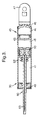
- FIG. 3 & 4 wherein like reference numerals refer to like elements, are perspective views of a vehicle damper assembly (30) made in accordance with the present invention.
- vehicle damper assembly (30) may include a number of alternate damper designs.
- vehicle damper assembly (30) is shown and described as a linear acting fluid damper employing magnetic tuning with a magnetorheological fluid to effect desired damping level.
- Vehicle damper assembly (30) includes a housing (40) including a fluid (41) carried therein, a piston (50) slidably carried in housing (40), and a rod (60) operably attached to piston (50).
- the housing (40), piston (50), and rod (60) may be formed from a number of sufficiently rigid materials such as steel, aluminum, metal, metal alloy, composites, and the like.
- Fluid (41) may be any number of fluids used for providing dampening characteristics.
- piston (50) may be formed from low-carbon steel with nickel plating and fluid (41) may be magnetorheological fluid. Low-carbon steel may provide electro-magnetic induction properties compatible with magnetorheological fluid use.
- piston (50) includes at least one curved portion (51) positioned adjacent a housing inner surface (42).
- curved portion (51) extends from piston (50) surface outwardly for a profile distance (52) and length (53).
- the profile distance (52) and length (53) may be based on a longitudinal radius to maintain hydrodynamic bearing and reduce binding contact.
- piston (50) may include curved portion (51) forming a barrel shape.
- the barrel shape may provide a relatively long gap of effective engagement (54) allowing fluid (41) to flow during piston (50) movement.
- the barrel shape may reduce binding contact between piston (50) and housing inner surface (42).
- Piston (50) may include one or more wires (55) for providing electrical current to one or more coils (56). Fluid (41) may flow through one or more ports (57) formed through piston (50). The coils (56) provide means for modulating the viscosity of magnetorheological fluid (41) as it flows through ports (57) thereby effecting desired dampening level. Piston (50) may be attached to rod (60) with one or more ring clips (61) or other attachment means.
- rod (60) may include one or more bumpers (62) to limit piston (50) range of motion and "quiet" piston (50) contact with a first housing end portion (43).
- Bumpers (62) may be formed from an elastic material compatible with fluid (41), such as a polyurethane material.
- Housing (40) may include a gas (44) contained by a cap (45) to provide a force against piston (50) as it travels toward a second housing end portion (46).
- Housing (40) and rod (60) may include a wheel assembly attachment means (47) and a vehicle chassis attachment means (63), respectively.
- the damper assembly configuration, and method for determining a longitudinal radius are not limited to any particular design or sequence.
- the curved portion shape, location, and number, the damper design, and longitudinal radius may vary without limiting the utility of the invention.
Landscapes
- Engineering & Computer Science (AREA)
- General Engineering & Computer Science (AREA)
- Mechanical Engineering (AREA)
- Physics & Mathematics (AREA)
- Electromagnetism (AREA)
- Fluid-Damping Devices (AREA)
- Vehicle Body Suspensions (AREA)
Applications Claiming Priority (2)
| Application Number | Priority Date | Filing Date | Title |
|---|---|---|---|
| US10/011,694 US20030106752A1 (en) | 2001-12-07 | 2001-12-07 | Vehicle damper assembly and method for reducing binding contact |
| US11694 | 2001-12-07 |
Publications (2)
| Publication Number | Publication Date |
|---|---|
| EP1318324A2 true EP1318324A2 (fr) | 2003-06-11 |
| EP1318324A3 EP1318324A3 (fr) | 2003-12-17 |
Family
ID=21751580
Family Applications (1)
| Application Number | Title | Priority Date | Filing Date |
|---|---|---|---|
| EP02079832A Withdrawn EP1318324A3 (fr) | 2001-12-07 | 2002-11-20 | Ensemble amortisseur d'un véhicule |
Country Status (2)
| Country | Link |
|---|---|
| US (1) | US20030106752A1 (fr) |
| EP (1) | EP1318324A3 (fr) |
Families Citing this family (2)
| Publication number | Priority date | Publication date | Assignee | Title |
|---|---|---|---|---|
| US6612409B2 (en) * | 2001-12-27 | 2003-09-02 | Delphi Technologies, Inc. | Magneotorheological piston and damper |
| CN118664440B (zh) * | 2024-06-28 | 2025-10-03 | 中国工程物理研究院激光聚变研究中心 | 一种复杂曲面磁流变加工误差收敛评估方法 |
Family Cites Families (7)
| Publication number | Priority date | Publication date | Assignee | Title |
|---|---|---|---|---|
| DE195214C (fr) * | 1921-07-13 | |||
| FR658276A (fr) * | 1928-05-07 | 1929-06-03 | Frein amortisseur à centrage constant pour instruments de pesage automatiques et semi-automatiques | |
| JPS6088222A (ja) * | 1983-10-21 | 1985-05-18 | Daido Metal Kogyo Kk | 複合摺動体 |
| FR2579283B1 (fr) * | 1985-03-19 | 1989-06-16 | Renault | Amortisseur de vibrations electromagnetique |
| JPS63152744A (ja) * | 1986-12-16 | 1988-06-25 | Showa Electric Wire & Cable Co Ltd | 精密除振台 |
| ES2124111B1 (es) * | 1994-11-15 | 1999-08-16 | Sintermetal Sa | Conjunto de embolo y guia de su vastago para amortiguadores hidraulicos. |
| US6311810B1 (en) * | 1999-10-21 | 2001-11-06 | Delphi Technologies, Inc. | Magnetorheological fluid damper |
-
2001
- 2001-12-07 US US10/011,694 patent/US20030106752A1/en not_active Abandoned
-
2002
- 2002-11-20 EP EP02079832A patent/EP1318324A3/fr not_active Withdrawn
Non-Patent Citations (1)
| Title |
|---|
| None |
Also Published As
| Publication number | Publication date |
|---|---|
| US20030106752A1 (en) | 2003-06-12 |
| EP1318324A3 (fr) | 2003-12-17 |
Similar Documents
| Publication | Publication Date | Title |
|---|---|---|
| US6547044B2 (en) | Magneto-rheological damper with ferromagnetic housing insert | |
| US6336535B1 (en) | Magneto-rheological damper with dual flux ring spacer | |
| US6874603B2 (en) | Magnetorheological piston and damper assembly | |
| US6053291A (en) | Damper of a type with a variable damping force | |
| US6382369B1 (en) | Magneto-rheological fluid damper with an external coil | |
| US6840358B2 (en) | Floating rod guide for monotube strut | |
| US6497309B1 (en) | Magneto-rheological damper with an external coil | |
| US6390258B1 (en) | Floating rod guide for monotube strut | |
| US8333270B2 (en) | Floating piston valve of amplitude selective shock absorber | |
| US6637560B2 (en) | Vehicle damper assembly and method of modulating fluid flow | |
| KR100892999B1 (ko) | 연속 감쇠력 가변형 댐퍼의 피스톤밸브 어셈블리 | |
| US20040118646A1 (en) | Magnetorheological damper assembly and piston | |
| CN105637252A (zh) | 用于控制液压装置中的可变负载的系统 | |
| US5385136A (en) | Impulse stabilizer capable of asymmetrical response | |
| US5535862A (en) | Suspension strut with quiet rebound stop | |
| US20020130002A1 (en) | Gas cup seal for magneto-rheological damper | |
| EP1318324A2 (fr) | Ensemble amortisseur d'un véhicule | |
| JPH0250334B2 (fr) | ||
| EP2143971A2 (fr) | Assemblage de vanne à piston et amortissement l'incluant | |
| US5263692A (en) | Fluid-filled cylindrical elastic mount having axially extending legs for limiting axial spacing between axially opposed intermediate support members | |
| JP3696670B2 (ja) | ガイドブッシュ | |
| CN221145142U (zh) | 油封和减振器 | |
| CN223806538U (zh) | 一种一体式中间缸结构及双阀电控减振器 | |
| CN223938552U (zh) | 一种适用于麦弗逊悬架的倒置磁流变减震器 | |
| JPS6124849A (ja) | シヨツクアブソ−バ |
Legal Events
| Date | Code | Title | Description |
|---|---|---|---|
| PUAI | Public reference made under article 153(3) epc to a published international application that has entered the european phase |
Free format text: ORIGINAL CODE: 0009012 |
|
| AK | Designated contracting states |
Designated state(s): AT BE BG CH CY CZ DE DK EE ES FI FR GB GR IE IT LI LU MC NL PT SE SK TR |
|
| AX | Request for extension of the european patent |
Extension state: AL LT LV MK RO SI |
|
| PUAL | Search report despatched |
Free format text: ORIGINAL CODE: 0009013 |
|
| AK | Designated contracting states |
Kind code of ref document: A3 Designated state(s): AT BE BG CH CY CZ DE DK EE ES FI FR GB GR IE IT LI LU MC NL PT SE SK TR |
|
| AX | Request for extension of the european patent |
Extension state: AL LT LV MK RO SI |
|
| AKX | Designation fees paid | ||
| REG | Reference to a national code |
Ref country code: DE Ref legal event code: 8566 |
|
| STAA | Information on the status of an ep patent application or granted ep patent |
Free format text: STATUS: THE APPLICATION IS DEEMED TO BE WITHDRAWN |
|
| 18D | Application deemed to be withdrawn |
Effective date: 20040618 |