EP1318362A2 - Kompakter Plattenwärmetauscher mit hohem Wirkungsgrad - Google Patents
Kompakter Plattenwärmetauscher mit hohem Wirkungsgrad Download PDFInfo
- Publication number
- EP1318362A2 EP1318362A2 EP02080175A EP02080175A EP1318362A2 EP 1318362 A2 EP1318362 A2 EP 1318362A2 EP 02080175 A EP02080175 A EP 02080175A EP 02080175 A EP02080175 A EP 02080175A EP 1318362 A2 EP1318362 A2 EP 1318362A2
- Authority
- EP
- European Patent Office
- Prior art keywords
- passageway
- heat exchanger
- passageways
- exhaust
- inlet
- Prior art date
- Legal status (The legal status is an assumption and is not a legal conclusion. Google has not performed a legal analysis and makes no representation as to the accuracy of the status listed.)
- Granted
Links
- 239000000567 combustion gas Substances 0.000 claims abstract description 26
- 230000002093 peripheral effect Effects 0.000 claims abstract description 5
- 239000007789 gas Substances 0.000 claims description 14
- 238000009833 condensation Methods 0.000 abstract 1
- 230000005494 condensation Effects 0.000 abstract 1
- WYTGDNHDOZPMIW-RCBQFDQVSA-N alstonine Natural products C1=CC2=C3C=CC=CC3=NC2=C2N1C[C@H]1[C@H](C)OC=C(C(=O)OC)[C@H]1C2 WYTGDNHDOZPMIW-RCBQFDQVSA-N 0.000 description 6
- 238000002485 combustion reaction Methods 0.000 description 6
- 230000001965 increasing effect Effects 0.000 description 5
- 239000002184 metal Substances 0.000 description 5
- 229910000680 Aluminized steel Inorganic materials 0.000 description 2
- 238000010276 construction Methods 0.000 description 2
- 238000005260 corrosion Methods 0.000 description 2
- 230000007797 corrosion Effects 0.000 description 2
- 230000005484 gravity Effects 0.000 description 2
- 239000007769 metal material Substances 0.000 description 2
- 238000000034 method Methods 0.000 description 2
- 150000001875 compounds Chemical class 0.000 description 1
- 238000001816 cooling Methods 0.000 description 1
- 230000003247 decreasing effect Effects 0.000 description 1
- 239000002737 fuel gas Substances 0.000 description 1
- 230000006698 induction Effects 0.000 description 1
- 230000001939 inductive effect Effects 0.000 description 1
- 238000002347 injection Methods 0.000 description 1
- 239000007924 injection Substances 0.000 description 1
- 239000007788 liquid Substances 0.000 description 1
- 239000000463 material Substances 0.000 description 1
- 238000004080 punching Methods 0.000 description 1
- 229910001220 stainless steel Inorganic materials 0.000 description 1
- 239000010935 stainless steel Substances 0.000 description 1
- XLYOFNOQVPJJNP-UHFFFAOYSA-N water Chemical compound O XLYOFNOQVPJJNP-UHFFFAOYSA-N 0.000 description 1
Images




Classifications
-
- F—MECHANICAL ENGINEERING; LIGHTING; HEATING; WEAPONS; BLASTING
- F28—HEAT EXCHANGE IN GENERAL
- F28F—DETAILS OF HEAT-EXCHANGE AND HEAT-TRANSFER APPARATUS, OF GENERAL APPLICATION
- F28F17/00—Removing ice or water from heat-exchange apparatus
- F28F17/005—Means for draining condensates from heat exchangers, e.g. from evaporators
-
- F—MECHANICAL ENGINEERING; LIGHTING; HEATING; WEAPONS; BLASTING
- F24—HEATING; RANGES; VENTILATING
- F24H—FLUID HEATERS, e.g. WATER OR AIR HEATERS, HAVING HEAT-GENERATING MEANS, e.g. HEAT PUMPS, IN GENERAL
- F24H3/00—Air heaters
- F24H3/02—Air heaters with forced circulation
- F24H3/06—Air heaters with forced circulation the air being kept separate from the heating medium, e.g. using forced circulation of air over radiators
- F24H3/10—Air heaters with forced circulation the air being kept separate from the heating medium, e.g. using forced circulation of air over radiators by plates
- F24H3/105—Air heaters with forced circulation the air being kept separate from the heating medium, e.g. using forced circulation of air over radiators by plates using fluid fuel
-
- F—MECHANICAL ENGINEERING; LIGHTING; HEATING; WEAPONS; BLASTING
- F28—HEAT EXCHANGE IN GENERAL
- F28D—HEAT-EXCHANGE APPARATUS, NOT PROVIDED FOR IN ANOTHER SUBCLASS, IN WHICH THE HEAT-EXCHANGE MEDIA DO NOT COME INTO DIRECT CONTACT
- F28D9/00—Heat-exchange apparatus having stationary plate-like or laminated conduit assemblies for both heat-exchange media, the media being in contact with different sides of a conduit wall
- F28D9/0031—Heat-exchange apparatus having stationary plate-like or laminated conduit assemblies for both heat-exchange media, the media being in contact with different sides of a conduit wall the conduits for one heat-exchange medium being formed by paired plates touching each other
-
- F—MECHANICAL ENGINEERING; LIGHTING; HEATING; WEAPONS; BLASTING
- F28—HEAT EXCHANGE IN GENERAL
- F28F—DETAILS OF HEAT-EXCHANGE AND HEAT-TRANSFER APPARATUS, OF GENERAL APPLICATION
- F28F3/00—Plate-like or laminated elements; Assemblies of plate-like or laminated elements
- F28F3/02—Elements or assemblies thereof with means for increasing heat-transfer area, e.g. with fins, with recesses, with corrugations
- F28F3/04—Elements or assemblies thereof with means for increasing heat-transfer area, e.g. with fins, with recesses, with corrugations the means being integral with the element
-
- F—MECHANICAL ENGINEERING; LIGHTING; HEATING; WEAPONS; BLASTING
- F28—HEAT EXCHANGE IN GENERAL
- F28F—DETAILS OF HEAT-EXCHANGE AND HEAT-TRANSFER APPARATUS, OF GENERAL APPLICATION
- F28F3/00—Plate-like or laminated elements; Assemblies of plate-like or laminated elements
- F28F3/02—Elements or assemblies thereof with means for increasing heat-transfer area, e.g. with fins, with recesses, with corrugations
- F28F3/04—Elements or assemblies thereof with means for increasing heat-transfer area, e.g. with fins, with recesses, with corrugations the means being integral with the element
- F28F3/042—Elements or assemblies thereof with means for increasing heat-transfer area, e.g. with fins, with recesses, with corrugations the means being integral with the element in the form of local deformations of the element
- F28F3/044—Elements or assemblies thereof with means for increasing heat-transfer area, e.g. with fins, with recesses, with corrugations the means being integral with the element in the form of local deformations of the element the deformations being pontual, e.g. dimples
-
- F—MECHANICAL ENGINEERING; LIGHTING; HEATING; WEAPONS; BLASTING
- F28—HEAT EXCHANGE IN GENERAL
- F28F—DETAILS OF HEAT-EXCHANGE AND HEAT-TRANSFER APPARATUS, OF GENERAL APPLICATION
- F28F2250/00—Arrangements for modifying the flow of the heat exchange media, e.g. flow guiding means; Particular flow patterns
- F28F2250/10—Particular pattern of flow of the heat exchange media
- F28F2250/102—Particular pattern of flow of the heat exchange media with change of flow direction
Definitions
- the present invention relates generally to heat exchangers for use in a gas fired hot air furnace. More particularly, the present invention relates to compact high efficiency clam shell heat exchangers.
- Heat exchangers are commonly used in gas fired hot air furnaces in both residential and commercial settings. Heat exchangers are generally divided into two types, The first type includes tubular heat exchangers wherein a tube is formed into a serpentine configuration and hot combustion gases are allowed to propagate within the tube.
- the second type of heat exchangers more commonly used in compact designs are clam shell heat exchangers.
- Clam shell heat exchangers employ a pair of metal sheets or plates which are disposed in face to face relationship and are configured to provide a passageway for the flow of hot combustion gases. These type of heat exchangers are referred to as clam shell heat exchangers since they are formed of two separate mirror-imaged sheets which are joined together.
- a series of heat exchangers are provided in which hot combustion gases pass through the heat exchangers transferring heat to the surfaces of the heat exchanger. Forced air passed externally over the heat exchanger is warmed and circulated into the room which is to be heated.
- the heat exchangers are designed to cause a turbulent flow within the internal passageways. Turbulent flow causes the heated gases to interact with the walls of the heat exchangers so as to provide effective and efficient heat transfer.
- U.S. Patent No. 4, 467,780 describes a clam shell heat exchanger having a series of dimples formed within the passageways of the heat exchanger. The dimples create obstacles within the gas flow stream thereby increasing the velocity of the combustion products and resulting in efficient heat transfer
- U.S. Patent No, 4,982,785 also shows a clam shell serpentine heat exchanger wherein a series of ribs and dimples are employed in the passageway to increase turbulence and facilitate heat transfer.
- U.S. Patent No, 5,359,989 discloses a clam shell heat exchanger wherein each of the passageways in the heat exchanger is further divided into individual connected passageways.
- a furnace heat exchanger comprises conductive structure defining at least three passageways for the flow of combustion gases therethrough, including an inlet passageway, an intermediate passageway communicating with the inlet passageway and an exhaust passageway communicating with the intermediate passageway.
- the passageways lie generally parallel to each other with the intermediate passageway being situated between the inlet and exhaust passageways.
- the inlet passageway and the intermediate passageway are separated by an air gap.
- the intermediate passageway and the exhaust passageway are joined therebetween by common portions of the conductive structure.
- a furnace heat exchanger comprises conductive structure defining at least three passageways for the flow of combustion gases therethrough, the passageways including an inlet passageway, an intermediate passageway communicating with the inlet passageway and an exhaust passageway communicating with the intermediate passageway.
- the inlet passageway has an inlet port for receipt therethrough of combustion gases.
- the exhaust passageway has an exit port for discharge thercthrough of combustion gases.
- the passageways lie generally parallel to each other with the intermediate passageway being situated between the inlet and exhaust passageways.
- a drain channel defined by a portion of the conductive structure communicates between the exhaust passageway and one of the other passageways,
- Figure 1 is a perspective view of a hot air furnace partially broken away to reveal a plurality of clam shell heat exchangers in accordance with the present invention.
- Figure 2 is a top perspective view of one embodiment of a four-pass serpentine, clam shell heat exchanger.
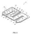
- FIG. 3 is a front perspective view of the heat exchanger of Figure 2.
- Figure 4 is a plan view of the heat exchanger of Figure 2.
- FIG. 5 is a front elevation view of the heat exchanger of Figure 4.
- Figure 6 is a cross-sectional view of Figure 4 as seen along viewing line VI-VI.
- Figure 7 is an enlarged view of a portion of the cross-section of Figure 7 as illustrated in detail C thereof.
- Figure 8 is an enlarged view of the cross-section of Figure 6 as seen in detail A thereof.
- Figure 9 is a cross-sectional view of Figure 4 as seen along viewing line IX-IX.
- Figure 10 is a cross-sectional view of Figure 4 as seen along viewing line X-X.
- Figure 11 is an enlarged view of the cross-section of Figure 6 as shown in detail B thereof.
- Figure 12 is a top perspective view of another embodiment of a compact clam shell heat exchanger in accordance with the present invention.
- Figure 13 is a front perspective view of the heat exchanger of Figure 12.
- FIG. 1 a compact hot air furnace 10 which includes heat exchangers in accordance with the present invention as described herein.
- the furnace 10 has a sheet metal outer covering 28 which encases a series of five heat exchangers 20, blower 14, burners 18, one for each heat exchanger 20, and gas and pressure regulator 16.
- Burners 18 are arranged so that they receive fuel gas from the pressure regulator 16, This gas is injected by burner 18 into the open end of a heat exchanger 20. As a part of the injection process, air is drawn into the heat exchanger so that the gas and the air may be combusted within the heat exchanger 20.
- a header 22 is connected to the exhaust portion of each of the heat exchangers and is also connected to an induction draft unit 24 which creates a suction pressure through the heat exchangers 20 to exhaust the discharged gases resulting from combustion through opening 26 to the discharge flue.
- Blower 14 receives cold room air from the area which is to be heated, forces that air over the heat exchanger surfaces in the direction indicated by arrow 12. The heated air is then collected and returned to the rooms to be heated.
- burners 18 are conventionally known burners, it should be appreciated that other suitable burners may be used in conjunction with the heat exchangers in a hot air furnace. For example, a one-piece burner for multiple-sectioned heat exchangers, as more fully described in commonly-owned. copending patent application U.S. Serial No, 10/299.479. entitled “One Shot Heat Exchanger Burner", may be used in place of burners 18, the disclosure of which is incorporated herein by reference for all purposes.
- Heat exchanger 20 as shown defines a serpentine configuration, including an inlet port 30, an exit port 32, and a four-pass serpentine passageway 34 communicating and interconnecting ports 30 and 32.
- Serpentine passageway 34 comprises four passageways, namely, inlet passageway 36, two intermediate passageways 38 and 40 and exhaust passageway 42.
- Inlet passageway 36 communicates with inlet port 30 and is connected to intermediate passageway 38 by a bend channel 44, Intermediate passageway 38 is interconnected with intermediate passageway 40 by a connecting channel 46.
- Intermediate passageway 40 is interconnected with exhaust passageway 42 by a connecting channel 48.
- Exhaust passageway 42 directly communicates with exhaust port 32.
- each one of the heat exchangers 20 includes a first lower plate member 20a and an upper plate member 20b secured together in face-to-face relation.
- the plate members 20a and 20b have surfaces stamped or otherwise formed into substantial mirror images of each other.
- the upper and lower plates 20a and 20b are folded and sealably crimped as shown at 20c in Figure 8 around the entire periphery of the heat exchanger 20, except at the inlet port 30 and exhaust port 32
- the upper and lower plates 20a and 20b are formed in accordance with the particular embodiment being described herein to provide an air space 50 between inlet passageway 36 and intermediate passageway 38, as well as an air space 52 between intermediate passageway 38 and intermediate passageway 40, as will be described.
- the lower plate 20a and the upper plate 20b of the heat exchanger 20 may be comprised of corrosion-resistant metallic materials, such as aluminized steel, 409 stainless steel, or a coated metal material. In the preferred embodiment, aluminized steel is used.
- heat exchanger 20 is provided with a longitudinally extending rib 58 and a plurality of inwardly projecting dimples 60, the details of which are illustrated in Figure 9.
- Longitudinally extending rib 58 extends substantially along the length of intermediate passageway 40, substantially centrally therewithin, effectively dividing passageway 40 into two smaller rectangular passageways 40a and 40b.
- the flow of the combustion products through passageway 40 is disrupted by the rib 58 causing the flow to be turbulent rather than laminar and effectively causing the hot central core of the combustion gases to flow outwardly toward the edges of the passageway 40, thereby increasing the uniformity of the heat distribution throughout passageway 40.
- Dimples 60 extending into passageway 40 further compound the turbulence caused by rib 58. As such, the dimples 60 create further obstacles within the gas flow stream resulting in additional mixing which increases the velocity of the combustion products through passageway 40. Additional dimples 60 are provided in connecting channel 48 as well as in exhaust passageway 42 to stimulate turbulent gas flow therewithin.
- Inlet passageway 36 has a generally elliptical cross-sectional area.
- Intermediate passageways 38 and 40 both have cross-sectional areas that are substantially identical, but less than the cross-sectional area of inlet passageway 36.
- Exhaust passageway 42 has a generally rectangular flattened cross-sectional area, less than the cross-sectional areas of intermediate passageways 38 and 40. The changing cross-sectional areas from the inlet passageway 36 to the exhaust passageway 42 assist in increasing the efficiency of heat transfer from the combustion gases to the heat exchanger walls.
- the cross-sectional area of inlet passageway 36 is 5.1 in 2 .
- the cross-sectional areas of intermediate passageways 38 and 40 (without rib 58) are each 3.8 in 2 .
- the cross-sectional area of passageway 40 through rib 58 is slightly reduced to 3.6 in 2 .
- the cross-sectional area of exhaust passageway 32 is 1.6 in 2 . It should be appreciated that these dimensions illustrate one particular arrangement and that the invention is not limited thereto.
- inlet passageway 36 With the serpentine heat exchanger inlet port 30 connected to the furnace burner, combustion typically occurs in the inlet passageway 36.
- inlet passageway into which the burner fires is the hottest and each subsequent passageway operates at a sequentially lower temperature as cooling air passing over the outer surfaces of the heat exchanger 20 removes the heat from the products of combustion.
- inlet passageway 36 is separated from intermediate passageway 38 by an air space 50 while the two intermediate passageways 38 and 40 are separated by air space 52. Air spaces 50 and 52 provide an additional degree of freedom for the thermal expansion and thereby act to minimize the mechanical stress due to temperature differentials in the heat exchanger.
- heat exchanger 20 comprises a drain shunt 62, defined by a generally tubular channel communicating with intermediate passageway 40 and exhaust passageway 42.
- Drain shunt 62 allows condensate (water vapor that may condense to liquid form on the internal surfaces of the heat exchanger 20) to drain from the heat exchanger in any orientation from vertical (inlet port 30 and exit port 32 being parallel to the acting force of gravity) to within a few degrees of horizontal (inlet port 30 and exhaust port 32 being perpendicular to the acting force of gravity), thereby improving resistance to corrosion and subsequently extending the life expectancy of the heat exchanger.
- Condensate may accumulate in heat exchangers 20 when the temperature of an internal wall drops below the dew point temperature of the air adjacent to the wall surface.
- the features of the heat exchanger described herein enhance desired heat exchanger performance in a hot-air furnace.
- the unique pattern of dimples 60 and rib 58 are used as internal flow obstructions to promote turbulence in localized high velocity swirl to force reformation of combustion gas boundary layers in the gas flow.
- the clinch hole fasteners 56 in the divider section 54 between intermediate passageway 40 and exhaust passageway 42 increase the rigidity of the divider section 54 and minimize leakage of combustion gases between the passageways 40 and 42.
- the walls of the clinch hole fasteners in the divider section 54 assist in creating further regions of flow disturbance that result in enhanced turbulence in passageways 40 and 42.
- heat exchanger 64 comprises a four-pass serpentine passageway 34' similar to heat exchanger 20.
- Heat exchanger 64 is constructed similar to the construction of heat exchanger 20 in that it includes an upper plate member and a lower plate member formed into substantially mirror images of each other, which are secured together in face-to-face relation. Unlike the heat exchanger 20, heat exchanger 64 does not have spaces, such as air gaps 50 and 52, between inlet passageway 36' and intermediate passageway 38' or between the two intermediate passageways 38' and 40'.
- Heat exchanger 64 comprises a single contiguous piece of sheet metal defining a lower plate member 64a and a single contiguous piece of sheet metal defining upper plate member 64b that are suitably mechanically crimped around the peripheral edges (except for the inlet port 30' and exhaust port 32') to form a gastight seal therearound.
- Flattened divider sections 66, 68 and 70 are respectively formed between inlet passageway 36' and intermediate passageway 38', between intermediate passageways 38' and 40', and between intermediate passageway 40' and exhaust passageway 42'.
- each of the divider sections 66, 68 and 70 in heat exchanger 64 are mechanically joined by a series of clinch hole fasteners 56' along each of the divider sections 66, 68 and 70.
- heat exchanger 64 also includes for enhanced turbulence and heat transfer efficiency, a plurality of dimples 60' extending within passageways 40' and 42', as well as a longitudinally extending centrally located rib 58' projecting within passageway 40'.
- a longitudinally extending rib 72 is formed to project internally of intermediate passageway 38', rib 72 extending longitudinally along a portion of the length of passageway 38'. Similar to rib 58', rib 72 serves as a gas flow splitter diverting the flow of gases outwardly toward the peripheral edges of the passageway 38' to thereby more uniformly distribute the heat and increase heat transfer efficiency.
- inlet passageway 36' is of generally elliptical configuration while the internal configurations of passageways 38', 40' and 42' are generally rectangular.
- the cross-sectional area of inlet passageway 36' is the largest of the passageways, while the cross-sectional area of the exhaust passageway 42' is the smallest.
- the cross-sectional areas of intermediate passageways 38' and 40' are substantially identical, each being smaller than the cross-sectional area of inlet passageway 36' but larger than the cross-sectional area of exhaust passageway 42'.
- inlet passageway 36' has a cross-sectional area of 3.0 in 2 and intermediate passageways 38' and 40' each have a cross-sectional area of 1.8 in 2 (without the respective ribs 72 and 58') and a cross-sectional area of 1.5 in (through respective ribs 72 and 58').
- Exhaust passageway 42' has a cross-sectional area of 0.7 in 2 .
- a drain shunt 52' is also provided between passageways 40' and 42' to allow any condensate to drain from the heat exchanger 64 as described hereinabove with respect to heat exchanger 20.
Landscapes
- Engineering & Computer Science (AREA)
- Physics & Mathematics (AREA)
- Thermal Sciences (AREA)
- Mechanical Engineering (AREA)
- General Engineering & Computer Science (AREA)
- Chemical & Material Sciences (AREA)
- Combustion & Propulsion (AREA)
- Heat-Exchange Devices With Radiators And Conduit Assemblies (AREA)
- Separation By Low-Temperature Treatments (AREA)
Applications Claiming Priority (2)
| Application Number | Priority Date | Filing Date | Title |
|---|---|---|---|
| US33657001P | 2001-12-05 | 2001-12-05 | |
| US336570P | 2001-12-05 |
Publications (3)
| Publication Number | Publication Date |
|---|---|
| EP1318362A2 true EP1318362A2 (de) | 2003-06-11 |
| EP1318362A3 EP1318362A3 (de) | 2004-04-21 |
| EP1318362B1 EP1318362B1 (de) | 2010-06-16 |
Family
ID=23316686
Family Applications (1)
| Application Number | Title | Priority Date | Filing Date |
|---|---|---|---|
| EP02080175A Expired - Lifetime EP1318362B1 (de) | 2001-12-05 | 2002-12-05 | Kompakter Plattenwärmetauscher mit hohem Wirkungsgrad |
Country Status (5)
| Country | Link |
|---|---|
| US (1) | US6938688B2 (de) |
| EP (1) | EP1318362B1 (de) |
| AT (1) | ATE471491T1 (de) |
| CA (1) | CA2413441A1 (de) |
| DE (1) | DE60236717D1 (de) |
Cited By (4)
| Publication number | Priority date | Publication date | Assignee | Title |
|---|---|---|---|---|
| EP1962043A1 (de) | 2007-02-22 | 2008-08-27 | Thomas & Betts International, Inc. | Mehrkanaliger Wärmetauscher |
| BE1020068A5 (nl) * | 2011-07-11 | 2013-04-02 | Multicalor Ind Nv | Warmtewisselaar voor een hoog rendement hete lucht verwarmingstoestel en verwarmingstoestel daarmee uitgerust. |
| US8646442B2 (en) | 2010-01-15 | 2014-02-11 | Lennox Industries Inc. | Clamshell heat exchanger |
| US20170125863A1 (en) * | 2015-11-04 | 2017-05-04 | Ford Global Technologies, Llc | Heat exchanger plate for electrified vehicle battery packs |
Families Citing this family (26)
| Publication number | Priority date | Publication date | Assignee | Title |
|---|---|---|---|---|
| JP5050241B2 (ja) * | 2007-01-29 | 2012-10-17 | 株式会社Kelk | 流体温調装置 |
| US7769467B1 (en) | 2007-01-31 | 2010-08-03 | Advanced Bionics, Llc | Level-dependent stimulation methods and systems |
| DE102007048046A1 (de) * | 2007-10-05 | 2009-04-09 | Nordson Corp., Westlake | Vorrichtung und Verfahren zur Abgabe eines Fluids, insbesondere Heißschmelzklebstoff |
| CN102227257A (zh) * | 2008-11-30 | 2011-10-26 | 康宁股份有限公司 | 具有高高宽比通道的蜂窝反应器 |
| US8122946B2 (en) * | 2009-06-16 | 2012-02-28 | Uop Llc | Heat exchanger with multiple channels and insulating channels |
| US9033030B2 (en) * | 2009-08-26 | 2015-05-19 | Munters Corporation | Apparatus and method for equalizing hot fluid exit plane plate temperatures in heat exchangers |
| US8875694B2 (en) * | 2010-01-15 | 2014-11-04 | Lennox Industries, Inc. | Converging-diverging combustion zones for furnace heat exchanges |
| US9770792B2 (en) | 2010-01-15 | 2017-09-26 | Lennox Industries Inc. | Heat exchanger having an interference rib |
| US8826901B2 (en) * | 2010-01-20 | 2014-09-09 | Carrier Corporation | Primary heat exchanger design for condensing gas furnace |
| US20120125311A1 (en) * | 2010-11-18 | 2012-05-24 | Thomas & Betts International, Inc. | Premix air heater |
| CN103649664B (zh) * | 2011-02-14 | 2017-08-15 | 马西米亚诺·比松 | 用于工厂等的辐射管状元件 |
| US9605871B2 (en) | 2012-02-17 | 2017-03-28 | Honeywell International Inc. | Furnace burner radiation shield |
| US8919337B2 (en) | 2012-02-17 | 2014-12-30 | Honeywell International Inc. | Furnace premix burner |
| DK2908786T3 (da) * | 2012-10-22 | 2020-03-09 | Univ Texas | Kompakt væskevarmer |
| US10126017B2 (en) | 2012-12-14 | 2018-11-13 | Lennox Industries Inc. | Strain reduction clamshell heat exchanger design |
| US10415903B2 (en) * | 2014-10-15 | 2019-09-17 | Hamilton Sundstrand Corporation | Prevention of cooling flow blockage |
| CA2911025C (en) | 2015-01-23 | 2020-03-10 | Heatco, Inc | Four pass high efficiency furnace and heat exchanger |
| US10544961B2 (en) * | 2016-02-18 | 2020-01-28 | Lennox Industries Inc. | Premix burner internal flue shield |
| US10697668B2 (en) | 2016-02-18 | 2020-06-30 | Lennox Industries Inc. | Flue baffle |
| US20180023895A1 (en) * | 2016-07-22 | 2018-01-25 | Trane International Inc. | Enhanced Tubular Heat Exchanger |
| US20180106500A1 (en) * | 2016-10-18 | 2018-04-19 | Trane International Inc. | Enhanced Tubular Heat Exchanger |
| US20180356106A1 (en) * | 2017-06-09 | 2018-12-13 | Trane International Inc. | Heat Exchanger Elevated Temperature Protection Sleeve |
| US20180372413A1 (en) * | 2017-06-22 | 2018-12-27 | Rheem Manufacturing Company | Heat Exchanger Tubes And Tube Assembly Configurations |
| KR102546993B1 (ko) * | 2018-07-26 | 2023-06-22 | 엘지전자 주식회사 | 가스 난방기 |
| FR3114873B1 (fr) * | 2020-10-07 | 2022-11-18 | Valeo Systemes Thermiques | Dispositif de régulation thermique, notamment de refroidissement pour véhicule automobile |
| US20220290896A1 (en) * | 2021-03-10 | 2022-09-15 | Lennox Industries Inc. | Clamshell Heat Exchangers |
Citations (3)
| Publication number | Priority date | Publication date | Assignee | Title |
|---|---|---|---|---|
| US4467780A (en) | 1977-08-29 | 1984-08-28 | Carrier Corporation | High efficiency clamshell heat exchanger |
| US4982785A (en) | 1990-03-06 | 1991-01-08 | Inter-City Products Corporation (Usa) | Serpentine heat exchanger |
| US5359989A (en) | 1993-03-04 | 1994-11-01 | Evcon Industries, Inc. | Furnace with heat exchanger |
Family Cites Families (33)
| Publication number | Priority date | Publication date | Assignee | Title |
|---|---|---|---|---|
| US3399661A (en) * | 1967-06-19 | 1968-09-03 | Kreis Philipp | Gas or liquid fuel fired space heater |
| US4006728A (en) * | 1971-02-13 | 1977-02-08 | Mitsubishi Denki Kabushiki Kaisha | Room heating apparatus using combustion |
| US4730600A (en) * | 1981-12-16 | 1988-03-15 | The Coleman Company, Inc. | Condensing furnace |
| US4478206A (en) * | 1984-01-05 | 1984-10-23 | Intertherm Inc. | Furnace having water vapor-condensing secondary heat exchanger |
| US4947548A (en) * | 1985-09-20 | 1990-08-14 | Carrier Corporation | Method of making a heat exchanger for condensing furnace |
| US4738307A (en) * | 1985-09-20 | 1988-04-19 | Carrier Corporation | Heat exchanger for condensing furnace |
| GB8811813D0 (en) * | 1988-05-19 | 1988-06-22 | York Int Ltd | Heat exchanger |
| US5010643A (en) * | 1988-09-15 | 1991-04-30 | Carrier Corporation | High performance heat transfer tube for heat exchanger |
| US5113844A (en) * | 1988-12-12 | 1992-05-19 | Vulcan Australia Limited | Heat exchanger |
| US4974579A (en) * | 1989-09-28 | 1990-12-04 | Rheem Manufacturing Company | Induced draft, fuel-fired furnace apparatus having an improved, high efficiency heat exchanger |
| USD335337S (en) * | 1990-05-18 | 1993-05-04 | Rheem Manufacturing Company | Heat exchanger for fuel fired furnaces |
| US5060722A (en) * | 1990-11-06 | 1991-10-29 | American Standard, Inc. | Furnace heat exchanger |
| US5074280A (en) * | 1991-03-13 | 1991-12-24 | Lennox Industries Inc. | Sectional high efficiency heat exchanger |
| US5271376A (en) * | 1991-08-12 | 1993-12-21 | Rheem Manufacturing Company | Serpentined tubular heat exchanger apparatus for a fuel-fired forced air heating furnace |
| US5203404A (en) * | 1992-03-02 | 1993-04-20 | Carrier Corporation | Heat exchanger tube |
| US5333598A (en) * | 1992-05-19 | 1994-08-02 | Modine Manufacturing Co. | Unit heater and heat exchanger therefor |
| US5301654A (en) * | 1992-07-29 | 1994-04-12 | Consolidated Industries Corp. | Heat-exchanger especially for forced air furnaces |
| US5267610A (en) * | 1992-11-09 | 1993-12-07 | Carrier Corporation | Heat exchanger and manufacturing method |
| US5332034A (en) * | 1992-12-16 | 1994-07-26 | Carrier Corporation | Heat exchanger tube |
| US5346001A (en) * | 1993-07-07 | 1994-09-13 | Carrier Corporation | Primary heat exchanger having improved heat transfer and condensate drainage |
| US5448986A (en) * | 1993-07-21 | 1995-09-12 | Lennox Industries Inc. | Heat exchanger |
| US5437263A (en) * | 1993-08-27 | 1995-08-01 | Goodman Manufacturing Company | High efficiency furnace method and apparatus |
| US5333682A (en) * | 1993-09-13 | 1994-08-02 | Carrier Corporation | Heat exchanger tube |
| USD360258S (en) * | 1993-12-10 | 1995-07-11 | Rheem Manufacturing Company | Heat exchanger for fuel fired furnaces |
| US5671808A (en) * | 1995-07-26 | 1997-09-30 | Kleyn; Hendrik | Polymeric radiators |
| US5623988A (en) * | 1995-09-25 | 1997-04-29 | Gas Research Institute | Polymeric heat exchanger with ceramic material insert |
| DE29713418U1 (de) | 1996-07-27 | 1998-03-05 | Fröling GmbH & Co., 51491 Overath | Heizkessel |
| US6109254A (en) * | 1997-10-07 | 2000-08-29 | Modine Manufacturing Company | Clamshell heat exchanger for a furnace or unit heater |
| US6006741A (en) * | 1998-08-31 | 1999-12-28 | Carrier Corporation | Secondary heat exchanger for condensing furnace |
| AU5167000A (en) | 1999-05-27 | 2000-12-18 | Thomas & Betts International, Inc. | Compact high-efficient air heater |
| US6422306B1 (en) * | 2000-09-29 | 2002-07-23 | International Comfort Products Corporation | Heat exchanger with enhancements |
| US6484798B1 (en) * | 2000-10-23 | 2002-11-26 | Carrier Corporation | Furnace heat exchanger |
| US6851469B2 (en) * | 2002-01-07 | 2005-02-08 | Carrier Corporation | Air baffle attachment to a heat exchanger |
-
2002
- 2002-11-19 US US10/299,314 patent/US6938688B2/en not_active Expired - Lifetime
- 2002-12-03 CA CA002413441A patent/CA2413441A1/en not_active Abandoned
- 2002-12-05 AT AT02080175T patent/ATE471491T1/de not_active IP Right Cessation
- 2002-12-05 DE DE60236717T patent/DE60236717D1/de not_active Expired - Lifetime
- 2002-12-05 EP EP02080175A patent/EP1318362B1/de not_active Expired - Lifetime
Patent Citations (3)
| Publication number | Priority date | Publication date | Assignee | Title |
|---|---|---|---|---|
| US4467780A (en) | 1977-08-29 | 1984-08-28 | Carrier Corporation | High efficiency clamshell heat exchanger |
| US4982785A (en) | 1990-03-06 | 1991-01-08 | Inter-City Products Corporation (Usa) | Serpentine heat exchanger |
| US5359989A (en) | 1993-03-04 | 1994-11-01 | Evcon Industries, Inc. | Furnace with heat exchanger |
Cited By (5)
| Publication number | Priority date | Publication date | Assignee | Title |
|---|---|---|---|---|
| EP1962043A1 (de) | 2007-02-22 | 2008-08-27 | Thomas & Betts International, Inc. | Mehrkanaliger Wärmetauscher |
| US8646442B2 (en) | 2010-01-15 | 2014-02-11 | Lennox Industries Inc. | Clamshell heat exchanger |
| BE1020068A5 (nl) * | 2011-07-11 | 2013-04-02 | Multicalor Ind Nv | Warmtewisselaar voor een hoog rendement hete lucht verwarmingstoestel en verwarmingstoestel daarmee uitgerust. |
| US20170125863A1 (en) * | 2015-11-04 | 2017-05-04 | Ford Global Technologies, Llc | Heat exchanger plate for electrified vehicle battery packs |
| US10727552B2 (en) * | 2015-11-04 | 2020-07-28 | Ford Global Technologies, Llc | Heat exchanger plate for electrified vehicle battery packs |
Also Published As
| Publication number | Publication date |
|---|---|
| DE60236717D1 (de) | 2010-07-29 |
| CA2413441A1 (en) | 2003-06-05 |
| EP1318362B1 (de) | 2010-06-16 |
| US20030102115A1 (en) | 2003-06-05 |
| ATE471491T1 (de) | 2010-07-15 |
| EP1318362A3 (de) | 2004-04-21 |
| US6938688B2 (en) | 2005-09-06 |
Similar Documents
| Publication | Publication Date | Title |
|---|---|---|
| US6938688B2 (en) | Compact high efficiency clam shell heat exchanger | |
| US6422306B1 (en) | Heat exchanger with enhancements | |
| CA2096372C (en) | Furnace with heat exchanger | |
| US4982785A (en) | Serpentine heat exchanger | |
| US5271376A (en) | Serpentined tubular heat exchanger apparatus for a fuel-fired forced air heating furnace | |
| US7240723B2 (en) | Tube bundle heat exchanger comprising tubes with expanded sections | |
| US6026804A (en) | Heater for fluids | |
| CA2358247C (en) | Furnace heat exchanger | |
| KR102702412B1 (ko) | 열교환기 유닛 | |
| CA2617763C (en) | Multi-channel heat exchanger | |
| US6564795B1 (en) | Air baffle attachment to a heat exchanger | |
| US6851469B2 (en) | Air baffle attachment to a heat exchanger | |
| CN111829363B (zh) | 换热器 | |
| US20230111255A1 (en) | Heat exchanger | |
| CN113028646A (zh) | 热交换器以及温水装置 | |
| EP3795922A1 (de) | Verteiler und brennkammer und warmwassererhitzer damit | |
| JPS5924140A (ja) | 熱交換器 | |
| KR102641390B1 (ko) | 열교환기 유닛 | |
| JP3038627B2 (ja) | 水管ボイラ | |
| JP3666777B2 (ja) | 燃焼ガス流に対し交差する熱吸収用フィンを設けたボイラ | |
| JPH1130401A (ja) | 燃焼ガス流に対し交差する熱吸収用フィンを設けたボイラ | |
| JP2515131B2 (ja) | 給湯装置 | |
| AU653692B2 (en) | Serpentined tubular heat exchanger apparatus for a fuel- fired forced air heating furnace | |
| JP3038626B2 (ja) | 水管ボイラの水管列 | |
| JPH0412324Y2 (de) |
Legal Events
| Date | Code | Title | Description |
|---|---|---|---|
| PUAI | Public reference made under article 153(3) epc to a published international application that has entered the european phase |
Free format text: ORIGINAL CODE: 0009012 |
|
| AK | Designated contracting states |
Designated state(s): AT BE BG CH CY CZ DE DK EE ES FI FR GB GR IE IT LI LU MC NL PT SE SI SK TR |
|
| AX | Request for extension of the european patent |
Extension state: AL LT LV MK RO |
|
| PUAL | Search report despatched |
Free format text: ORIGINAL CODE: 0009013 |
|
| AK | Designated contracting states |
Kind code of ref document: A3 Designated state(s): AT BE BG CH CY CZ DE DK EE ES FI FR GB GR IE IT LI LU MC NL PT SE SI SK TR |
|
| AX | Request for extension of the european patent |
Extension state: AL LT LV MK RO |
|
| 17P | Request for examination filed |
Effective date: 20040819 |
|
| AKX | Designation fees paid |
Designated state(s): AT BE BG CH CY CZ DE DK EE ES FI FR GB GR IE IT LI LU MC NL PT SE SI SK TR |
|
| 17Q | First examination report despatched |
Effective date: 20050324 |
|
| 17Q | First examination report despatched |
Effective date: 20050324 |
|
| GRAP | Despatch of communication of intention to grant a patent |
Free format text: ORIGINAL CODE: EPIDOSNIGR1 |
|
| GRAS | Grant fee paid |
Free format text: ORIGINAL CODE: EPIDOSNIGR3 |
|
| GRAA | (expected) grant |
Free format text: ORIGINAL CODE: 0009210 |
|
| AK | Designated contracting states |
Kind code of ref document: B1 Designated state(s): AT BE BG CH CY CZ DE DK EE ES FI FR GB GR IE IT LI LU MC NL PT SE SI SK TR |
|
| REG | Reference to a national code |
Ref country code: CH Ref legal event code: EP |
|
| REG | Reference to a national code |
Ref country code: IE Ref legal event code: FG4D |
|
| REF | Corresponds to: |
Ref document number: 60236717 Country of ref document: DE Date of ref document: 20100729 Kind code of ref document: P |
|
| REG | Reference to a national code |
Ref country code: NL Ref legal event code: VDEP Effective date: 20100616 |
|
| PG25 | Lapsed in a contracting state [announced via postgrant information from national office to epo] |
Ref country code: SE Free format text: LAPSE BECAUSE OF FAILURE TO SUBMIT A TRANSLATION OF THE DESCRIPTION OR TO PAY THE FEE WITHIN THE PRESCRIBED TIME-LIMIT Effective date: 20100616 |
|
| PG25 | Lapsed in a contracting state [announced via postgrant information from national office to epo] |
Ref country code: AT Free format text: LAPSE BECAUSE OF FAILURE TO SUBMIT A TRANSLATION OF THE DESCRIPTION OR TO PAY THE FEE WITHIN THE PRESCRIBED TIME-LIMIT Effective date: 20100616 Ref country code: SI Free format text: LAPSE BECAUSE OF FAILURE TO SUBMIT A TRANSLATION OF THE DESCRIPTION OR TO PAY THE FEE WITHIN THE PRESCRIBED TIME-LIMIT Effective date: 20100616 Ref country code: FI Free format text: LAPSE BECAUSE OF FAILURE TO SUBMIT A TRANSLATION OF THE DESCRIPTION OR TO PAY THE FEE WITHIN THE PRESCRIBED TIME-LIMIT Effective date: 20100616 |
|
| PG25 | Lapsed in a contracting state [announced via postgrant information from national office to epo] |
Ref country code: CY Free format text: LAPSE BECAUSE OF FAILURE TO SUBMIT A TRANSLATION OF THE DESCRIPTION OR TO PAY THE FEE WITHIN THE PRESCRIBED TIME-LIMIT Effective date: 20100616 Ref country code: GR Free format text: LAPSE BECAUSE OF FAILURE TO SUBMIT A TRANSLATION OF THE DESCRIPTION OR TO PAY THE FEE WITHIN THE PRESCRIBED TIME-LIMIT Effective date: 20100917 |
|
| PG25 | Lapsed in a contracting state [announced via postgrant information from national office to epo] |
Ref country code: NL Free format text: LAPSE BECAUSE OF FAILURE TO SUBMIT A TRANSLATION OF THE DESCRIPTION OR TO PAY THE FEE WITHIN THE PRESCRIBED TIME-LIMIT Effective date: 20100616 Ref country code: EE Free format text: LAPSE BECAUSE OF FAILURE TO SUBMIT A TRANSLATION OF THE DESCRIPTION OR TO PAY THE FEE WITHIN THE PRESCRIBED TIME-LIMIT Effective date: 20100616 |
|
| PG25 | Lapsed in a contracting state [announced via postgrant information from national office to epo] |
Ref country code: CZ Free format text: LAPSE BECAUSE OF FAILURE TO SUBMIT A TRANSLATION OF THE DESCRIPTION OR TO PAY THE FEE WITHIN THE PRESCRIBED TIME-LIMIT Effective date: 20100616 Ref country code: PT Free format text: LAPSE BECAUSE OF FAILURE TO SUBMIT A TRANSLATION OF THE DESCRIPTION OR TO PAY THE FEE WITHIN THE PRESCRIBED TIME-LIMIT Effective date: 20101018 Ref country code: SK Free format text: LAPSE BECAUSE OF FAILURE TO SUBMIT A TRANSLATION OF THE DESCRIPTION OR TO PAY THE FEE WITHIN THE PRESCRIBED TIME-LIMIT Effective date: 20100616 |
|
| PLBE | No opposition filed within time limit |
Free format text: ORIGINAL CODE: 0009261 |
|
| STAA | Information on the status of an ep patent application or granted ep patent |
Free format text: STATUS: NO OPPOSITION FILED WITHIN TIME LIMIT |
|
| PG25 | Lapsed in a contracting state [announced via postgrant information from national office to epo] |
Ref country code: DK Free format text: LAPSE BECAUSE OF FAILURE TO SUBMIT A TRANSLATION OF THE DESCRIPTION OR TO PAY THE FEE WITHIN THE PRESCRIBED TIME-LIMIT Effective date: 20100616 |
|
| 26N | No opposition filed |
Effective date: 20110317 |
|
| REG | Reference to a national code |
Ref country code: DE Ref legal event code: R097 Ref document number: 60236717 Country of ref document: DE Effective date: 20110316 |
|
| PG25 | Lapsed in a contracting state [announced via postgrant information from national office to epo] |
Ref country code: MC Free format text: LAPSE BECAUSE OF NON-PAYMENT OF DUE FEES Effective date: 20101231 |
|
| REG | Reference to a national code |
Ref country code: CH Ref legal event code: PL |
|
| PG25 | Lapsed in a contracting state [announced via postgrant information from national office to epo] |
Ref country code: CH Free format text: LAPSE BECAUSE OF NON-PAYMENT OF DUE FEES Effective date: 20101231 Ref country code: IE Free format text: LAPSE BECAUSE OF NON-PAYMENT OF DUE FEES Effective date: 20101205 Ref country code: LI Free format text: LAPSE BECAUSE OF NON-PAYMENT OF DUE FEES Effective date: 20101231 |
|
| REG | Reference to a national code |
Ref country code: DE Ref legal event code: R119 Ref document number: 60236717 Country of ref document: DE Effective date: 20110701 |
|
| PG25 | Lapsed in a contracting state [announced via postgrant information from national office to epo] |
Ref country code: DE Free format text: LAPSE BECAUSE OF NON-PAYMENT OF DUE FEES Effective date: 20110701 |
|
| PG25 | Lapsed in a contracting state [announced via postgrant information from national office to epo] |
Ref country code: BG Free format text: LAPSE BECAUSE OF FAILURE TO SUBMIT A TRANSLATION OF THE DESCRIPTION OR TO PAY THE FEE WITHIN THE PRESCRIBED TIME-LIMIT Effective date: 20100616 Ref country code: LU Free format text: LAPSE BECAUSE OF NON-PAYMENT OF DUE FEES Effective date: 20101205 |
|
| PG25 | Lapsed in a contracting state [announced via postgrant information from national office to epo] |
Ref country code: TR Free format text: LAPSE BECAUSE OF FAILURE TO SUBMIT A TRANSLATION OF THE DESCRIPTION OR TO PAY THE FEE WITHIN THE PRESCRIBED TIME-LIMIT Effective date: 20100616 |
|
| PG25 | Lapsed in a contracting state [announced via postgrant information from national office to epo] |
Ref country code: BG Free format text: LAPSE BECAUSE OF FAILURE TO SUBMIT A TRANSLATION OF THE DESCRIPTION OR TO PAY THE FEE WITHIN THE PRESCRIBED TIME-LIMIT Effective date: 20100916 |
|
| PG25 | Lapsed in a contracting state [announced via postgrant information from national office to epo] |
Ref country code: ES Free format text: LAPSE BECAUSE OF FAILURE TO SUBMIT A TRANSLATION OF THE DESCRIPTION OR TO PAY THE FEE WITHIN THE PRESCRIBED TIME-LIMIT Effective date: 20100927 |
|
| REG | Reference to a national code |
Ref country code: GB Ref legal event code: 732E Free format text: REGISTERED BETWEEN 20140410 AND 20140416 |
|
| REG | Reference to a national code |
Ref country code: FR Ref legal event code: CA Effective date: 20140610 Ref country code: FR Ref legal event code: TP Owner name: REZNOR MANUFACTURING COMPANY, LLC, US Effective date: 20140610 |
|
| REG | Reference to a national code |
Ref country code: FR Ref legal event code: PLFP Year of fee payment: 13 |
|
| REG | Reference to a national code |
Ref country code: FR Ref legal event code: PLFP Year of fee payment: 14 |
|
| REG | Reference to a national code |
Ref country code: FR Ref legal event code: PLFP Year of fee payment: 15 |
|
| PG25 | Lapsed in a contracting state [announced via postgrant information from national office to epo] |
Ref country code: IT Free format text: LAPSE BECAUSE OF NON-PAYMENT OF DUE FEES Effective date: 20151205 |
|
| PG25 | Lapsed in a contracting state [announced via postgrant information from national office to epo] |
Ref country code: IT Free format text: LAPSE BECAUSE OF NON-PAYMENT OF DUE FEES Effective date: 20151205 |
|
| PGRI | Patent reinstated in contracting state [announced from national office to epo] |
Ref country code: IT Effective date: 20170710 |
|
| REG | Reference to a national code |
Ref country code: FR Ref legal event code: PLFP Year of fee payment: 16 |
|
| PGFP | Annual fee paid to national office [announced via postgrant information from national office to epo] |
Ref country code: FR Payment date: 20171227 Year of fee payment: 16 |
|
| PGFP | Annual fee paid to national office [announced via postgrant information from national office to epo] |
Ref country code: GB Payment date: 20171227 Year of fee payment: 16 Ref country code: BE Payment date: 20171227 Year of fee payment: 16 |
|
| PGFP | Annual fee paid to national office [announced via postgrant information from national office to epo] |
Ref country code: IT Payment date: 20171221 Year of fee payment: 16 |
|
| GBPC | Gb: european patent ceased through non-payment of renewal fee |
Effective date: 20181205 |
|
| REG | Reference to a national code |
Ref country code: BE Ref legal event code: MM Effective date: 20181231 |
|
| PG25 | Lapsed in a contracting state [announced via postgrant information from national office to epo] |
Ref country code: IT Free format text: LAPSE BECAUSE OF NON-PAYMENT OF DUE FEES Effective date: 20181205 Ref country code: FR Free format text: LAPSE BECAUSE OF NON-PAYMENT OF DUE FEES Effective date: 20181231 |
|
| PG25 | Lapsed in a contracting state [announced via postgrant information from national office to epo] |
Ref country code: BE Free format text: LAPSE BECAUSE OF NON-PAYMENT OF DUE FEES Effective date: 20181231 |
|
| PG25 | Lapsed in a contracting state [announced via postgrant information from national office to epo] |
Ref country code: GB Free format text: LAPSE BECAUSE OF NON-PAYMENT OF DUE FEES Effective date: 20181205 |