EP1318367B1 - Verfahren und Vorrichtung zur kryogenischen Luftzerlegung - Google Patents
Verfahren und Vorrichtung zur kryogenischen Luftzerlegung Download PDFInfo
- Publication number
- EP1318367B1 EP1318367B1 EP01310153A EP01310153A EP1318367B1 EP 1318367 B1 EP1318367 B1 EP 1318367B1 EP 01310153 A EP01310153 A EP 01310153A EP 01310153 A EP01310153 A EP 01310153A EP 1318367 B1 EP1318367 B1 EP 1318367B1
- Authority
- EP
- European Patent Office
- Prior art keywords
- column
- auxiliary
- oxygen
- vapour
- nitrogen
- Prior art date
- Legal status (The legal status is an assumption and is not a legal conclusion. Google has not performed a legal analysis and makes no representation as to the accuracy of the status listed.)
- Expired - Lifetime
Links
Images


Classifications
-
- F—MECHANICAL ENGINEERING; LIGHTING; HEATING; WEAPONS; BLASTING
- F25—REFRIGERATION OR COOLING; COMBINED HEATING AND REFRIGERATION SYSTEMS; HEAT PUMP SYSTEMS; MANUFACTURE OR STORAGE OF ICE; LIQUEFACTION SOLIDIFICATION OF GASES
- F25J—LIQUEFACTION, SOLIDIFICATION OR SEPARATION OF GASES OR GASEOUS OR LIQUEFIED GASEOUS MIXTURES BY PRESSURE AND COLD TREATMENT OR BY BRINGING THEM INTO THE SUPERCRITICAL STATE
- F25J3/00—Processes or apparatus for separating the constituents of gaseous or liquefied gaseous mixtures involving the use of liquefaction or solidification
- F25J3/02—Processes or apparatus for separating the constituents of gaseous or liquefied gaseous mixtures involving the use of liquefaction or solidification by rectification, i.e. by continuous interchange of heat and material between a vapour stream and a liquid stream
- F25J3/04—Processes or apparatus for separating the constituents of gaseous or liquefied gaseous mixtures involving the use of liquefaction or solidification by rectification, i.e. by continuous interchange of heat and material between a vapour stream and a liquid stream for air
- F25J3/04406—Processes or apparatus for separating the constituents of gaseous or liquefied gaseous mixtures involving the use of liquefaction or solidification by rectification, i.e. by continuous interchange of heat and material between a vapour stream and a liquid stream for air using a dual pressure main column system
- F25J3/04412—Processes or apparatus for separating the constituents of gaseous or liquefied gaseous mixtures involving the use of liquefaction or solidification by rectification, i.e. by continuous interchange of heat and material between a vapour stream and a liquid stream for air using a dual pressure main column system in a classical double column flowsheet, i.e. with thermal coupling by a main reboiler-condenser in the bottom of low pressure respectively top of high pressure column
-
- F—MECHANICAL ENGINEERING; LIGHTING; HEATING; WEAPONS; BLASTING
- F25—REFRIGERATION OR COOLING; COMBINED HEATING AND REFRIGERATION SYSTEMS; HEAT PUMP SYSTEMS; MANUFACTURE OR STORAGE OF ICE; LIQUEFACTION SOLIDIFICATION OF GASES
- F25J—LIQUEFACTION, SOLIDIFICATION OR SEPARATION OF GASES OR GASEOUS OR LIQUEFIED GASEOUS MIXTURES BY PRESSURE AND COLD TREATMENT OR BY BRINGING THEM INTO THE SUPERCRITICAL STATE
- F25J3/00—Processes or apparatus for separating the constituents of gaseous or liquefied gaseous mixtures involving the use of liquefaction or solidification
- F25J3/02—Processes or apparatus for separating the constituents of gaseous or liquefied gaseous mixtures involving the use of liquefaction or solidification by rectification, i.e. by continuous interchange of heat and material between a vapour stream and a liquid stream
- F25J3/04—Processes or apparatus for separating the constituents of gaseous or liquefied gaseous mixtures involving the use of liquefaction or solidification by rectification, i.e. by continuous interchange of heat and material between a vapour stream and a liquid stream for air
- F25J3/04248—Generation of cold for compensating heat leaks or liquid production, e.g. by Joule-Thompson expansion
- F25J3/04284—Generation of cold for compensating heat leaks or liquid production, e.g. by Joule-Thompson expansion using internal refrigeration by open-loop gas work expansion, e.g. of intermediate or oxygen enriched (waste-)streams
- F25J3/0429—Generation of cold for compensating heat leaks or liquid production, e.g. by Joule-Thompson expansion using internal refrigeration by open-loop gas work expansion, e.g. of intermediate or oxygen enriched (waste-)streams of feed air, e.g. used as waste or product air or expanded into an auxiliary column
- F25J3/04303—Lachmann expansion, i.e. expanded into oxygen producing or low pressure column
-
- F—MECHANICAL ENGINEERING; LIGHTING; HEATING; WEAPONS; BLASTING
- F25—REFRIGERATION OR COOLING; COMBINED HEATING AND REFRIGERATION SYSTEMS; HEAT PUMP SYSTEMS; MANUFACTURE OR STORAGE OF ICE; LIQUEFACTION SOLIDIFICATION OF GASES
- F25J—LIQUEFACTION, SOLIDIFICATION OR SEPARATION OF GASES OR GASEOUS OR LIQUEFIED GASEOUS MIXTURES BY PRESSURE AND COLD TREATMENT OR BY BRINGING THEM INTO THE SUPERCRITICAL STATE
- F25J3/00—Processes or apparatus for separating the constituents of gaseous or liquefied gaseous mixtures involving the use of liquefaction or solidification
- F25J3/02—Processes or apparatus for separating the constituents of gaseous or liquefied gaseous mixtures involving the use of liquefaction or solidification by rectification, i.e. by continuous interchange of heat and material between a vapour stream and a liquid stream
- F25J3/04—Processes or apparatus for separating the constituents of gaseous or liquefied gaseous mixtures involving the use of liquefaction or solidification by rectification, i.e. by continuous interchange of heat and material between a vapour stream and a liquid stream for air
- F25J3/04436—Processes or apparatus for separating the constituents of gaseous or liquefied gaseous mixtures involving the use of liquefaction or solidification by rectification, i.e. by continuous interchange of heat and material between a vapour stream and a liquid stream for air using at least a triple pressure main column system
- F25J3/04448—Processes or apparatus for separating the constituents of gaseous or liquefied gaseous mixtures involving the use of liquefaction or solidification by rectification, i.e. by continuous interchange of heat and material between a vapour stream and a liquid stream for air using at least a triple pressure main column system in a double column flowsheet with an intermediate pressure column
-
- F—MECHANICAL ENGINEERING; LIGHTING; HEATING; WEAPONS; BLASTING
- F25—REFRIGERATION OR COOLING; COMBINED HEATING AND REFRIGERATION SYSTEMS; HEAT PUMP SYSTEMS; MANUFACTURE OR STORAGE OF ICE; LIQUEFACTION SOLIDIFICATION OF GASES
- F25J—LIQUEFACTION, SOLIDIFICATION OR SEPARATION OF GASES OR GASEOUS OR LIQUEFIED GASEOUS MIXTURES BY PRESSURE AND COLD TREATMENT OR BY BRINGING THEM INTO THE SUPERCRITICAL STATE
- F25J3/00—Processes or apparatus for separating the constituents of gaseous or liquefied gaseous mixtures involving the use of liquefaction or solidification
- F25J3/02—Processes or apparatus for separating the constituents of gaseous or liquefied gaseous mixtures involving the use of liquefaction or solidification by rectification, i.e. by continuous interchange of heat and material between a vapour stream and a liquid stream
- F25J3/04—Processes or apparatus for separating the constituents of gaseous or liquefied gaseous mixtures involving the use of liquefaction or solidification by rectification, i.e. by continuous interchange of heat and material between a vapour stream and a liquid stream for air
- F25J3/04436—Processes or apparatus for separating the constituents of gaseous or liquefied gaseous mixtures involving the use of liquefaction or solidification by rectification, i.e. by continuous interchange of heat and material between a vapour stream and a liquid stream for air using at least a triple pressure main column system
- F25J3/04454—Processes or apparatus for separating the constituents of gaseous or liquefied gaseous mixtures involving the use of liquefaction or solidification by rectification, i.e. by continuous interchange of heat and material between a vapour stream and a liquid stream for air using at least a triple pressure main column system a main column system not otherwise provided, e.g. serially coupling of columns or more than three pressure levels
-
- F—MECHANICAL ENGINEERING; LIGHTING; HEATING; WEAPONS; BLASTING
- F25—REFRIGERATION OR COOLING; COMBINED HEATING AND REFRIGERATION SYSTEMS; HEAT PUMP SYSTEMS; MANUFACTURE OR STORAGE OF ICE; LIQUEFACTION SOLIDIFICATION OF GASES
- F25J—LIQUEFACTION, SOLIDIFICATION OR SEPARATION OF GASES OR GASEOUS OR LIQUEFIED GASEOUS MIXTURES BY PRESSURE AND COLD TREATMENT OR BY BRINGING THEM INTO THE SUPERCRITICAL STATE
- F25J3/00—Processes or apparatus for separating the constituents of gaseous or liquefied gaseous mixtures involving the use of liquefaction or solidification
- F25J3/02—Processes or apparatus for separating the constituents of gaseous or liquefied gaseous mixtures involving the use of liquefaction or solidification by rectification, i.e. by continuous interchange of heat and material between a vapour stream and a liquid stream
- F25J3/04—Processes or apparatus for separating the constituents of gaseous or liquefied gaseous mixtures involving the use of liquefaction or solidification by rectification, i.e. by continuous interchange of heat and material between a vapour stream and a liquid stream for air
- F25J3/04763—Start-up or control of the process; Details of the apparatus used
- F25J3/04866—Construction and layout of air fractionation equipments, e.g. valves, machines
- F25J3/04872—Vertical layout of cold equipments within in the cold box, e.g. columns, heat exchangers etc.
-
- F—MECHANICAL ENGINEERING; LIGHTING; HEATING; WEAPONS; BLASTING
- F25—REFRIGERATION OR COOLING; COMBINED HEATING AND REFRIGERATION SYSTEMS; HEAT PUMP SYSTEMS; MANUFACTURE OR STORAGE OF ICE; LIQUEFACTION SOLIDIFICATION OF GASES
- F25J—LIQUEFACTION, SOLIDIFICATION OR SEPARATION OF GASES OR GASEOUS OR LIQUEFIED GASEOUS MIXTURES BY PRESSURE AND COLD TREATMENT OR BY BRINGING THEM INTO THE SUPERCRITICAL STATE
- F25J3/00—Processes or apparatus for separating the constituents of gaseous or liquefied gaseous mixtures involving the use of liquefaction or solidification
- F25J3/02—Processes or apparatus for separating the constituents of gaseous or liquefied gaseous mixtures involving the use of liquefaction or solidification by rectification, i.e. by continuous interchange of heat and material between a vapour stream and a liquid stream
- F25J3/04—Processes or apparatus for separating the constituents of gaseous or liquefied gaseous mixtures involving the use of liquefaction or solidification by rectification, i.e. by continuous interchange of heat and material between a vapour stream and a liquid stream for air
- F25J3/04763—Start-up or control of the process; Details of the apparatus used
- F25J3/04866—Construction and layout of air fractionation equipments, e.g. valves, machines
- F25J3/04896—Details of columns, e.g. internals, inlet/outlet devices
- F25J3/04933—Partitioning walls or sheets
- F25J3/04939—Vertical, e.g. dividing wall columns
-
- F—MECHANICAL ENGINEERING; LIGHTING; HEATING; WEAPONS; BLASTING
- F25—REFRIGERATION OR COOLING; COMBINED HEATING AND REFRIGERATION SYSTEMS; HEAT PUMP SYSTEMS; MANUFACTURE OR STORAGE OF ICE; LIQUEFACTION SOLIDIFICATION OF GASES
- F25J—LIQUEFACTION, SOLIDIFICATION OR SEPARATION OF GASES OR GASEOUS OR LIQUEFIED GASEOUS MIXTURES BY PRESSURE AND COLD TREATMENT OR BY BRINGING THEM INTO THE SUPERCRITICAL STATE
- F25J2200/00—Processes or apparatus using separation by rectification
- F25J2200/32—Processes or apparatus using separation by rectification using a side column fed by a stream from the high pressure column
-
- F—MECHANICAL ENGINEERING; LIGHTING; HEATING; WEAPONS; BLASTING
- F25—REFRIGERATION OR COOLING; COMBINED HEATING AND REFRIGERATION SYSTEMS; HEAT PUMP SYSTEMS; MANUFACTURE OR STORAGE OF ICE; LIQUEFACTION SOLIDIFICATION OF GASES
- F25J—LIQUEFACTION, SOLIDIFICATION OR SEPARATION OF GASES OR GASEOUS OR LIQUEFIED GASEOUS MIXTURES BY PRESSURE AND COLD TREATMENT OR BY BRINGING THEM INTO THE SUPERCRITICAL STATE
- F25J2200/00—Processes or apparatus using separation by rectification
- F25J2200/34—Processes or apparatus using separation by rectification using a side column fed by a stream from the low pressure column
-
- F—MECHANICAL ENGINEERING; LIGHTING; HEATING; WEAPONS; BLASTING
- F25—REFRIGERATION OR COOLING; COMBINED HEATING AND REFRIGERATION SYSTEMS; HEAT PUMP SYSTEMS; MANUFACTURE OR STORAGE OF ICE; LIQUEFACTION SOLIDIFICATION OF GASES
- F25J—LIQUEFACTION, SOLIDIFICATION OR SEPARATION OF GASES OR GASEOUS OR LIQUEFIED GASEOUS MIXTURES BY PRESSURE AND COLD TREATMENT OR BY BRINGING THEM INTO THE SUPERCRITICAL STATE
- F25J2200/00—Processes or apparatus using separation by rectification
- F25J2200/90—Details relating to column internals, e.g. structured packing, gas or liquid distribution
- F25J2200/96—Dividing wall column
-
- F—MECHANICAL ENGINEERING; LIGHTING; HEATING; WEAPONS; BLASTING
- F25—REFRIGERATION OR COOLING; COMBINED HEATING AND REFRIGERATION SYSTEMS; HEAT PUMP SYSTEMS; MANUFACTURE OR STORAGE OF ICE; LIQUEFACTION SOLIDIFICATION OF GASES
- F25J—LIQUEFACTION, SOLIDIFICATION OR SEPARATION OF GASES OR GASEOUS OR LIQUEFIED GASEOUS MIXTURES BY PRESSURE AND COLD TREATMENT OR BY BRINGING THEM INTO THE SUPERCRITICAL STATE
- F25J2205/00—Processes or apparatus using other separation and/or other processing means
- F25J2205/30—Processes or apparatus using other separation and/or other processing means using a washing, e.g. "scrubbing" or bubble column for purification purposes
-
- F—MECHANICAL ENGINEERING; LIGHTING; HEATING; WEAPONS; BLASTING
- F25—REFRIGERATION OR COOLING; COMBINED HEATING AND REFRIGERATION SYSTEMS; HEAT PUMP SYSTEMS; MANUFACTURE OR STORAGE OF ICE; LIQUEFACTION SOLIDIFICATION OF GASES
- F25J—LIQUEFACTION, SOLIDIFICATION OR SEPARATION OF GASES OR GASEOUS OR LIQUEFIED GASEOUS MIXTURES BY PRESSURE AND COLD TREATMENT OR BY BRINGING THEM INTO THE SUPERCRITICAL STATE
- F25J2245/00—Processes or apparatus involving steps for recycling of process streams
- F25J2245/40—Processes or apparatus involving steps for recycling of process streams the recycled stream being air
-
- F—MECHANICAL ENGINEERING; LIGHTING; HEATING; WEAPONS; BLASTING
- F25—REFRIGERATION OR COOLING; COMBINED HEATING AND REFRIGERATION SYSTEMS; HEAT PUMP SYSTEMS; MANUFACTURE OR STORAGE OF ICE; LIQUEFACTION SOLIDIFICATION OF GASES
- F25J—LIQUEFACTION, SOLIDIFICATION OR SEPARATION OF GASES OR GASEOUS OR LIQUEFIED GASEOUS MIXTURES BY PRESSURE AND COLD TREATMENT OR BY BRINGING THEM INTO THE SUPERCRITICAL STATE
- F25J2245/00—Processes or apparatus involving steps for recycling of process streams
- F25J2245/42—Processes or apparatus involving steps for recycling of process streams the recycled stream being nitrogen
-
- F—MECHANICAL ENGINEERING; LIGHTING; HEATING; WEAPONS; BLASTING
- F25—REFRIGERATION OR COOLING; COMBINED HEATING AND REFRIGERATION SYSTEMS; HEAT PUMP SYSTEMS; MANUFACTURE OR STORAGE OF ICE; LIQUEFACTION SOLIDIFICATION OF GASES
- F25J—LIQUEFACTION, SOLIDIFICATION OR SEPARATION OF GASES OR GASEOUS OR LIQUEFIED GASEOUS MIXTURES BY PRESSURE AND COLD TREATMENT OR BY BRINGING THEM INTO THE SUPERCRITICAL STATE
- F25J2290/00—Other details not covered by groups F25J2200/00 - F25J2280/00
- F25J2290/10—Mathematical formulae, modeling, plot or curves; Design methods
-
- Y—GENERAL TAGGING OF NEW TECHNOLOGICAL DEVELOPMENTS; GENERAL TAGGING OF CROSS-SECTIONAL TECHNOLOGIES SPANNING OVER SEVERAL SECTIONS OF THE IPC; TECHNICAL SUBJECTS COVERED BY FORMER USPC CROSS-REFERENCE ART COLLECTIONS [XRACs] AND DIGESTS
- Y10—TECHNICAL SUBJECTS COVERED BY FORMER USPC
- Y10S—TECHNICAL SUBJECTS COVERED BY FORMER USPC CROSS-REFERENCE ART COLLECTIONS [XRACs] AND DIGESTS
- Y10S62/00—Refrigeration
- Y10S62/90—Triple column
Definitions
- the present invention relates to the field of cryogenic air distillation using an air separation unit ("ASU") comprising more than one cryogenic distillation column.
- ASU air separation unit
- the present invention has particular application to an ASU having a thermally integrated double column distillation system comprising a higher pressure (“HP") column and a lower pressure (“LP”) column.
- HP higher pressure
- LP lower pressure
- the distillation columns of an ASU have a plurality of column sections.
- the hydraulic loading of the various column sections can vary significantly and it is common to use two or more different diameters for the column sections, especially when structured packing is used as the mass transfer elements in the columns.
- the upper sections of the LP column of a double column system usually determine the largest diameter used in the column system, as it is at this location that typically the column system has the largest volumetric flow of vapour. For a defined maximum column diameter in the double column system, the upper sections of the LP column are usually the bottleneck for the capacity rating of the column system.
- the HP column and lower sections of the LP column would allow a higher plant capacity if their diameters were increased towards the stated maximum diameter value. If the double column capacity could be increased without increasing the maximum double column section diameter then the footprint of the column system and associated piping would be largely unchanged.
- An advantage of reducing the flow bottleneck in the upper sections of the LP column would be that the capacity of the double column system could be increased (under the constraint of a particular defined maximum column diameter). In addition, the ability for very large columns to be shipped is often determined by the maximum column section diameter. If the above flow bottleneck could be reduced then the maximum capacity of a single train double column could be increased.
- US-A-5100448 (published on 31st March 1992) discloses a column system using structured packing, where a lower density (higher capacity) structured packing is used in column sections having a high hydraulic load and higher density (lower capacity) packing is used in sections having a low hydraulic load. While this could achieve the objective mentioned above, low density packing has substantially poorer mass transfer performance than higher density packing.
- US-A-6128921 (published on 10th October 2000) discloses an arrangement of multiple LP columns to increase the capacity of the plant, with each LP column providing part of the product. It does not address the problem that it is only the upper sections of the LP column that cause the initial capacity bottleneck for the double column system.
- EP-A-1271081 discloses a process for separating a multi-component fluid comprising oxygen and nitrogen to produce nitrogen.
- the process uses a multiple distillation column system comprising a higher pressure column operating at a first pressure, a lower pressure column operating at a second pressure lower than the first pressure and a supplemental column operating at a third pressure greater than or equal to the second pressure.
- a multiple distillation column system comprising a higher pressure column operating at a first pressure, a lower pressure column operating at a second pressure lower than the first pressure and a supplemental column operating at a third pressure greater than or equal to the second pressure.
- the inventor has found that this can be achieved by routing a small fraction of the vapour flow which would normally pass through the upper LP column sections through an auxiliary separation column which is refluxed by a liquid stream from or derived from the HP column.
- the vapour flow rate in the auxiliary column is less than about 25%, preferably less than about 20% and most preferably less than about 15%, of the vapour flow rate in the upper LP column sections. Bottoms liquid from the auxiliary column is returned to the LP column at an intermediate location above the bottom section.
- a process for the cryogenic separation of air using a multiple column distillation system comprising at least an HP column and an LP column, said LP column having a number of distillation sections, said process comprising:
- the vapour flow rate in the auxiliary column is less than about 25%, preferably less than about 20% and most preferably less than about 15%, of the vapour flow in the upper LP column sections.
- the oxygen-containing gas may comprise from about 50 to about 10 mol % oxygen.
- the oxygen-containing gas comprises gas removed from an intermediate location in the LP column.
- the gas is removed from a location below the upper sections of the LP column having the highest volumetric flow of vapour in the LP column.
- the oxygen-containing gas comprises flash vapour produced from reducing the pressure of at least a portion of the CLOX produced in the HP column.
- the quantity of CLOX flash vapour formed if the CLOX is not subcooled can be as high as 15 mol % of the CLOX flow.
- the flash vapour could be separated from any CLOX remaining after pressure reduction outside the column system before being fed to the auxiliary separation column. However, it is convenient to feed the CLOX stream to the auxiliary separation column, ideally to the bottom of the column, where it would be separated in the sump of the column.
- the oxygen-containing gas comprises a proportion of the feed air to the distillation system.
- the oxygen-containing gas preferably comprises at least a portion of a discharge stream from an air expansion turbine. Part of the turbine discharge stream may be fed to the LP column.
- Oxygen-containing gas from two or more of these sources may be fed to the auxiliary column at any one time.
- the auxiliary column may be fed with CLOX flash vapour supplemented by oxygen-containing gas removed from an intermediate location in the LP column and/or discharged from an air expansion turbine.
- the operating pressure of the auxiliary separation column is the same as the operating pressure of the LP column.
- GAN gaseous nitrogen
- auxiliary column nitrogen-rich overhead vapour removed from the auxiliary column, without pressure adjustment, to form a combined nitrogen product stream.
- the operating pressure of the auxiliary separation column may different from the operating pressure of the LP column. Pressure adjustment would, therefore, be required for any streams travelling between the LP column and the auxiliary pressure separation column.
- the process further comprises removing HP nitrogen-enriched overhead vapour from the top of the HP column, condensing at least a portion thereof in a reboiler/condenser located in the bottom of the LP column and feeding at least a portion of the condensed nitrogen as reflux to the HP column.
- the LP column and the auxiliary column may be refluxed with condensed nitrogen produced in the reboiler/condenser or with fluid removed from an intermediate location in the HP column.
- the source of the reflux for the LP column is not necessarily the same as that for the auxiliary column.
- the auxiliary column is usually refluxed with condensed nitrogen produced in the reboiler/condenser.
- liquid air may also be fed to the HP column for certain process cycles.
- a portion of the HP nitrogen-enriched overhead vapour may be removed as HPGAN product.
- a portion of the nitrogen condensed in the reboiler/condenser could be removed as a liquid nitrogen ("LIN") product.
- CLOX may be subjected to heat transfer or distillation before being fed to the LP column. Some processes may require a liquid air feed and/or an air expander exhaust feed to the LP column.
- Liquid feed streams to the columns may be subcooled.
- apparatus for the cryogenic separation of air by the process according to the first aspect comprising:
- the size of the auxiliary separation column is such that the auxiliary column can accommodate a vapour flow rate of less than about 25%, preferably less than about 20% and most preferably less than about 15%, of the vapour flow rate in the upper LP column sections.
- the apparatus further comprises conduit means for feeding oxygen-containing gas from an intermediate location in the LP column to the auxiliary separation column.
- the intermediate location should be below the upper sections of the LP column having the highest volumetric flow of vapour in the LP column.
- the apparatus further comprises pressure reduction means for producing flash vapour from CLOX removed from the HP column and conduit means for feeding said flash vapour to the auxiliary separation column.
- the apparatus further comprises conduit means for feeding to the auxiliary column a proportion of the feed air to the distillation system.
- the apparatus preferably further comprises an air expansion turbine and conduit means for feeding at least a portion of a discharge stream from said turbine to the auxiliary separation column.
- the apparatus may comprise any combination of the features of these preferred embodiments.
- the apparatus will further comprise:
- the auxiliary column may be located anywhere in space relative to the multiple column distillation system.
- the auxiliary column is preferably elevated such that oxygen-rich liquid in the bottom of the column can be fed to the LP column under gravity although it could be located alongside the LP column or even below the LP column and oxygen-rich bottoms liquid may be pumped to the LP column.
- the auxiliary column will be located directly above the LP column.
- the tophat section and the auxiliary column could be integrated to form a divided column.
- any geometry may be used to divide the cross-section or the two columns, for example, in embodiments where the auxiliary column is located alongside the tophat section, the auxiliary column could surround the tophat section or vice versa in an annular configuration.
- the columns may be sectors or segments of a common outer circular shell or even a square column inside a column. Any suitable configuration of divided column may be used.
- the auxiliary column vapour flow rate is usually less than 25% of the vapour flow rate in the upper sections of the LP column.
- the addition of the auxiliary column specifically addresses the situation that it is only the upper sections of the LP column that determine the maximum double column section diameter. By use of the invention, either the maximum column diameter may be reduced or the double column system capacity increased.
- standard higher density packing having excellent mass transfer characteristics can be used in all sections of the columns (in contrast to the teaching of US-A-5100448).
- the auxiliary column is relatively inexpensive as it has a diameter that is usually less than that for the LP column and does not require many theoretical stages for mass transfer. In addition, it does not require any additional reboilers or condensers if prior art cycles are to be adapted by way of the invention.
- the capacity of a typical double column distillation system can be significantly increased by the addition of an auxiliary column having a vapour flow rate of usually less than 25% of that in the upper sections of the LP column.
- the auxiliary column typically has less than fifteen and preferably about ten theoretical stages of separation which allows it to be located such that the capacity increase of the multiple column is achieved while having minimal impact on the size of the cold enclosure.
- cooled compressed air 100 is fed to the HP column 10.
- a liquid air stream 102 may also be fed to the HP column 10 for some process cycles.
- separation is effected to give an overhead nitrogen-enriched stream, part of which could optionally be withdrawn as product HPGAN and the balance condensed in reboiler 20.
- Part of the condensed nitrogen is returned to the HP column 10 as reflux and the balance is withdrawn as stream 110 to provide reflux for the LP column 30 (and, optionally, a LIN product).
- a CLOX stream 120 is withdrawn from the HP column 10 and passed to an intermediate point of the LP column 30 (optionally after being subjected to heat transfer or distillation in unshown columns or exchangers).
- the LP column 30 may also have a liquid air feed stream 104 and/or an expander discharge/exhaust feed stream 106.
- the liquid streams feeding the columns may be subcooled but such subcooling is not shown in the figures.
- the LP column 30 separation is effected to give an overhead waste nitrogen stream 130 and a bottoms oxygen product stream 140.
- the LP column is shown as having three sections I, II, III although there would be a further section in the system of Figure 1 if the expander stream 106 entered the column at a different point than the CLOX stream 120. Also there could be additional sections in the lower zone of the LP column if the process cycle included additional columns or exchangers, which were used to pretreat the CLOX feed and/or produce argon.
- a vapour stream 150 having an oxygen concentration of less than about 50 mol % O 2 but more than about 10 mol % O 2 is withdrawn from the LP column 30 from below the most highly loaded sections II, III and routed to the bottom of auxiliary separation column 40 where it is separated into oxygen-rich liquid and auxiliary column nitrogen-rich overhead vapour.
- the flowrate of stream 150 is typically determined such that the upper sections II, III of the LP column 30 no longer have to have a diameter larger than any other double column section diameter.
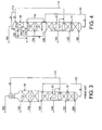
- the auxiliary column 40 is provided with at least a reflux stream 112 originating from the HP column 10. Oxygen-rich liquid from the auxiliary column 40 is passed as stream 154 back to an intermediate point in the LP column 30. The overhead vapour stream 152 from the auxiliary column 40 is combined with the waste nitrogen gas stream 130 from the LP column 30.
- the auxiliary column 40 is shown located above the LP column, but the auxiliary column 40 could be located elsewhere.
- the auxiliary column 40 is elevated such that the oxygen-rich liquid can pass to the LP column 40 under gravity.
- Figure 3 depicts a double column system of the prior art.
- the system of this figure is different from that of Figure 1 in that there is an additional "tophat" section IV in the LP column 30 for the production of LPGAN product which is removed as stream 160.
- the tophat section IV of the LP column 30 is typical in that it has a smaller diameter than section III because part of the overhead vapour from section III is withdrawn as waste nitrogen in stream 130.
- LP column upper sections II, III are the most highly loaded sections and, thus, are typical in that they have larger diameters than the rest of the double column sections.
- Figure 4 depicts one possible arrangement in which the system depicted in Figure 3 has been adapted to include the auxiliary column 40.
- the auxiliary column 40 processes a fraction of the vapour rising inside the LP column 30 to unload sections II, III.
- the auxiliary column 40 is shown alongside the LP column tophat section IV as divided columns but it is to be understood that the auxiliary column 40 could surround the tophat section IV or vice versa in an annular configuration.
- the auxiliary column 40 could, instead, be located above or alongside the LP column 30.
- the vapour processed by the auxiliary column 40 originates from an intermediate location of the LP column 30.
- any source of low pressure vapour which would otherwise pass up through the LP column to the waste nitrogen take-off point can be used.
- the source of the low pressure vapour processed by the auxiliary column 40 is flash vapour formed when CLOX is reduced in pressure to form a stream 120 of CLOX comprising flash vapour.
- the quantity of CLOX flash vapour formed if the CLOX is not subcooled can be as high as 15 mol % of the CLOX flow.
- This flash vapour could be separated outside the auxiliary column 40 but it is convenient to route the unseparated CLOX stream 120 into the bottom of column 40 as shown in Figure 5 and use the sump as a separator.
- auxiliary column 40 could be operated at a different pressure to the LP column 30 and the stream 152 of nitrogen-rich overhead vapour could then be withdrawn as a separate product stream rather than being mixed with stream 130 as shown.
- auxiliary column 40 of the system in Figure 6 could be operated at a different pressure than the LP column 30 and stream 152 recovered as a separate product stream rather than being mixed with stream 130 as shown.
- the flashgas in CLOX stream 120 passes up through the auxiliary column.
- the flow of waste gas 152 leaving the auxiliary column 40 is about 10% of the total waste gas flow and, thus, section III of the LP column 30 only has to pass about 90% of the total waste gas flow.
- the purities of the waste gases leaving the auxiliary column 40 and the LP column 30 as streams 152 and 130 respectively are approximately the same.
- 10% of the total waste nitrogen gas is produced as stream 152 from the auxiliary column 40, slightly more than 10% (actually 10.6%) of the total reflux is routed to the auxiliary column 40, i.e. the auxiliary column typically runs with a liquid to vapour ratio slightly higher than in section III of the LP column.
- section I The cross-sectional area of section I is unchanged. However, for section III, the cross sectional area is about 10% lower than for the plant designed according to Figure 1, for the same approach to flood.
- the auxiliary column cross-sectional area is only about 11 % of that for section III and only requires about ten theoretical stages. Minimal energy consumption differences are found for the two designs as, in the Figure 5 design, power consumption is less than 0.1% greater than that encountered using the Figure 1 design.
Landscapes
- Engineering & Computer Science (AREA)
- Physics & Mathematics (AREA)
- Mechanical Engineering (AREA)
- Thermal Sciences (AREA)
- General Engineering & Computer Science (AREA)
- Separation By Low-Temperature Treatments (AREA)
Claims (27)
- Prozess für die Tieftemperaturzerlegung von Luft unter Verwendung eines Mehrsäulen-Destillationssystems, das wenigstens eine Säule (10) mit höherem Druck ("HP"-Säule) und eine Säule (30) mit niedrigerem Druck ("LP"-Säule) umfasst,
wobei die LP-Säule (30) zahlreiche Destillationssäulenabschnitte besitzt, wobei der Prozess umfasst:Zuführen (100) von gekühlter Zufuhrluft zu der HP-Säule (10) für eine Zerlegung in stickstoffangereicherten HP-Kopfdestillatdampf und unbehandelten flüssigen Sauerstoff ("CLOX");Zuführen (104, 106, 120) wenigstens eines LP-Säulen-Zufuhrstroms, der Stickstoff und Sauerstoff enthält, zu der LP-Säule (30), um ihn in stickstoffangereicherten LP-Kopfdestillatdampf und flüssigen Sauerstoff ("LOX") zu zerlegen;Bewirken eines Rückflusses in der LP-Säule (30) mit einem Flüssigkeitsstrom (110), der von der HP-Säule (10) stammt oder von dieser abgeleitet wird;Zuführen (106, 120, 150) von sauerstoffhaltigem Gas, das nicht mehr als etwa 50 Mol-% Sauerstoff enthält, zu einer Hilfszerlegungssäule (40), um es in stickstoffangereicherten Hilfssäulen-Kopfdestillatdampf und in sauerstoffangereicherte Flüssigkeit zu zerlegen;Zuführen (154) von sauerstoffangereicherter Flüssigkeit von der Hilfssäule (40) zu einem Zwischenort in der LP-Säule (30); undBewirken eines Rückflusses in der Hilfssäule (40) mit einem Flüssigkeitsstrom (112), der von der HP-Säule (10) stammt oder von dieser abgeleitet wird,wobei Flüssigkeit in der Hilfszerlegungssäule (40) nicht wieder aufgekocht wird und die Dampfdurchflussmenge in der Hilfssäule (40) in der Weise bestimmt wird dass die Durchmesser der oberen Abschnitte (II, III) der LP-Säule (30) nicht größer als jene irgendeines anderen Abschnitts des Mehrsäulen-Destillationssysterns sind. - Prozess nach Anspruch 1, bei dem die Dampfdurchflussmenge in der Hilfszerlegungssäule (40) weniger als etwa 25 % der Dampfdurchflussmenge in den oberen LP-Säulenabschnitten (II, III) ist.
- Prozess nach Anspruch 1 oder Anspruch 2, bei dem das sauerstoffhaltige Gas (106, 120, 150) Sauerstoff in einer Menge im Bereich von etwa 50 bis etwa 10 Mol-% enthält.
- Prozess nach einem der Ansprüche 1 bis 3, bei dem das sauerstoffhaltige Gas Gas (150) enthält, das von einem Zwischenort in der LP-Säule (30) entnommen wurde.
- Prozess nach Anspruch 4, bei dem das Gas von einem Ort unterhalb der oberen Abschnitte (II, III) der LP-Säule (30) mit dem höchsten Volumendurchfluss von Dampf in der LP-Säule (30) entnommen (150) wird.
- Prozess nach einem der Ansprüche 1 bis 5, bei dem das sauerstoffhaltige Gas Entspannungsdampf enthält, der bei der Verringerung des Drucks wenigstens eines Teils des in der HP-Säule (10) erzeugten CLOX (120) erzeugt wird.
- Prozess nach Anspruch 6, bei dem der Entspannungsdampf von jeglichem CLOX, der nach der Druckverringerung zurückbleibt, getrennt wird, bevor er der Hilfszerlegungssäule (40) zugeführt wird.
- Prozess nach Anspruch 6, bei dem der Entspannungsdampf von jeglichem CLOX, der nach der Druckverringerung zurückbleibt, in der Hilfszerlegungssäule (50) getrennt wird.
- Prozess nach einem der Ansprüche 1 bis 8, bei dem das sauerstoffhaltige Gas einen Anteil der Zufuhrluft zu dem Destillationssystem enthält.
- Prozess nach Anspruch 9, bei dem das sauerstoffhaltige Gas wenigstens einen Teil des Entleerungsstroms (106) von einer Luftexpansionsturbine enthält.
- Prozess nach Anspruch 10, bei dem ein Teil des Turbinenentleerungsstroms (106) der LP-Säule (30) zugeführt wird.
- Prozess nach einem der Ansprüche 1 bis 11, bei dem der Betriebsdruck der Hilfszerlegungssäule (40) gleich dem Betriebsdruck der LP-Säule (30) ist.
- Prozess nach Anspruch 12, bei dem gasförmiger Stickstoff ("GAN"), der von der Oberseite der LP-Säule (30) entnommen wird, mit stickstoffangereichertem Hilfssäulen-Kopfdestillatdampf kombiniert wird, der von der Hilfssäule (40) entnommen (152) wird, um einen kombinierten Stickstoffproduktstrom zu bilden.
- Prozess nach einem der Ansprüche 1 bis 11, bei dem der Betriebsdruck der Hilfszerlegungssäule (40) von dem Betriebsdruck der LP-Säule (30) verschieden ist.
- Prozess nach einem der Ansprüche 1 bis 14, der ferner umfasst:Entfernen von stickstoffangereichertem HP-Kopfdestillatdampf von der Oberseite der HP-Säule (10);Kondensieren wenigstens eines Anteils hiervon in einem Aufkocher/Kondensierer (20), der sich am Boden der LP-Säule (30) befindet; undZuführen wenigstens eines Teils des kondensierten Stickstoffs als Rückfluss zu der HP-Säule (10).
- Prozess nach Anspruch 15, bei dem ein Rückfluss in der Hilfssäule (40) mit kondensiertem Stickstoff, der im Aufkocher/Kondensierer (20) erzeugt wird, bewirkt (112) wird.
- Prozess nach Anspruch 15 oder Anspruch 16, bei dem in der Hilfssäule (40) ein Rückfluss mit Fluid bewirkt wird, das von einem Zwischenort in der HP-Säule (10) entnommen wird.
- Vorrichtung für die Tieftemperaturzerlegung von Luft durch den Prozess nach Anspruch 1, wobei die Vorrichtung umfasst:eine HP-Säule (10), um gekühlte Zufuhrluft (100) in stickstoffangereicherten HP-Kopfdestillatdampf und in CLOX zu zerlegen;eine LP-Säule (30), um wenigstens einen LP-Säulen-Zufuhrstrom (104, 106, 120), der Stickstoff und Sauerstoff enthält, in stickstoffangereicherten LP-Kopfdestillatdampf und LOX zu zerlegen, wobei die LP-Säule (30) zahlreiche Destillationssäulenabschnitte besitzt;Leitungsmittel (110), um einen Flüssigkeitsstrom, der von der FIP-Säule (10) stammt oder von dieser abgeleitet wird, als Rückfluss zu der LP-Säule (30) zuzuführen;eine Nilfszerlegungssäule (40), um sauerstoffhaltiges Gas (106, 120, 150), das nicht mehr als etwa 50 Mol-% Sauerstoff enthält, in stickstoffangereicherten Hilfssäulen-Kopfdestillatdampf und in sauerstoffangereicherte Flüssigkeit zu zerlegen;Leitungsmittel (154), um sauerstoffangereicherte Flüssigkeit von der Hilfssäule (40) zu einem Zwischenort in der LP-Säule (30) zuzuführen; undLeitungsmittel (112), um einen Flüssigkeitsstrom, der von der HP-Säule (10) stammt oder von dieser abgeleitet wird, als Rückfluss zu der Hilfssäule (40) zuzuführen,wobei die Hilfszerlegungssäule (40) keinen Aufkocher besitzt und die Größe der Hilfszerlegungssäule (40) derart ist, dass die Säule (40) eine Dampfdurchflussmenge aufnehmen kann, die so bestimmt ist, dass die Durchmesser der oberen Abschnitte (II, III) der LP-Säule (30) nicht größer als jene irgendeines anderen Abschnitts des Mehrsäulen-Destillationssystems sind.
- Vorrichtung nach Anspruch 18, bei der die Größe der Hilfszerlegungssäule (40) derart ist, dass die Säule (40) eine Dampfdurchflussmenge von weniger als etwa 25 % der Dampfdurchflussmenge in den oberen Abschnitten (II, III) der LP-Säule (30) aufnimmt.
- Vorrichtung nach Anspruch 18 oder Anspruch 19, die ferner Leitungsmittel (150) umfasst, um sauerstoffhaltiges Gas von einem Zwischenort in der LP-Säule (30) der Hilfszerlegungssäule (40) zuzuführen.
- Vorrichtung nach Anspruch 20, bei der sich der Zwischenort unter den oberen Abschnitten (II, III) der LP-Säule (30) mit dem höchsten Volumendurchfluss von Dampf in der LP-Säule (30) befindet.
- Vorrichtung nach einem der Ansprüche 18 bis 21, die ferner Druckverringerungsmittel umfasst, um Entspannungsdampf von CLOX zu erzeugen, der von der FIP-Säule (10) entnommen wird, und Leitungsmittel (120) umfasst, um den Entspannungsdampf der Hilfszerlegungssäule (40) zuzuführen.
- Vorrichtung nach einem der Ansprüche 18 bis 22, die ferner Leitungsmittel (106) umfasst, um einen Anteil der Zufuhrluft zu dem Destillationssystem zu der Hilfssäule zuzuführen.
- Vorrichtung nach Anspruch 23, die ferner eine Luftexpansionsturbine und Leitungsmittel (106) umfasst, um wenigstens einen Teil eines Entleerungsstroms von der Turbine zu der Hilfszerlegungssäule (40) zuzuführen
- Vorrichtung nach einem der Ansprüche 18 bis 24, die ferner umfasst:einen Aufkocher/Kondensierer (20), um wenigstens einen Teil des stickstoffangereicherten HP-Kopfdestillatdampfs durch indirekten Wärmeaustausch mit LOX am Boden der LP-Säule (30) zu kondensieren;Leitungsmittel, um stickstoffangereicherten HP-Dampf von der Oberseite der HP-Säule (10) zu dem Aufkocher/Kondensierer (20) zuzuführen; undLeitungsmittel, um wenigstens einen Teil des kondensierten Stickstoffs als Rückfluss von dem Aufkocher/Kondensierer (20) zu der Oberseite der HP-Säule (10) zuzuführen.
- Vorrichtung nach Anspruch 25, die ferner Leitungsmittel (112) umfasst, um kondensierten Stickstoff von der HP-Säule (10) als Rückfluss zu der Hilfszerlegungssäule (40) zuzuführen.
- Vorrichtung nach Anspruch 25 oder Anspruch 26, die ferner Leitungsmittel umfasst, um Fluid, das von einem Zwischenort in der HP-Säule (10) entnommen wird, als Rückfluss zu der Hilfiszerlegungssäule (40) zuzuführen.
Priority Applications (6)
| Application Number | Priority Date | Filing Date | Title |
|---|---|---|---|
| ES01310153T ES2278703T5 (es) | 2001-12-04 | 2001-12-04 | Proceso y aparato para la separacion criogenica de aire. |
| AT01310153T ATE356326T1 (de) | 2001-12-04 | 2001-12-04 | Verfahren und vorrichtung zur kryogenischen luftzerlegung |
| EP01310153A EP1318367B2 (de) | 2001-12-04 | 2001-12-04 | Verfahren und Vorrichtung zur kryogenischen Luftzerlegung |
| DE60127145T DE60127145T3 (de) | 2001-12-04 | 2001-12-04 | Verfahren und Vorrichtung zur kryogenischen Luftzerlegung |
| US10/282,406 US6651460B2 (en) | 2001-12-04 | 2002-10-29 | Process and apparatus for the cryogenic separation of air |
| JP2002352661A JP4490033B2 (ja) | 2001-12-04 | 2002-12-04 | 空気の低温分離方法及び装置 |
Applications Claiming Priority (1)
| Application Number | Priority Date | Filing Date | Title |
|---|---|---|---|
| EP01310153A EP1318367B2 (de) | 2001-12-04 | 2001-12-04 | Verfahren und Vorrichtung zur kryogenischen Luftzerlegung |
Publications (3)
| Publication Number | Publication Date |
|---|---|
| EP1318367A1 EP1318367A1 (de) | 2003-06-11 |
| EP1318367B1 true EP1318367B1 (de) | 2007-03-07 |
| EP1318367B2 EP1318367B2 (de) | 2009-11-11 |
Family
ID=8182513
Family Applications (1)
| Application Number | Title | Priority Date | Filing Date |
|---|---|---|---|
| EP01310153A Expired - Lifetime EP1318367B2 (de) | 2001-12-04 | 2001-12-04 | Verfahren und Vorrichtung zur kryogenischen Luftzerlegung |
Country Status (6)
| Country | Link |
|---|---|
| US (1) | US6651460B2 (de) |
| EP (1) | EP1318367B2 (de) |
| JP (1) | JP4490033B2 (de) |
| AT (1) | ATE356326T1 (de) |
| DE (1) | DE60127145T3 (de) |
| ES (1) | ES2278703T5 (de) |
Families Citing this family (9)
| Publication number | Priority date | Publication date | Assignee | Title |
|---|---|---|---|---|
| US8640496B2 (en) * | 2008-08-21 | 2014-02-04 | Praxair Technology, Inc. | Method and apparatus for separating air |
| US8448463B2 (en) * | 2009-03-26 | 2013-05-28 | Praxair Technology, Inc. | Cryogenic rectification method |
| FR2947621A1 (fr) * | 2009-07-06 | 2011-01-07 | Air Liquide | Appareil de separation de gaz de l'air par distillation cryogenique et procede de modification d'un tel appareil |
| US20110138856A1 (en) * | 2009-12-10 | 2011-06-16 | Henry Edward Howard | Separation method and apparatus |
| US8820115B2 (en) * | 2009-12-10 | 2014-09-02 | Praxair Technology, Inc. | Oxygen production method and apparatus |
| US9103587B2 (en) * | 2009-12-17 | 2015-08-11 | L'Air Liquide Société Anonyme pour l'Etude et l'Exploitation des Procedes Georges Claude | Process and apparatus for the separation of air by cryogenic distillation |
| AU2018269511A1 (en) | 2017-05-16 | 2019-11-28 | Terrence J. Ebert | Apparatus and process for liquefying gases |
| US20230296314A1 (en) * | 2020-07-22 | 2023-09-21 | L'air Liquide, Societe Anonyme Pour L'etude Et L'exploitation Des Procedes Georges Claude | Argon enhancing method and device |
| US11439946B2 (en) | 2020-09-30 | 2022-09-13 | Air Products And Chemicals, Inc. | Mixed bead layering arrangement for thermal swing adsorption application |
Citations (1)
| Publication number | Priority date | Publication date | Assignee | Title |
|---|---|---|---|---|
| EP1271081A2 (de) * | 2001-06-12 | 2003-01-02 | Air Products And Chemicals, Inc. | Verfahren zur luftzerlegung |
Family Cites Families (13)
| Publication number | Priority date | Publication date | Assignee | Title |
|---|---|---|---|---|
| GB2057660B (en) * | 1979-05-17 | 1983-03-16 | Union Carbide Corp | Process and apparatus for producing low purity oxygen |
| US4604116A (en) † | 1982-09-13 | 1986-08-05 | Erickson Donald C | High pressure oxygen pumped LOX rectifier |
| US4605427A (en) * | 1983-03-31 | 1986-08-12 | Erickson Donald C | Cryogenic triple-pressure air separation with LP-to-MP latent-heat-exchange |
| FR2584803B1 (fr) † | 1985-07-15 | 1991-10-18 | Air Liquide | Procede et installation de distillation d'air |
| US5100448A (en) | 1990-07-20 | 1992-03-31 | Union Carbide Industrial Gases Technology Corporation | Variable density structured packing cryogenic distillation system |
| GB9213776D0 (en) * | 1992-06-29 | 1992-08-12 | Boc Group Plc | Air separation |
| FR2774753B1 (fr) * | 1998-02-06 | 2000-04-28 | Air Liquide | Installation de distillation d'air comprenant plusieurs unites de distillation cryogenique de meme nature |
| FR2778234B1 (fr) * | 1998-04-30 | 2000-06-02 | Air Liquide | Installation de distillation d'air et boite froide correspondante |
| US6276170B1 (en) * | 1999-05-25 | 2001-08-21 | Air Liquide Process And Construction | Cryogenic distillation system for air separation |
| US6347534B1 (en) * | 1999-05-25 | 2002-02-19 | Air Liquide Process And Construction | Cryogenic distillation system for air separation |
| DE19933558C5 (de) † | 1999-07-16 | 2010-04-15 | Linde Ag | Dreisäulenverfahren und -vorrichtung zur Tieftemperaturzerlegung von Luft |
| US6227005B1 (en) * | 2000-03-01 | 2001-05-08 | Air Products And Chemicals, Inc. | Process for the production of oxygen and nitrogen |
| FR2814229B1 (fr) * | 2000-09-19 | 2002-10-25 | Air Liquide | Procede et installation de separation d'air par distillation cryogenique |
-
2001
- 2001-12-04 AT AT01310153T patent/ATE356326T1/de not_active IP Right Cessation
- 2001-12-04 DE DE60127145T patent/DE60127145T3/de not_active Expired - Lifetime
- 2001-12-04 EP EP01310153A patent/EP1318367B2/de not_active Expired - Lifetime
- 2001-12-04 ES ES01310153T patent/ES2278703T5/es not_active Expired - Lifetime
-
2002
- 2002-10-29 US US10/282,406 patent/US6651460B2/en not_active Expired - Fee Related
- 2002-12-04 JP JP2002352661A patent/JP4490033B2/ja not_active Expired - Fee Related
Patent Citations (1)
| Publication number | Priority date | Publication date | Assignee | Title |
|---|---|---|---|---|
| EP1271081A2 (de) * | 2001-06-12 | 2003-01-02 | Air Products And Chemicals, Inc. | Verfahren zur luftzerlegung |
Also Published As
| Publication number | Publication date |
|---|---|
| DE60127145D1 (de) | 2007-04-19 |
| ES2278703T3 (es) | 2007-08-16 |
| DE60127145T3 (de) | 2010-04-15 |
| ES2278703T5 (es) | 2010-03-17 |
| US6651460B2 (en) | 2003-11-25 |
| JP2003185337A (ja) | 2003-07-03 |
| DE60127145T2 (de) | 2007-12-13 |
| EP1318367A1 (de) | 2003-06-11 |
| EP1318367B2 (de) | 2009-11-11 |
| JP4490033B2 (ja) | 2010-06-23 |
| ATE356326T1 (de) | 2007-03-15 |
| US20030101745A1 (en) | 2003-06-05 |
Similar Documents
| Publication | Publication Date | Title |
|---|---|---|
| US10145609B2 (en) | Method ad apparatus for argon recovery in a cryogenic air separation unit integrated with a pressure swing adsorption | |
| US4560397A (en) | Process to produce ultrahigh purity oxygen | |
| CA2993649C (en) | Method and apparatus for argon rejection and recovery | |
| US5582035A (en) | Air separation | |
| US10845118B2 (en) | Distillation column system and plant for production of oxygen by cryogenic fractionation of air | |
| KR20020075252A (ko) | 공기 분별용 3 칼럼 시스템 및 미정제 아르곤 칼럼을사용하는 아르곤 수득 방법 | |
| AU658515B2 (en) | Air separation | |
| AU694000B2 (en) | Air separation | |
| CA2272813C (en) | Multiple column nitrogen generators with oxygen coproduction | |
| WO2017023607A1 (en) | Method and apparatus for argon recovery in a cryogenic air separation unit integrated with a pressure swing adsorption system | |
| EP0798524B1 (de) | Ultrahochreiner Stickstoff- und Sauerstoffgenerator | |
| EP1318367B2 (de) | Verfahren und Vorrichtung zur kryogenischen Luftzerlegung | |
| US5715706A (en) | Air separation | |
| US6050106A (en) | Ultra high purity nitrogen and oxygen generator unit | |
| US12352496B2 (en) | Air separation unit and method for cryogenic separation of air using a distillation column system including an intermediate pressure kettle column | |
| US5768914A (en) | Process to produce oxygen and argon using divided argon column | |
| EP3423170A1 (de) | Verfahren und vorrichtung zur argonrückgewinnung in einer mit einem druckwechseladsorptionssystem integrierten kryogenen lufttrennungsanlage | |
| WO2017023604A1 (en) | Method and apparatus for argon recovery in a cryogenic air separation unit integrated with a pressure swing adsorption system | |
| US5682767A (en) | Argon production | |
| JP2995694B2 (ja) | アルゴンの製造装置 | |
| JPH05280862A (ja) | 空気液化分離装置及び方法 |
Legal Events
| Date | Code | Title | Description |
|---|---|---|---|
| PUAI | Public reference made under article 153(3) epc to a published international application that has entered the european phase |
Free format text: ORIGINAL CODE: 0009012 |
|
| AK | Designated contracting states |
Designated state(s): AT BE CH CY DE DK ES FI FR GB GR IE IT LI LU MC NL PT SE TR |
|
| AX | Request for extension of the european patent |
Extension state: AL LT LV MK RO SI |
|
| 17P | Request for examination filed |
Effective date: 20030526 |
|
| AKX | Designation fees paid |
Designated state(s): AT BE CH CY DE DK ES FI FR GB GR IE IT LI LU MC NL PT SE TR |
|
| 17Q | First examination report despatched |
Effective date: 20040212 |
|
| GRAP | Despatch of communication of intention to grant a patent |
Free format text: ORIGINAL CODE: EPIDOSNIGR1 |
|
| GRAS | Grant fee paid |
Free format text: ORIGINAL CODE: EPIDOSNIGR3 |
|
| GRAA | (expected) grant |
Free format text: ORIGINAL CODE: 0009210 |
|
| AK | Designated contracting states |
Kind code of ref document: B1 Designated state(s): AT BE CH CY DE DK ES FI FR GB GR IE IT LI LU MC NL PT SE TR |
|
| PG25 | Lapsed in a contracting state [announced via postgrant information from national office to epo] |
Ref country code: FI Free format text: LAPSE BECAUSE OF FAILURE TO SUBMIT A TRANSLATION OF THE DESCRIPTION OR TO PAY THE FEE WITHIN THE PRESCRIBED TIME-LIMIT Effective date: 20070307 Ref country code: AT Free format text: LAPSE BECAUSE OF FAILURE TO SUBMIT A TRANSLATION OF THE DESCRIPTION OR TO PAY THE FEE WITHIN THE PRESCRIBED TIME-LIMIT Effective date: 20070307 Ref country code: LI Free format text: LAPSE BECAUSE OF FAILURE TO SUBMIT A TRANSLATION OF THE DESCRIPTION OR TO PAY THE FEE WITHIN THE PRESCRIBED TIME-LIMIT Effective date: 20070307 Ref country code: CH Free format text: LAPSE BECAUSE OF FAILURE TO SUBMIT A TRANSLATION OF THE DESCRIPTION OR TO PAY THE FEE WITHIN THE PRESCRIBED TIME-LIMIT Effective date: 20070307 |
|
| REG | Reference to a national code |
Ref country code: GB Ref legal event code: FG4D |
|
| REG | Reference to a national code |
Ref country code: CH Ref legal event code: EP |
|
| REF | Corresponds to: |
Ref document number: 60127145 Country of ref document: DE Date of ref document: 20070419 Kind code of ref document: P |
|
| REG | Reference to a national code |
Ref country code: IE Ref legal event code: FG4D |
|
| PG25 | Lapsed in a contracting state [announced via postgrant information from national office to epo] |
Ref country code: SE Free format text: LAPSE BECAUSE OF FAILURE TO SUBMIT A TRANSLATION OF THE DESCRIPTION OR TO PAY THE FEE WITHIN THE PRESCRIBED TIME-LIMIT Effective date: 20070607 |
|
| PG25 | Lapsed in a contracting state [announced via postgrant information from national office to epo] |
Ref country code: PT Free format text: LAPSE BECAUSE OF FAILURE TO SUBMIT A TRANSLATION OF THE DESCRIPTION OR TO PAY THE FEE WITHIN THE PRESCRIBED TIME-LIMIT Effective date: 20070807 |
|
| ET | Fr: translation filed | ||
| REG | Reference to a national code |
Ref country code: ES Ref legal event code: FG2A Ref document number: 2278703 Country of ref document: ES Kind code of ref document: T3 |
|
| REG | Reference to a national code |
Ref country code: CH Ref legal event code: PL |
|
| PLBI | Opposition filed |
Free format text: ORIGINAL CODE: 0009260 |
|
| 26 | Opposition filed |
Opponent name: L'AIR LIQUIDE, S.A. P Effective date: 20071123 |
|
| PLAX | Notice of opposition and request to file observation + time limit sent |
Free format text: ORIGINAL CODE: EPIDOSNOBS2 |
|
| PG25 | Lapsed in a contracting state [announced via postgrant information from national office to epo] |
Ref country code: DK Free format text: LAPSE BECAUSE OF FAILURE TO SUBMIT A TRANSLATION OF THE DESCRIPTION OR TO PAY THE FEE WITHIN THE PRESCRIBED TIME-LIMIT Effective date: 20070307 |
|
| NLR1 | Nl: opposition has been filed with the epo |
Opponent name: L'AIR LIQUIDE, S.A. POUR L'ETUDE ET L'EXPLOITATION |
|
| PG25 | Lapsed in a contracting state [announced via postgrant information from national office to epo] |
Ref country code: GR Free format text: LAPSE BECAUSE OF FAILURE TO SUBMIT A TRANSLATION OF THE DESCRIPTION OR TO PAY THE FEE WITHIN THE PRESCRIBED TIME-LIMIT Effective date: 20070608 |
|
| PLAF | Information modified related to communication of a notice of opposition and request to file observations + time limit |
Free format text: ORIGINAL CODE: EPIDOSCOBS2 |
|
| PLBB | Reply of patent proprietor to notice(s) of opposition received |
Free format text: ORIGINAL CODE: EPIDOSNOBS3 |
|
| PG25 | Lapsed in a contracting state [announced via postgrant information from national office to epo] |
Ref country code: MC Free format text: LAPSE BECAUSE OF NON-PAYMENT OF DUE FEES Effective date: 20071231 |
|
| PG25 | Lapsed in a contracting state [announced via postgrant information from national office to epo] |
Ref country code: IE Free format text: LAPSE BECAUSE OF NON-PAYMENT OF DUE FEES Effective date: 20071204 |
|
| PG25 | Lapsed in a contracting state [announced via postgrant information from national office to epo] |
Ref country code: CY Free format text: LAPSE BECAUSE OF FAILURE TO SUBMIT A TRANSLATION OF THE DESCRIPTION OR TO PAY THE FEE WITHIN THE PRESCRIBED TIME-LIMIT Effective date: 20070307 |
|
| PG25 | Lapsed in a contracting state [announced via postgrant information from national office to epo] |
Ref country code: LU Free format text: LAPSE BECAUSE OF NON-PAYMENT OF DUE FEES Effective date: 20071204 |
|
| PG25 | Lapsed in a contracting state [announced via postgrant information from national office to epo] |
Ref country code: TR Free format text: LAPSE BECAUSE OF FAILURE TO SUBMIT A TRANSLATION OF THE DESCRIPTION OR TO PAY THE FEE WITHIN THE PRESCRIBED TIME-LIMIT Effective date: 20070307 |
|
| PUAH | Patent maintained in amended form |
Free format text: ORIGINAL CODE: 0009272 |
|
| STAA | Information on the status of an ep patent application or granted ep patent |
Free format text: STATUS: PATENT MAINTAINED AS AMENDED |
|
| 27A | Patent maintained in amended form |
Effective date: 20091111 |
|
| AK | Designated contracting states |
Kind code of ref document: B2 Designated state(s): AT BE CH CY DE DK ES FI FR GB GR IE IT LI LU MC NL PT SE TR |
|
| NLR2 | Nl: decision of opposition |
Effective date: 20091111 |
|
| REG | Reference to a national code |
Ref country code: ES Ref legal event code: DC2A Date of ref document: 20100112 Kind code of ref document: T5 |
|
| NLR3 | Nl: receipt of modified translations in the netherlands language after an opposition procedure | ||
| PGFP | Annual fee paid to national office [announced via postgrant information from national office to epo] |
Ref country code: IT Payment date: 20101217 Year of fee payment: 10 Ref country code: GB Payment date: 20101123 Year of fee payment: 10 |
|
| PGFP | Annual fee paid to national office [announced via postgrant information from national office to epo] |
Ref country code: NL Payment date: 20111220 Year of fee payment: 11 Ref country code: ES Payment date: 20111220 Year of fee payment: 11 Ref country code: FR Payment date: 20111205 Year of fee payment: 11 |
|
| PGFP | Annual fee paid to national office [announced via postgrant information from national office to epo] |
Ref country code: DE Payment date: 20111230 Year of fee payment: 11 |
|
| PGFP | Annual fee paid to national office [announced via postgrant information from national office to epo] |
Ref country code: BE Payment date: 20120103 Year of fee payment: 11 |
|
| BERE | Be: lapsed |
Owner name: AIR PRODUCTS AND CHEMICALS, INC. Effective date: 20121231 |
|
| REG | Reference to a national code |
Ref country code: NL Ref legal event code: V1 Effective date: 20130701 |
|
| GBPC | Gb: european patent ceased through non-payment of renewal fee |
Effective date: 20121204 |
|
| REG | Reference to a national code |
Ref country code: FR Ref legal event code: ST Effective date: 20130830 |
|
| PG25 | Lapsed in a contracting state [announced via postgrant information from national office to epo] |
Ref country code: BE Free format text: LAPSE BECAUSE OF NON-PAYMENT OF DUE FEES Effective date: 20121231 |
|
| REG | Reference to a national code |
Ref country code: DE Ref legal event code: R119 Ref document number: 60127145 Country of ref document: DE Effective date: 20130702 |
|
| PG25 | Lapsed in a contracting state [announced via postgrant information from national office to epo] |
Ref country code: DE Free format text: LAPSE BECAUSE OF NON-PAYMENT OF DUE FEES Effective date: 20130702 Ref country code: NL Free format text: LAPSE BECAUSE OF NON-PAYMENT OF DUE FEES Effective date: 20130701 |
|
| PG25 | Lapsed in a contracting state [announced via postgrant information from national office to epo] |
Ref country code: GB Free format text: LAPSE BECAUSE OF NON-PAYMENT OF DUE FEES Effective date: 20121204 Ref country code: FR Free format text: LAPSE BECAUSE OF NON-PAYMENT OF DUE FEES Effective date: 20130102 |
|
| PG25 | Lapsed in a contracting state [announced via postgrant information from national office to epo] |
Ref country code: IT Free format text: LAPSE BECAUSE OF NON-PAYMENT OF DUE FEES Effective date: 20121204 |
|
| REG | Reference to a national code |
Ref country code: ES Ref legal event code: FD2A Effective date: 20140307 |
|
| PG25 | Lapsed in a contracting state [announced via postgrant information from national office to epo] |
Ref country code: ES Free format text: LAPSE BECAUSE OF NON-PAYMENT OF DUE FEES Effective date: 20121205 |