EP1318698A2 - Mikrowellenofen mit Zustandssensor und das Verhalten des Sensors - Google Patents
Mikrowellenofen mit Zustandssensor und das Verhalten des Sensors Download PDFInfo
- Publication number
- EP1318698A2 EP1318698A2 EP02253570A EP02253570A EP1318698A2 EP 1318698 A2 EP1318698 A2 EP 1318698A2 EP 02253570 A EP02253570 A EP 02253570A EP 02253570 A EP02253570 A EP 02253570A EP 1318698 A2 EP1318698 A2 EP 1318698A2
- Authority
- EP
- European Patent Office
- Prior art keywords
- sensor
- cooking
- microwave oven
- period
- correlation
- Prior art date
- Legal status (The legal status is an assumption and is not a legal conclusion. Google has not performed a legal analysis and makes no representation as to the accuracy of the status listed.)
- Withdrawn
Links
Images



Classifications
-
- H—ELECTRICITY
- H05—ELECTRIC TECHNIQUES NOT OTHERWISE PROVIDED FOR
- H05B—ELECTRIC HEATING; ELECTRIC LIGHT SOURCES NOT OTHERWISE PROVIDED FOR; CIRCUIT ARRANGEMENTS FOR ELECTRIC LIGHT SOURCES, IN GENERAL
- H05B6/00—Heating by electric, magnetic or electromagnetic fields
- H05B6/64—Heating using microwaves
- H05B6/66—Circuits
- H05B6/68—Circuits for monitoring or control
-
- H—ELECTRICITY
- H05—ELECTRIC TECHNIQUES NOT OTHERWISE PROVIDED FOR
- H05B—ELECTRIC HEATING; ELECTRIC LIGHT SOURCES NOT OTHERWISE PROVIDED FOR; CIRCUIT ARRANGEMENTS FOR ELECTRIC LIGHT SOURCES, IN GENERAL
- H05B6/00—Heating by electric, magnetic or electromagnetic fields
- H05B6/64—Heating using microwaves
- H05B6/6447—Method of operation or details of the microwave heating apparatus related to the use of detectors or sensors
- H05B6/6458—Method of operation or details of the microwave heating apparatus related to the use of detectors or sensors using humidity or vapor sensors
Definitions
- the present invention relates to a microwave oven comprising a cooking chamber, an environmental sensor for sensing a condition in the cooking chamber, means for supplying microwave energy to the cooking chamber and a controller for determining a transition point between first and second cooking periods in dependence on the output of the sensor
- the lapse of a first cooking time is determined by calculating the slope of the output of a sensor with time and determining whether the slope is equal to a preset reference slope, a second cooking time is determined based on the first cooking time and a factor, preset according to the kind of food being cooked, and cooking is completed when the second cooking time has elapsed.
- an initial waiting time of about twenty seconds is set prior to starting a new cooking operation. That is, the oven's fan is operated to cool the cooking chamber for twenty seconds after a cooking operation before the magnetron is again operated.
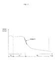
- Figure 1 is a plot of sensor output against time during operation of a conventional microwave oven.
- the cooling of a cooking chamber is performed for an initial waiting time TC of about twenty seconds at the first stage of a cooking operation.
- a first cooking time T1 is the period from the end of the initial waiting time TC until the coincidence of the slope of the sensor output with a preset reference slope A.
- a second cooking time T2 is set on the basis of the first cooking time and a factor, preset according to the kind of food. Cooking is complete at end of the second cooking time.
- the transition between the first cooking time T1 and the second cooking time T2 is based on the output of a humidity sensor, specifically a curve representative of the humidity percentage detected over time.
- the conventional system determines when slope A has been met, based on a detection of when a sampled humidity exceeds a predetermined amount. This predetermined amount had been determined, through experimentation, to be typically the point along the curve where an abrupt change occurs, ideally at the slope A position, for a particular food.
- a factory predetermined humidity level representative of an ideal point of abrupt change along such a curve will not typically match a real world point of abrupt change along a similar curve.
- the cooling of the cooking chamber is performed by operating only a fan for the initial waiting time at the first stage of a cooking operation.
- the entire cooking time is lengthened and the power consumption of the microwave oven is increased.
- an accurate control of the cooking operation becomes difficult because the control of the cooking operation is performed by detecting the slope of the output value curve of a sensor.
- a more accurate control of the cooking operation is needed.
- a microwave oven according to the present invention is characterised in that the controller is configured to repeatedly calculate the difference between the respective sums of sampled sensor values in two adjacent moving windows and determine said transition point on the basis of the magnitude of said difference.
- the environmental sensor is a humidity sensor.
- the controller is configured to determine said transition point by comparing said difference with a threshold value.
- the controller is configured to determine the length of the first period by timing from the start of a cooking operation to said transition and set the duration of the second cooking period on the basis of the duration of the first period.
- a microwave oven includes a body 1 provided with a cooking chamber 2 and an electrical component compartment 3, a cooking chamber door 4 hingedly attached to the body 1, a control panel 5 having an input unit with a plurality of buttons (not shown) and a display unit for displaying information and a humidity sensor 6 for detecting the humidity of the air in the cooking chamber 2.
- the cooking chamber 2 is constructed to be open at its front.
- a turntable 2a is located at the bottom of the cooking chamber 2.
- An air inlet 7a is formed through a front portion of one sidewall 7 of the cooking chamber putting the cooking chamber 2 in communicate with the electrical component compartment 3 and allowing outside air to flow into the cooking chamber 2.
- An air outlet 8a is formed through a rear portion of the other sidewall 8 of the cooking chamber to allow air to be exhausted from the cooking chamber 2 to the outside.
- a magnetron 3a for generating high-frequency waves, a cooling fan 3b for sucking outside air and cooling electric devices, and an air guide duct 3c for guiding the flow of air from the electrical component compartment 3 toward the air inlet 7a are mounted in the electrical component compartment 3.
- the cooling fan 3 is disposed between the magnetron 3a and the rear wall of the electrical component compartment 3.
- a plurality of air suction holes 3d are formed through the rear wall of the electrical component compartment 3 to allow outside air to flow into the microwave oven.
- the humidity sensor 6 is mounted on the outer surface of the second sidewall of the cooking chamber 2 facing the air outlet 8a so as to be situated in the path of air being discharged from the cooking chamber 2. Accordingly, the humidity sensor 6 is capable of detecting the humidity of air being discharged from the cooking chamber 2 through the air outlet 8a.
- the humidity sensor 6 is electrically connected to a circuit board (not shown) enclosed in the control panel 5.
- the microwave oven includes a control unit 11 for controlling the entire operation of the microwave oven.
- the input unit 5a is mounted in the control panel 5, receives operational commands from a user, is electrically connected to the control unit 11, and transmits to the control unit 11 signals generated by inputs from a user.
- the humidity sensor 6, which detects the humidity formed during cooking, and a temperature sensor 9 are electrically connected to the control unit 11.
- a data storage unit 10 is also connected to the control unit 11.
- a magnetron drive unit 12a for operating the magnetron 3a, a fan drive unit 12b for driving the cooling fan 3b, a motor drive unit 12c for driving a motor to rotate the turntable 2a and a display drive unit 12d for operating the display unit 5b, provided in the control panel 5, to display operational state information and alarms, are all be connected to the control unit 11.
- the control unit 11 controls the magnetron drive unit 12a to operate the magnetron 3a. According to this control, high-frequency waves generated by the magnetron 3a irradiate the cooking chamber 2 and cook the food.
- the control unit 11 controls the magnetron 3a, the motor 2b, and the cooling fan 3b to cook the food, based on the detection signals transmitted from the humidity sensor 6.
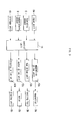
- a user initially sets cooking conditions through the input unit 5a, provided in the control panel 5 (S10).
- the control unit 11 determines whether a cooking start command has been input through the input unit 5a (S20). If the cooking start command has been input, the control unit 11 controls the magnetron drive unit 12a to operate the magnetron 3a for the generation of high-frequency waves and the fan drive unit 12b to operate the cooling fan 3b. Additionally, the control unit 11 controls the motor drive unit 12c to operate the motor 3b for the rotation of the turntable 2a. Meanwhile, the control unit 11 accumulates the cooking time (S30).
- control unit 11 samples the output signal of the humidity sensor 6 at 0.5 second intervals (S40). The samples are stored and the control unit 11 accumulates sampled humidity values in adjacent windows, l to m and m+1 to n, of the same length and stores them in the data storage unit 10.
- control unit 11 determines whether the magnitude of the difference ⁇ K between K m and K n , i.e.
- the control unit 11 sets T1 to be the current time (S70). Thereafter, the control unit 11 calculates a second cooking time T2 on the basis of the first cooking time T1 and a factor preset according to the kind of food (S80).
- the control unit 11 determines whether the second cooking time T2 has elapsed (S90). If the second cooking time T2 has elapsed, the control unit 11 controls the magnetron drive unit 12a to stop the magnetron 3a, the fan drive unit 12b to stop the fan 3b and the motor drive unit 12 to stop the motor 2b, thereby finishing the cooking operation (S100).
- the output values of the humidity sensor 6 are sampled at certain predetermined times, e.g. periods ⁇ Ts, and the sampled humidity values are accumulated.
- a first cooking time T1 is determined as the time from the start of the cooking operation until ⁇ K is greater than or equal to the preset reference value.
- a second cooking time T2 is calculated by multiplying the first cooking time T1 by a factor preset according to the kind of food. The cooking operation is completed after the second cooking time T2 is elapsed.
- the point at which an abrupt change in slope occurs along a sensor output curve, such as in Figure 1 is representative of the preferred moment of transition between the first cooking time T1 and the second cooking time T2.
- this abrupt change is detected by calculating the difference between two samples.
- the difference between two samples equals or exceeds a preset reference value, inherently the slope between the two samples has also equaled or exceed a predetermined amount, which is representative of the abrupt change.
- embodiments of the present invention could also include the detection of such abrupt changes using more than two sample points and/or alternative methodologies, e.g., such as through using polynomials or interpolation.
- the output values of the humidity sensor 6 are sampled at certain periods, and a time when the absolute value of the difference between the current sampled humidity value sum and preceding sampled humidity value sum of the output values of the humidity sensor 6 is equal to the preset reference value is detected.
- an embodiment of the present invention provide a microwave oven control method and apparatus, in which the outputs of a humidity sensor are sampled at certain periods, the sampled humidity values are accumulated, and a time when the absolute value of the difference between the current sampled humidity value sum and preceding sampled humidity value sum of the output values of the humidity sensor is equal to the preset reference value is detected. Accordingly, the cooking control of the microwave oven can be accurately carried out by reducing an error due to sequential cooking operations, and the power consumption of the microwave oven can be reduced due to the elimination of the cooling of a cooking chamber.
Landscapes
- Physics & Mathematics (AREA)
- Electromagnetism (AREA)
- Electric Ovens (AREA)
- Control Of High-Frequency Heating Circuits (AREA)
Applications Claiming Priority (2)
| Application Number | Priority Date | Filing Date | Title |
|---|---|---|---|
| US5366 | 2001-12-07 | ||
| US10/005,366 US6538240B1 (en) | 2001-12-07 | 2001-12-07 | Method and apparatus for controlling a microwave oven |
Publications (2)
| Publication Number | Publication Date |
|---|---|
| EP1318698A2 true EP1318698A2 (de) | 2003-06-11 |
| EP1318698A3 EP1318698A3 (de) | 2005-09-07 |
Family
ID=21715489
Family Applications (1)
| Application Number | Title | Priority Date | Filing Date |
|---|---|---|---|
| EP02253570A Withdrawn EP1318698A3 (de) | 2001-12-07 | 2002-05-21 | Mikrowellenofen mit Zustandssensor und das Verhalten des Sensors |
Country Status (5)
| Country | Link |
|---|---|
| US (1) | US6538240B1 (de) |
| EP (1) | EP1318698A3 (de) |
| JP (1) | JP3977141B2 (de) |
| KR (1) | KR100576619B1 (de) |
| CN (1) | CN1277069C (de) |
Families Citing this family (15)
| Publication number | Priority date | Publication date | Assignee | Title |
|---|---|---|---|---|
| KR100485347B1 (ko) * | 2002-04-04 | 2005-04-27 | 삼성전자주식회사 | 전자렌지 및 그 제어방법 |
| ITVA20030046A1 (it) * | 2003-12-04 | 2005-06-05 | Whirlpool Co | Forno domestico e procedimento di cottura che lo utilizza. |
| US7461588B2 (en) * | 2004-08-31 | 2008-12-09 | General Electric Company | Methods and apparatus for operating a speedcooking oven |
| KR100598403B1 (ko) * | 2004-11-17 | 2006-07-07 | 삼성전자주식회사 | 전자렌지 및 그 제어 방법 |
| US9801238B2 (en) * | 2012-05-30 | 2017-10-24 | Acp, Inc | Dynamic control system for a magnetron tube in a microwave oven |
| CN103575069B (zh) * | 2012-08-02 | 2015-08-05 | 广东美的厨房电器制造有限公司 | 微波炉及其烘干控制方法 |
| US20170071393A1 (en) * | 2014-03-11 | 2017-03-16 | Koninklijke Philips N.V. | Method and apparatus for controlling a cooking process of a food |
| CN105351985B (zh) * | 2015-12-16 | 2017-11-07 | 广东美的厨房电器制造有限公司 | 微波炉的控制方法及控制装置 |
| CN108255080B (zh) * | 2016-12-29 | 2020-08-25 | 佛山市顺德区美的电热电器制造有限公司 | 自定义烹饪曲线的方法、系统及终端 |
| CN108696955B (zh) * | 2017-04-10 | 2021-10-26 | 佛山市顺德区美的电热电器制造有限公司 | 用于电烹饪器的锅具干烧判断方法、装置和电烹饪器 |
| CN108732958B (zh) * | 2017-04-18 | 2020-06-05 | 佛山市顺德区美的电热电器制造有限公司 | 电烹饪器及其烹饪控制方法和装置 |
| CN109798543B (zh) * | 2018-12-30 | 2020-12-29 | 佛山市顺德区美的洗涤电器制造有限公司 | 灶具的火力控制方法、装置、灶具及存储介质 |
| CN111966153B (zh) * | 2020-07-17 | 2023-03-14 | 华帝股份有限公司 | 一种氧传感器的控制方法 |
| KR102959323B1 (ko) * | 2021-05-12 | 2026-04-29 | 엘지전자 주식회사 | 조리기기 및 그 제어방법 |
| CN115462677B (zh) * | 2022-09-14 | 2024-09-17 | 宁波方太厨具有限公司 | 烹饪设备的控制方法、系统、烹饪设备和存储介质 |
Family Cites Families (10)
| Publication number | Priority date | Publication date | Assignee | Title |
|---|---|---|---|---|
| US4097707A (en) * | 1975-05-20 | 1978-06-27 | Matsushita Electric Industrial Co., Ltd. | Apparatus for controlling heating time utilizing humidity sensing |
| JPS5261850A (en) * | 1975-11-17 | 1977-05-21 | Matsushita Electric Ind Co Ltd | Timer for range |
| AU498357B2 (en) * | 1976-02-17 | 1979-03-08 | Matsushita Electric Industrial Co., Ltd. | Heating control apparatus |
| JPS60196521A (ja) * | 1984-03-16 | 1985-10-05 | Mitsubishi Electric Corp | 加熱調理器 |
| US4864088A (en) * | 1987-07-03 | 1989-09-05 | Sanyo Electric Co., Ltd. | Electronically controlled cooking apparatus for controlling heating of food using a humidity sensor |
| JP2898716B2 (ja) * | 1990-07-30 | 1999-06-02 | 株式会社東芝 | 加熱調理装置 |
| US5349163A (en) * | 1990-08-17 | 1994-09-20 | Samsung Electronics Co., Ltd. | Method of automatically cooking food by detecting the amount of gas or smoke being exhausted from a cooking device during cooking |
| KR920005668A (ko) * | 1990-08-17 | 1992-03-28 | 강진구 | 전자레인지의 자동 조리방법 |
| GB2293027A (en) * | 1994-09-07 | 1996-03-13 | Sharp Kk | Apparatus for and method of controlling a microwave oven |
| KR0146126B1 (ko) * | 1994-12-16 | 1998-08-17 | 구자홍 | 전자레인지의 가열시간 제어장치 및 방법 |
-
2001
- 2001-12-07 US US10/005,366 patent/US6538240B1/en not_active Expired - Lifetime
-
2002
- 2002-03-05 KR KR1020020011505A patent/KR100576619B1/ko not_active Expired - Fee Related
- 2002-05-15 CN CNB021198586A patent/CN1277069C/zh not_active Expired - Fee Related
- 2002-05-17 JP JP2002143735A patent/JP3977141B2/ja not_active Expired - Lifetime
- 2002-05-21 EP EP02253570A patent/EP1318698A3/de not_active Withdrawn
Also Published As
| Publication number | Publication date |
|---|---|
| KR20030047645A (ko) | 2003-06-18 |
| EP1318698A3 (de) | 2005-09-07 |
| JP3977141B2 (ja) | 2007-09-19 |
| CN1277069C (zh) | 2006-09-27 |
| KR100576619B1 (ko) | 2006-05-08 |
| CN1423091A (zh) | 2003-06-11 |
| JP2003172516A (ja) | 2003-06-20 |
| US6538240B1 (en) | 2003-03-25 |
Similar Documents
| Publication | Publication Date | Title |
|---|---|---|
| JP4072579B2 (ja) | 電子レンジ及びその制御方法 | |
| US6538240B1 (en) | Method and apparatus for controlling a microwave oven | |
| US7923664B2 (en) | Method for controlling a cooking process in a cooking appliance | |
| US5545881A (en) | Heating time control apparatus and method thereof for microwave oven | |
| EP0576145A1 (de) | Kochvorrichtung mit Gassmesswertgeber | |
| US6670591B2 (en) | Microwave oven | |
| US6093922A (en) | Wall mounted microwave oven and control method therefor | |
| KR100288935B1 (ko) | 전자레인지의 자동조리제어방법 | |
| KR20060122128A (ko) | 전자레인지의 쿨링시간 제어장치 및 그 방법 | |
| EP1353535B1 (de) | Verfahren und Vorrichtung zur Steuerung eines Mikrowellenofen | |
| KR100215036B1 (ko) | 전자 렌지의 해동 장치 및 그 해동 방법 | |
| KR100485571B1 (ko) | 전자레인지의 제어 장치 및 방법 | |
| KR100377722B1 (ko) | 전자레인지의 자동조리제어방법_ | |
| KR0133435B1 (ko) | 마이크로웨이브오븐의 자동조리 장치 및 방법 | |
| KR101182456B1 (ko) | 전자레인지의 제어방법 | |
| KR0146131B1 (ko) | 마이크로웨이브오븐의 자동조리 장치 및 방법 | |
| JP2001173961A (ja) | 電子レンジ | |
| EP0234843A1 (de) | Heizapparat | |
| KR20050058066A (ko) | 조리 장치 및 그 제어 방법 | |
| JP2534763B2 (ja) | 電子レンジ | |
| KR0161090B1 (ko) | 그릴 전자레인지의 자동 요리 장치 및 그 방법 | |
| JPH09119649A (ja) | 電子レンジ | |
| JP2002181336A (ja) | 電子レンジ | |
| JPH10223366A (ja) | 加熱装置 |
Legal Events
| Date | Code | Title | Description |
|---|---|---|---|
| PUAI | Public reference made under article 153(3) epc to a published international application that has entered the european phase |
Free format text: ORIGINAL CODE: 0009012 |
|
| AK | Designated contracting states |
Designated state(s): AT BE CH CY DE DK ES FI FR GB GR IE IT LI LU MC NL PT SE TR |
|
| AX | Request for extension of the european patent |
Extension state: AL LT LV MK RO SI |
|
| RAP1 | Party data changed (applicant data changed or rights of an application transferred) |
Owner name: SAMSUNG ELECTRONICS CO., LTD. |
|
| PUAL | Search report despatched |
Free format text: ORIGINAL CODE: 0009013 |
|
| AK | Designated contracting states |
Kind code of ref document: A3 Designated state(s): AT BE CH CY DE DK ES FI FR GB GR IE IT LI LU MC NL PT SE TR |
|
| AX | Request for extension of the european patent |
Extension state: AL LT LV MK RO SI |
|
| 17P | Request for examination filed |
Effective date: 20060110 |
|
| AKX | Designation fees paid |
Designated state(s): DE FR GB |
|
| GRAP | Despatch of communication of intention to grant a patent |
Free format text: ORIGINAL CODE: EPIDOSNIGR1 |
|
| STAA | Information on the status of an ep patent application or granted ep patent |
Free format text: STATUS: THE APPLICATION IS DEEMED TO BE WITHDRAWN |
|
| 18D | Application deemed to be withdrawn |
Effective date: 20081201 |