EP1318965B1 - Machine de transbordement de materiau - Google Patents
Machine de transbordement de materiau Download PDFInfo
- Publication number
- EP1318965B1 EP1318965B1 EP01982312A EP01982312A EP1318965B1 EP 1318965 B1 EP1318965 B1 EP 1318965B1 EP 01982312 A EP01982312 A EP 01982312A EP 01982312 A EP01982312 A EP 01982312A EP 1318965 B1 EP1318965 B1 EP 1318965B1
- Authority
- EP
- European Patent Office
- Prior art keywords
- superstructure
- substructure
- lowered
- goods transhipment
- connecting rod
- Prior art date
- Legal status (The legal status is an assumption and is not a legal conclusion. Google has not performed a legal analysis and makes no representation as to the accuracy of the status listed.)
- Expired - Lifetime
Links
- 239000000463 material Substances 0.000 title abstract description 57
- 230000000284 resting effect Effects 0.000 claims abstract description 3
- 238000012423 maintenance Methods 0.000 description 6
- 210000000078 claw Anatomy 0.000 description 4
- XLYOFNOQVPJJNP-UHFFFAOYSA-N water Substances O XLYOFNOQVPJJNP-UHFFFAOYSA-N 0.000 description 4
- 229910000831 Steel Inorganic materials 0.000 description 2
- 238000005461 lubrication Methods 0.000 description 2
- 239000010959 steel Substances 0.000 description 2
- 239000000758 substrate Substances 0.000 description 2
- 239000010426 asphalt Substances 0.000 description 1
- 230000000903 blocking effect Effects 0.000 description 1
- 230000001419 dependent effect Effects 0.000 description 1
- 208000028659 discharge Diseases 0.000 description 1
- 230000000694 effects Effects 0.000 description 1
- 230000005484 gravity Effects 0.000 description 1
- 230000000750 progressive effect Effects 0.000 description 1
- 239000004576 sand Substances 0.000 description 1
- 239000002023 wood Substances 0.000 description 1
Images





Classifications
-
- B—PERFORMING OPERATIONS; TRANSPORTING
- B66—HOISTING; LIFTING; HAULING
- B66C—CRANES; LOAD-ENGAGING ELEMENTS OR DEVICES FOR CRANES, CAPSTANS, WINCHES, OR TACKLES
- B66C23/00—Cranes comprising essentially a beam, boom, or triangular structure acting as a cantilever and mounted for translatory of swinging movements in vertical or horizontal planes or a combination of such movements, e.g. jib-cranes, derricks, tower cranes
- B66C23/54—Cranes comprising essentially a beam, boom, or triangular structure acting as a cantilever and mounted for translatory of swinging movements in vertical or horizontal planes or a combination of such movements, e.g. jib-cranes, derricks, tower cranes with pneumatic or hydraulic motors, e.g. for actuating jib-cranes on tractors
-
- B—PERFORMING OPERATIONS; TRANSPORTING
- B66—HOISTING; LIFTING; HAULING
- B66C—CRANES; LOAD-ENGAGING ELEMENTS OR DEVICES FOR CRANES, CAPSTANS, WINCHES, OR TACKLES
- B66C23/00—Cranes comprising essentially a beam, boom, or triangular structure acting as a cantilever and mounted for translatory of swinging movements in vertical or horizontal planes or a combination of such movements, e.g. jib-cranes, derricks, tower cranes
- B66C23/62—Constructional features or details
Definitions
- the present invention relates to a material handling device having the features of the preamble of claim 1.
- Such material handling equipment find their use mainly in inland ports and their adjacent storage areas for the handling of different materials, such as wood, scrap, gravel, sand and the like.
- Material handling equipment are powerful, flexible loading machines with a long reach (at least 18 to 20 meters reach) and fast working cycles with large grippers, magnetic disks or the like.
- the requirements for these loading machines in terms of flexibility consist on the one hand in terms of use on work on the quay for unloading the ship both high and low water and on the other hand in a fast moving the loading machine to another unloading or to a storage space or the also further (10 to 50 km) can be removed.
- stationary loading machines or port cranes which are installed on a steel or concrete pier at a height of about 4 to 7 meters.
- quasi-stationary harbor cranes are known, which are arranged movable along the quay on rails.
- mobile handling equipment on caterpillar or wheel drives are known as self-propelled short distances (up to 5 km distance) are profitable. In case of dislocation distances exceeding the said short distance, loading takes place on low loaders. The latter handling equipment is subject in its dimensions in the loading height the given limits through vertical heights of bridges, etc.
- a material handling device is known from the prior art, which has a particular mobile undercarriage on which the superstructure with the driver's cab, engine compartment and boom by means of a tubular pylon (steel column) is arranged at a height of 4 to 6 meters.
- the known material handling equipment is particularly suitable for use in ship unloading in port handling and space work, but has the disadvantage that it must be built in place and by Eigenforthogany in very limited distances of a maximum of 2 to 4 kilometers - if no bridges, Power lines or the like are in the way - is movable.
- Another disadvantage of the known material handling device is that the maintenance, lubrication, refueling, etc.
- GB-A-1 374 253 discloses a material handling apparatus according to the preamble of claim 1.
- the material handling device has a mobile undercarriage with an engine compartment, a superstructure rotatably arranged with respect to the undercarriage with a driving cab, and a jib or a jib system articulated on the superstructure.
- the superstructure is formed between a sub-position (rest position) on the undercarriage and a top position (working position) spaced from the undercarriage adjustable.
- the adjusting device for adjusting the superstructure located between a superstructure and undercarriage handlebar assembly is provided with actuating cylinder.
- This measure increases the flexibility of a material handling device as by adjusting the position of the superstructure between a lower and an upper position on the one hand a sufficiently high arrangement of the boom and thus all requirements for range, depth of loading and Kochladeanno of shipborders are met, on the other hand in the lowered position on the undercarriage improves the own mobility and a transport on low loaders is made possible.
- operating personnel in the lowered state of the superstructure can be comfortable get on the cab located on the superstructure, and the refueling, maintenance of the engine room, etc. is also easier in the lowered state.
- the material handling device further comprises a provided on the undercarriage wheel drive with at least two axles, wherein at least two lowerable support members are provided for supporting the material handling device in the operating state and the removal of the axles of the Oberwagenmosachse in the operating state at least the distance of a given by the lowered support elements tipping line corresponds to the axis of rotation.
- the distance between the wheel axles to the axis of rotation of the upper carriage extending perpendicular thereto is thus greater than or equal to the distance between a tilted line spanned by the lowered support elements and the axis of rotation.
- the ideal tipping line corresponds to a circle around the axis of rotation, the radius of which corresponds to the support length from the longitudinal axis (center line) of the undercarriage to the support edge.
- the requirement for the dimensioning of the material handling device according to the invention thus consists in that in any position of the 360 ° comprehensive pivoting of the superstructure, the tipping lines may distinguish the described tilting circle.
- two lowerable support elements are provided, which are arranged between the two wheel axles of a material handling device with wheel drive.
- four lowerable support members are provided, of which a first pair is arranged on the front side of the undercarriage and a second pair between the two wheel axles.
- a partially lowered position on the undercarriage is provided as a driving position, while the actual rest position for transport on a low loader, for maintenance, refueling, entry / exit of operating personnel represents a fully lowered position.
- the material handling device is configured such that a vertical axis of rotation of the upper carriage in the upper position (working position) extends approximately through the center of the undercarriage in caterpillar drive or through the center of the supports of the undercarriage in wheel drive to work, in particular when turning the superstructure, to achieve the same level of stability on all sides.
- the adjustment of the upper carriage relative to the undercarriage by means of an intermediate superstructure and undercarriage handlebar assembly with adjusting cylinder is a mechanically simple, but reliable and statically stable implementation of the inventive idea described above.
- an embodiment of the handlebar assembly proves to be a parallel link, which is hinged on the one hand on the undercarriage and on the other hand to a substructure of the superstructure.
- the substructure of the superstructure is provided as a kind of intermediate frame to which the links of the linkage arrangement are articulated and on which the superstructure is rotatably mounted via a pivot bearing.
- an adjusting device for height adjustment of the superstructure engages directly on the uppercarriage and is articulated at the lower end to an intermediate frame, which is rotatably arranged relative to the undercarriage.
- the parallel links of the adjusting device representing linkage arrangement are preferably designed as a 4-point link, whereby the combination is possible that one of the links is a 3-point link, the other is a 4-point link.
- a particularly advantageous embodiment of the invention is a lowering of the upper carriage in the sub-position by pivoting the parallel link to the rear of the material handling device out.
- the superstructure is lowered into a position in which it comes to lie above the rear region of the material handling device, which makes it possible to fold the boom extending in the direction of the front region of the material handling device over the front area of the material handling device and there at the lowest possible height extension for the rest of the material handling device. and loading position.
- the motor space arranged on the superstructure comes to rest in a position located behind the undercarriage, in which it is directly accessible from several sides, whereby maintenance, refueling and the like are greatly simplified.
- the articulated in the rear area parallel link is articulated deeper than the hinged in the front area parallel links, and the hinged at the rear of the parallel link is hinged to the superstructure on an obliquely downwardly projecting portion of the superstructure undercarriage.
- the obliquely downwardly projecting portion of the superstructure undercarriage is oriented on the geometry of the undercarriage and designed such that it in the lowered sub-position of the upper carriage when resting or supporting a front horizontal portion of the substructure on the undercarriage behind the rear of the undercarriage to the ground (Road level) is sufficient, thereby causing maximum support and relief of the parallel links.
- steps can be formed or attached to the obliquely downwardly projecting portion of the upper body substructure, providing a comfortable entry from operating personnel to the superstructure or the driver's cab.
- the undercarriage on a caterpillar drive is a telescopic crawler undercarriage whose track width is adjustable.
- a telescopic crawler drive is known from DE 93 19 382 U1.
- the inclination angle of the parallel links in the upper position between about 0 ° and about 20 ° to the vertical.
- Particularly advantageous is an inclination angle to the vertical of about 15 °.
- the parallel link which is articulated in the rear region, advantageously has a cranked shape, so that in the lowered sub-position it bridges the wheel axle arranged in the rear region.
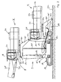
- FIG. 1 shows a first exemplary embodiment of a material handling device 1 according to the invention.
- the material handling device 1 (hereinafter referred to simply as a charger for short) comprises a crawler-type undercarriage 10 and a superstructure 20.
- a driver's cab 21, an engine compartment 22, a space 23 for hydraulics and a rear weight 24 comprising uppercarriage 20 is mounted by means of a pivot bearing 27 on a substructure 30 (see also Figure 2, which shows the charger 1 according to the invention in a partial side view).
- a boom 25 with loading handle 28 and gripper 29 is hinged to the boom 20 on a boom bearing axis 8.
- the cantilever system shown for example, with more or less joint parts or telescopic boom combinations, find use.
- the superstructure 20 is arranged at a height of approximately 5 to 6 meters at a distance from the undercarriage 10.
- the spaced arrangement is achieved by a link assembly 9, by means of which the superstructure 20 according to the invention can be lowered into a sub-position on the undercarriage 10.
- Figure 1 illustrates the possible applications of a charger according to the invention using the example of a use in port handling on a quay wall 2.
- the hull 4 In front of the quay wall 2 is a cargo ship, the hull 4 is schematically shown with cargo 5 in section. At low water level 3 and fully loaded the side wall of the hull 4 is approximately at the same height with the quay wall 2. At maximum water level 6 against it (and in particular with progressive discharge), the hull is raised to the dot-dash line position 7.
- the boom support 8 (cf., FIG. 2) must be arranged sufficiently high above the quay wall 2. From the meter grid stored in the drawing can be read for this purpose a height of about 6 meters. The eye level of the operator must be at a similar level for reasons of clarity.
- the handlebar assembly 9 comprises a parallel link 16, 18.
- the two parallel link forming the parallel links 16, 18 are articulated at their lower ends to a chassis center body 11 of the undercarriage 10 and with their upper ends to the base 30 of the upper carriage 20.
- a first parallel link 16, which is a so-called 4-point link (see Figure 3) is articulated in a front region of the undercarriage 10 on a front link shaft 15 on the center body 11, while a second parallel link 18, at which is a so-called 3-point link (see Figure 4), is hinged to the rear body of the undercarriage 10 on a rear link shaft 17 on the center body 11.
- the two parallel links 16, 18 are the same length, but articulated to improve the pivot geometry in particular with regard to the position of the handlebar and the upper carriage in the lowered position at different heights on the center body 11.
- the superstructure is lowered by pivoting the parallel links 16, 18 toward the rear of the undercarriage 10 out. For this reason, the front parallel link 16 is higher and the rear parallel link 18 hinged deeper.
- the substructure 30 has two sections for this purpose, namely, a first horizontally extending portion 36, on which the pivot bearing is provided for fully soumosbaren arrangement of the upper carriage, and a second portion 35 which extends obliquely downward towards the rear of the charger 1.
- the front parallel link 16 is hinged to a front substructure handlebar axis 31 at the horizontal portion 36 and the rear parallel link 18 to a rear substructure handlebar axis 32 at the cantilevered portion 35.
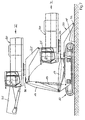
- the obliquely downwardly extending (abkragende) portion 35 of the uppercarriage substructure 30 is formed in its geometry such that the different height in the articulation of the two parallel links 16, 18 is compensated. Furthermore, the link assembly 9 is designed such that - as shown in Figure 2 - in the lowered position I of the upper carriage 20, the parallel links 16, 18 rest on the undercarriage 19 and the ground (road surface) 37, wherein the end of the abkragenden Section 35 of the uppercarriage substructure 30 in the region of the pivot axis 32 on the substrate 37 rests supporting.
- a Stellzylindercru 19 front parallel link 16 is formed as a 4-point handlebar with maximum width to turn and To initiate tipping forces from the intermediate frame of the uppercarriage substructure 30 into the chassis centerbody 11.
- the hinged in the rear area second, non-powered handlebar 18 is advantageously designed as a 3-point handlebars so that it engages the base 30 at a point (handlebar axis 32) to those of components of this size (the handlebar length is about 3 to 3.50 m) to compensate occurring length tolerances.
- FIGS. 3 and 4 show the charger 1 according to the invention in a front view (FIG. 3) or in a rear view (FIG. 4).
- the arrangement of the caterpillar drive of the undercarriage 10 with caterpillars 13, 14 can be seen.
- the caterpillar drive is preferably a telescopic by means of telescopic guides 12 caterpillar drive, so that the caterpillars 13, 14 are adjustable in the track width, creating an adjustment between a space-saving transport condition (transport width T) and an increased stability conferring working condition (working width A) is possible (see Figure 4).
- the transport position of the crawler vessels 13, 14 is shown by dashed lines in Figures 3 and 4.
- the representation of the telescopic guides 12 is purely schematic, and also a further detailed description of the telescopic adjustment of the crawler vessels 13, 14 is omitted, since it is known per se from the prior art.
- the front parallel link 16 preferably has a recess 33 (compare Figures 3 and 4), which contributes to weight savings and creates space for from the uppercar 20 to the undercarriage 10 extending hose lines 34 (see Figure 2).
- a step ladder 40 as shown in FIGS. 4 and 5 may be provided which are arranged on the uppercarriage 20, more precisely on the undercarriage 30 of the uppercarriage 20 is that it comes to lie in the lowered state (sub-position I) with its lowest tread a little above the ground 37. It proves to be particularly advantageous, the Steep ladder 40 ausschiebbar makeup Kunststoffer so that it is analogous to the telescopic crawler between the above working position and not on the outer dimensions of the superstructure laterally projecting transport position is displaced (see Figure 4). However, the approach of operators can also be done on the caterpillar 13, if no step ladder is provided.
- FIG. 5 shows the inventive charging device 1 of FIG. 1 in a lateral overall view in the sub-position I, which represents the training and entry position for the operator and the maintenance position for refueling, lubrication, etc.
- the sub-position I of the charger 1 according to the invention in loading position with folded-in boom for a so-called Tiefbett truck is also shown in Figure 6 in a general side view.
- the boom 25 is lowered and folded so far with the charging handle 28 that it does not project beyond the roof of the driver's cab 21 at its highest point and does not exceed a height of about 3.70 m.
- the crawler undercarriage retracted to transport width T.
- FIG. 7 shows a further exemplary embodiment of a charging device according to the invention, in which, unlike the first exemplary embodiment shown in FIGS. 1 to 6, the parallel links 16, 18 in the upper position II of the upper carriage 20 are not vertical but have a slight inclination in the direction of the rear end of the upper carriage Charger stand. In the illustrated embodiment, this inclination is about 15 °.
- control of the charger is preferably such that a (full) pivoting of the superstructure 20 about the vertical axis 27 is released only when the superstructure 20 has reached its working position and the two caterpillars 13, 14 in their extended working width are located so that a sufficient stability is ensured. If the undercarriage has a wheel drive, so would analogously the rotation of the upper carriage released only when appropriate legs are extended to improve stability.
- a driving position III of the upper carriage shown in Figure 8 may be provided, in which the obliquely downwardly projecting portion 35 of the uppercarriage substructure 30 does not rest on the ground 37, but is located approximately at the level of the upper edge of the caterpillars 13, 14.
- the charger can be driven with its own drive (blocking the turning of the superstructure) to keep the height and center of gravity of the whole unit low in difficult terrain or under bridges.
- FIG 9 shows a further embodiment of an inventive material handling device with wheel drive.
- the wheel drive of the material handling apparatus comprises two wheel axles 50, 51, namely a live axle 50 arranged in the rear region of the undercarriage 10 'and a pendulum axle 51 arranged in the front region of the undercarriage 10'.
- the material handling device comprises on the undercarriage 10 'fixed Pratzenabstützungen 60, 64, of which a first pair 60 on the front side of the undercarriage 10' and a second pair 64 between the two wheel axles 50, 51 is arranged.
- the distances and dimensions are selected such that at least one of the axles (in the illustrated embodiment, the rear rigid axle 50) at a distance from the upper carriage rotation axis in the operating state, ie in the upper position II, which is greater than or equal to the distance of a tilting line K of the Upper carriage axis of rotation 70 is (see also Figure 11).
- the ideal tipping line is an imaginary circle X about the axis of rotation 70 of radius R corresponding to the support length from the center line (longitudinal axis) of the undercarriage to the tipping line K defined by the lowered support braces.
- the tipping lines K may undercut the tilting circle X.
- FIG. 10 shows, as a similar exemplary embodiment, a further material handling device with wheel drive, which has a longer wheelbase between the two wheel axles 50, 51 and has only one pair of brackets 64 for support, which is arranged between the two wheel axles 50, 51.
- the arrangement is such that the distance between the two wheel axles 50, 51 to the axis spanned by the two claws 61 greater than or equal to the radius R, as defined above, corresponds (see also Figure 12).
- the described arrangements achieve a stability of the material handling device which is just in line with the adjustment of the superstructure between a sub-position I and a top position II.
- the described undercarriages with wheel drive are especially necessary when the material handling device on with Teerbelag, paving, asphalt or similar. fixed ground, which could be damaged by a caterpillar drive. Especially in urban demolition or demolition projects caterpillars would cause too much damage on roads or paved squares.
- the material handling devices according to the invention have a secure all-round support for such applications.
- the parallel link 18 '(so-called triangular link) articulated in the rear region of the undercarriage 10' is designed with a crank, such that the wishbone 18 'in the lowered sub-position bridges the wheel axle 50 located in the rear region and preferably rests with its end remote from the vehicle on the ground, whereby a support is achieved.
- Figure 13 shows a front view of a Pratzenabstütz issued 60 with two lowerable claws 61, which rest by means of bottom plates 62 on the substrate 62 and thus allow a support of the material handling device.
- the claws 61 are located within the transport width of the material handling device given by the wheels 66.
- support cylinders 63 (see FIG. This pressure limitation prevents that in the embodiment of Figure 9, the rigid axle 50 and in the embodiment of Figure 10, the two axes 50, 51 lift off the ground and as (additional) support element in the operating state are not available. This is particularly important because when lifting the axle (s) this would no longer act as a crease line (s).
- the illustrated Pratzenabstützache can also be replaced by so-called telescopic supports, extend the vertical hydraulic punch to the dimension R (or larger).
- Figure 14 shows a support of a wheel-driven undercarriage for a material handling device, in which the superstructure 20 is arranged directly on the undercarriage 10 " is. Again, it is achieved by the arrangement that both wheel axles 50, 51 act as support elements.
- Figure 15 shows the top view of the undercarriage of the material handling device of Figure 14.
- a per se hydraulic Pendelachsverriegelung 54 shown, which is connected such that only after supporting and locking the pendulum axis 51 by the pendulum axle locking the work functions be released in the superstructure.
- the support and axle lock can be controlled by simple pressure sensors.
- an equipment with Radunterwagen is provided, which can be realized with commercial heavy-duty axles and in which the required all-round safety is achieved by including support means including one or more axles as support means.
- the function of the lowerable supporting elements can be replaced by the wheel axles and the wheels, provided that the wheel axles are widened so far that the wheels form a quadrangle completely outside the tilting circle X. form.
- a wheel-driven material handling device can be formed without additional support elements. Such an embodiment is shown in plan view of the undercarriage in Figure 16.
Landscapes
- Engineering & Computer Science (AREA)
- Mechanical Engineering (AREA)
- Jib Cranes (AREA)
- Forklifts And Lifting Vehicles (AREA)
Abstract
Claims (14)
- Engin de transbordement de matériaux comportant une structure inférieure (10) mobile, une structure supérieure (20) agencée mobile en rotation par rapport à la structure inférieure (10) et pourvue d'une cabine de chauffeur (21) et d'une flèche ou d'un système à flèche (25) articulé(e) sur la structure supérieure (20), dans lequel- la structure supérieure (20) est déplaçable entre une position inférieure (position de repos I) sur la structure inférieure (10) et une position supérieure (position de travail II) à distance de la structure inférieure (10),- il est prévu, à titre de dispositif de déplacement pour déplacer la structure supérieure (20), un agencement à bras (9) situé entre la structure supérieure (20) et la structure inférieure (10, 10', 10") et comportant un vérin de positionnement (19), et- la structure supérieure (20) comprend un compartiment moteur (22), caractérisé en ce quedans la position inférieure (I), les bras formant l'agencement à bras reposent sur le sous-sol (37) derrière la structure inférieure (10, 10', 10").
- Engin de transbordement de matériaux selon la revendication 1, dont la structure inférieure (10) comprend un entraînement de roue comportant au moins deux essieux (50, 51), et qui, pour soutenir l'engin de transbordement de matériaux dans l'état de fonctionnement, comprend au moins deux éléments de soutien abaissables (60, 61, 64), dans lequel
l'écartement entre les essieux (50, 51) et l'axe de rotation (70) de la structure supérieure dans l'état de fonctionnement correspond au moins à la distance entre une ligne de basculement (K) définie par les éléments de soutien abaissés (60, 61, 64) et l'axe de rotation (70). - Engin de transbordement de matériaux selon la revendication 2, dans lequel sont prévus deux éléments de soutien abaissables (64) qui sont agencés entre les deux essieux (50, 51).
- Engin de transbordement de matériaux selon la revendication 2, dans lequel sont prévus quatre éléments de soutien abaissables (60, 61) dont une première paire (60) est agencée du côté frontal sur la structure inférieure (10') et dont une seconde paire (61) est agencée entre les deux essieux (50, 51).
- Engin de transbordement de matériaux selon l'une des revendications 1 à 4, dans lequel l'agencement à bras (9) est une paire de bras parallèles (16, 18) qui est articulée d'une part sur la structure inférieure (10, 10', 10") et d'autre part sur un sous-ensemble (30) de la structure supérieure (20).
- Engin de transbordement de matériaux selon la revendication 5, dans lequel au moins un bras de la paire de bras parallèles (16, 18) est un bras à 4 points.
- Engin de transbordement de matériaux selon l'une ou l'autre des revendications 5 et 6, dans lequel un abaissement de la structure supérieure (20) dans la position inférieure (I) s'effectue par pivotement des bras parallèles (16, 18) vers l'arrière de l'engin de transbordement de matériaux (1).
- Engin de transbordement de matériaux selon l'une des revendications 5 à 7, dans lequel le bras parallèle (18) articulé dans la zone arrière est articulé plus bas que le bras parallèle (16) articulé dans la zone avant et est articulé sur la structure supérieure (20) sur un tronçon du sous-ensemble (30) de la structure supérieure, tronçon qui est en porte-à-faux en oblique vers le bas.
- Engin de transbordement de matériaux selon l'une des revendications 5 à 8, dans lequel le bras parallèle (18') articulé dans la zone arrière présente une forme coudée de telle sorte qu'en position inférieure abaissée, il coiffe l'essieu (50) agencé dans la zone arrière.
- Engin de transbordement de matériaux selon l'une des revendications 1 à 9, dans lequel les bras formant l'agencement à bras (9) présentent, dans la position supérieure, un angle d'inclinaison par rapport à la verticale compris entre environ 0° et environ 20°.
- Engin de transbordement de matériaux selon la revendication 1, dans lequel la structure inférieure (10) comprend un entraînement à chenille (13, 14).
- Engin de transbordement de matériaux selon la revendication 11, dans lequel la largeur de voie de l'entraînement à chenille (13, 14) est réglable en particulier au moyen de guidages télescopiques (12).
- Engin de transbordement de matériaux selon l'une des revendications 1 à 12, dans lequel la structure supérieure (20) repose, en position inférieure (I), sur la structure inférieure ou est supportée sur la structure inférieure (10, 10', 10").
- Engin de transbordement de matériaux selon l'une des revendications 1 à 13, dans lequel est prévue une position intermédiaire partiellement abaissée à titre de position de circulation (III).
Priority Applications (1)
| Application Number | Priority Date | Filing Date | Title |
|---|---|---|---|
| EP01982312A EP1318965B1 (fr) | 2000-09-18 | 2001-09-18 | Machine de transbordement de materiau |
Applications Claiming Priority (4)
| Application Number | Priority Date | Filing Date | Title |
|---|---|---|---|
| EP00120389A EP1188707A1 (fr) | 2000-09-18 | 2000-09-18 | Appareil de manipulation de matériaux |
| EP00120389 | 2000-09-18 | ||
| PCT/EP2001/010787 WO2002022489A1 (fr) | 2000-09-18 | 2001-09-18 | Machine de transbordement de materiau |
| EP01982312A EP1318965B1 (fr) | 2000-09-18 | 2001-09-18 | Machine de transbordement de materiau |
Publications (2)
| Publication Number | Publication Date |
|---|---|
| EP1318965A1 EP1318965A1 (fr) | 2003-06-18 |
| EP1318965B1 true EP1318965B1 (fr) | 2006-06-07 |
Family
ID=8169866
Family Applications (2)
| Application Number | Title | Priority Date | Filing Date |
|---|---|---|---|
| EP00120389A Withdrawn EP1188707A1 (fr) | 2000-09-18 | 2000-09-18 | Appareil de manipulation de matériaux |
| EP01982312A Expired - Lifetime EP1318965B1 (fr) | 2000-09-18 | 2001-09-18 | Machine de transbordement de materiau |
Family Applications Before (1)
| Application Number | Title | Priority Date | Filing Date |
|---|---|---|---|
| EP00120389A Withdrawn EP1188707A1 (fr) | 2000-09-18 | 2000-09-18 | Appareil de manipulation de matériaux |
Country Status (4)
| Country | Link |
|---|---|
| US (1) | US7204378B2 (fr) |
| EP (2) | EP1188707A1 (fr) |
| DE (1) | DE50110065D1 (fr) |
| WO (1) | WO2002022489A1 (fr) |
Families Citing this family (9)
| Publication number | Priority date | Publication date | Assignee | Title |
|---|---|---|---|---|
| US8066713B2 (en) * | 2003-03-31 | 2011-11-29 | Depuy Spine, Inc. | Remotely-activated vertebroplasty injection device |
| US8579908B2 (en) | 2003-09-26 | 2013-11-12 | DePuy Synthes Products, LLC. | Device for delivering viscous material |
| EP1894883B1 (fr) * | 2004-12-03 | 2010-09-15 | Manitowoc Crane Group Germany GmbH | Grue de véhicule |
| US7978062B2 (en) | 2007-08-31 | 2011-07-12 | Cardiac Pacemakers, Inc. | Medical data transport over wireless life critical network |
| US8812841B2 (en) | 2009-03-04 | 2014-08-19 | Cardiac Pacemakers, Inc. | Communications hub for use in life critical network |
| US8319631B2 (en) | 2009-03-04 | 2012-11-27 | Cardiac Pacemakers, Inc. | Modular patient portable communicator for use in life critical network |
| CN102642782B (zh) * | 2012-05-19 | 2014-01-08 | 南京工业大学 | 一种可运输装卸的塔机 |
| JP6316769B2 (ja) * | 2015-03-30 | 2018-04-25 | 日立建機株式会社 | 建設機械 |
| CN107628555A (zh) * | 2017-11-17 | 2018-01-26 | 长沙理工大学 | 一种卷扬机自动控制的两节折叠输送机 |
Family Cites Families (26)
| Publication number | Priority date | Publication date | Assignee | Title |
|---|---|---|---|---|
| GB1048722A (en) * | 1964-02-25 | 1966-11-16 | Priestman Brothers | Improvements in tower cranes |
| CH454049A (it) * | 1966-04-16 | 1968-03-31 | Beltrami Osmano | Escavatore |
| US3487964A (en) * | 1968-01-24 | 1970-01-06 | Joseph L Riley | Self-loading side loaders |
| US3939988A (en) * | 1969-04-09 | 1976-02-24 | General Crane Industries Limited | Tower crane |
| US3742991A (en) * | 1970-02-12 | 1973-07-03 | Owens Illinois Inc | Roundwood stump processor |
| GB1374253A (en) * | 1971-05-06 | 1974-11-20 | Gen Crane Industries | Mobile tower cranes |
| US3820616A (en) * | 1972-02-03 | 1974-06-28 | American Hoist & Derrick Co | Crawler vehicle with dual extensible side frames |
| US3900077A (en) * | 1974-04-03 | 1975-08-19 | Caterpillar Tractor Co | Vehicle for surf zone work |
| US3924704A (en) * | 1974-05-31 | 1975-12-09 | Ostbergs Fabriks Ab | Stabilizing arrangement in terrain-going vehicles |
| FR2395361A1 (fr) * | 1977-06-23 | 1979-01-19 | Ferodo Sa | Drague |
| DE2941813A1 (de) * | 1979-10-16 | 1981-05-14 | Hermann 8949 Mörgen Kaiser | Auf ein transportfahrzeug angeordneter kran |
| US4365927A (en) * | 1980-05-02 | 1982-12-28 | Schenck Ray B | Slash recovery system |
| US4679803A (en) * | 1986-01-27 | 1987-07-14 | The United States Of America As Represented By The Secretary Of Agriculture | Apparatus for maintaining stability of mobile land vehicles on sloping terrain |
| CA2015719C (fr) * | 1989-06-20 | 1994-10-25 | Hartmut Grathoff | Dispositif d'extraction du minerai et en continu, equipe d'un outil de foncage cylindrique |
| AU640081B2 (en) * | 1991-12-26 | 1993-08-12 | Shinko Jyuki Co., Ltd | Working machine |
| DE4213077A1 (de) * | 1992-02-25 | 1993-08-26 | Liebherr Werk Nenzing | Kran |
| DE9309716U1 (de) * | 1993-06-30 | 1994-02-03 | Karl Schaeff GmbH & Co, 74595 Langenburg | Ladegerät |
| US5984618A (en) * | 1997-06-30 | 1999-11-16 | Caterpillar Inc. | Box boom loader mechanism |
| JP3365737B2 (ja) * | 1998-01-19 | 2003-01-14 | 日立建機株式会社 | 運転室付き建設機械 |
| AU3686899A (en) * | 1998-07-01 | 2000-01-20 | Grove U.S. L.L.C. | Transportable crane |
| US6173973B1 (en) * | 1998-07-09 | 2001-01-16 | Timberjack Inc. | Forestry machine swing-house leveling mechanism |
| EP1008549A3 (fr) * | 1998-12-09 | 2000-08-02 | Compact Truck AG | Grue montée sur un véhicule |
| DE19909356A1 (de) * | 1999-03-03 | 2000-09-14 | Erich Sennebogen | Materialumschlaggerät |
| US6135225A (en) * | 1999-06-30 | 2000-10-24 | Caterpillar Inc. | Tilt mechanism for supporting a cab assembly of a work machine and an associated method of operating a tilt mechanism of a work machine |
| US6343799B1 (en) * | 2000-08-01 | 2002-02-05 | Caterpillar Inc. | Tilt mechanism for work machine |
| JP3721123B2 (ja) * | 2001-11-29 | 2005-11-30 | 日信工業株式会社 | 車両用ディスクブレーキのキャリパボディ |
-
2000
- 2000-09-18 EP EP00120389A patent/EP1188707A1/fr not_active Withdrawn
-
2001
- 2001-09-18 EP EP01982312A patent/EP1318965B1/fr not_active Expired - Lifetime
- 2001-09-18 DE DE50110065T patent/DE50110065D1/de not_active Expired - Lifetime
- 2001-09-18 WO PCT/EP2001/010787 patent/WO2002022489A1/fr not_active Ceased
-
2003
- 2003-03-13 US US10/387,131 patent/US7204378B2/en not_active Expired - Fee Related
Also Published As
| Publication number | Publication date |
|---|---|
| US20040033124A1 (en) | 2004-02-19 |
| EP1188707A1 (fr) | 2002-03-20 |
| US7204378B2 (en) | 2007-04-17 |
| WO2002022489A1 (fr) | 2002-03-21 |
| EP1318965A1 (fr) | 2003-06-18 |
| DE50110065D1 (de) | 2006-07-20 |
Similar Documents
| Publication | Publication Date | Title |
|---|---|---|
| EP0593390B1 (fr) | Grue mobile | |
| DE1944214C3 (de) | Schienenlos verfahrbarer Dreh kranunterwagen | |
| EP2514875B1 (fr) | Dispositif de manoeuvre pour le montage d'un dispositif de fraisage échangeable sur un engin routier | |
| EP0012236B1 (fr) | Véhicule comportant un contrepoids ajustable | |
| CH637582A5 (de) | Fahr- und schreitwerk. | |
| DE102013009357A1 (de) | Modularer Mobilkran | |
| DE3016232A1 (de) | Selbstfahrende betonpumpe | |
| DE3534626C2 (fr) | ||
| EP2013041B1 (fr) | Appareil de transport | |
| EP1318965B1 (fr) | Machine de transbordement de materiau | |
| EP3202985B1 (fr) | Train de roulement flottant, ponton flottant et procede de montage et de demontage de pontons flottants | |
| DE2015792C2 (de) | Als Ackerschlepper einzusetzendes landwirtschaftliches Fahrzeug | |
| DE19823380C2 (de) | Vorrichtung zur Verringerung der Achslast eines mehrachsigen fahrbaren Teleskopkranes | |
| EP0134311A2 (fr) | Dispositif pour l'inspection des parties inférieures des ponts | |
| DE102009002824A1 (de) | Fahrgestell für eine, vorzugsweise radgetriebene, Baumaschine, dessen Verwendung sowie damit ausgerüstetes Raupenfahrzeug | |
| DE2517203A1 (de) | Autokran | |
| EP1245523A1 (fr) | Appareil modulaire de manipulation de matériaux et élément de base pour celui-ci | |
| DE3245095C2 (fr) | ||
| DE3425428A1 (de) | Fahrzeug fuer den garagentransport | |
| EP1541520B2 (fr) | grue mobile | |
| EP1620305A1 (fr) | Vehicule tout-terrain a membres marchants | |
| DE19544732A1 (de) | Kranfahrzeug | |
| EP0286576A2 (fr) | Véhicule de transport | |
| DE1063357B (de) | Fahrbarer Drehkran, Bagger, Ramme od. dgl. | |
| DE1658036A1 (de) | Erdbewegungsfahrzeug |
Legal Events
| Date | Code | Title | Description |
|---|---|---|---|
| PUAI | Public reference made under article 153(3) epc to a published international application that has entered the european phase |
Free format text: ORIGINAL CODE: 0009012 |
|
| 17P | Request for examination filed |
Effective date: 20030314 |
|
| AK | Designated contracting states |
Designated state(s): AT BE CH CY DE DK ES FI FR GB GR IE IT LI LU MC NL PT SE TR |
|
| RBV | Designated contracting states (corrected) |
Designated state(s): AT BE CH DE FI IT LI |
|
| 17Q | First examination report despatched |
Effective date: 20040903 |
|
| GRAP | Despatch of communication of intention to grant a patent |
Free format text: ORIGINAL CODE: EPIDOSNIGR1 |
|
| RBV | Designated contracting states (corrected) |
Designated state(s): DE FI IT |
|
| GRAS | Grant fee paid |
Free format text: ORIGINAL CODE: EPIDOSNIGR3 |
|
| GRAA | (expected) grant |
Free format text: ORIGINAL CODE: 0009210 |
|
| AK | Designated contracting states |
Kind code of ref document: B1 Designated state(s): DE FI IT |
|
| REF | Corresponds to: |
Ref document number: 50110065 Country of ref document: DE Date of ref document: 20060720 Kind code of ref document: P |
|
| PLBE | No opposition filed within time limit |
Free format text: ORIGINAL CODE: 0009261 |
|
| STAA | Information on the status of an ep patent application or granted ep patent |
Free format text: STATUS: NO OPPOSITION FILED WITHIN TIME LIMIT |
|
| 26N | No opposition filed |
Effective date: 20070308 |
|
| PGFP | Annual fee paid to national office [announced via postgrant information from national office to epo] |
Ref country code: FI Payment date: 20150911 Year of fee payment: 15 |
|
| PGFP | Annual fee paid to national office [announced via postgrant information from national office to epo] |
Ref country code: IT Payment date: 20150924 Year of fee payment: 15 |
|
| REG | Reference to a national code |
Ref country code: DE Ref legal event code: R082 Ref document number: 50110065 Country of ref document: DE Representative=s name: GLAWE DELFS MOLL PARTNERSCHAFT MBB VON PATENT-, DE |
|
| PG25 | Lapsed in a contracting state [announced via postgrant information from national office to epo] |
Ref country code: FI Free format text: LAPSE BECAUSE OF NON-PAYMENT OF DUE FEES Effective date: 20160918 |
|
| PGFP | Annual fee paid to national office [announced via postgrant information from national office to epo] |
Ref country code: DE Payment date: 20170324 Year of fee payment: 16 |
|
| PG25 | Lapsed in a contracting state [announced via postgrant information from national office to epo] |
Ref country code: IT Free format text: LAPSE BECAUSE OF NON-PAYMENT OF DUE FEES Effective date: 20160918 |
|
| REG | Reference to a national code |
Ref country code: DE Ref legal event code: R119 Ref document number: 50110065 Country of ref document: DE |
|
| PG25 | Lapsed in a contracting state [announced via postgrant information from national office to epo] |
Ref country code: DE Free format text: LAPSE BECAUSE OF NON-PAYMENT OF DUE FEES Effective date: 20180404 |