EP1319843A2 - Pompe à liquide de refroidissement - Google Patents
Pompe à liquide de refroidissement Download PDFInfo
- Publication number
- EP1319843A2 EP1319843A2 EP02024859A EP02024859A EP1319843A2 EP 1319843 A2 EP1319843 A2 EP 1319843A2 EP 02024859 A EP02024859 A EP 02024859A EP 02024859 A EP02024859 A EP 02024859A EP 1319843 A2 EP1319843 A2 EP 1319843A2
- Authority
- EP
- European Patent Office
- Prior art keywords
- coolant
- collecting chamber
- coolant pump
- chamber
- housing
- Prior art date
- Legal status (The legal status is an assumption and is not a legal conclusion. Google has not performed a legal analysis and makes no representation as to the accuracy of the status listed.)
- Granted
Links
Images

Classifications
-
- F—MECHANICAL ENGINEERING; LIGHTING; HEATING; WEAPONS; BLASTING
- F04—POSITIVE - DISPLACEMENT MACHINES FOR LIQUIDS; PUMPS FOR LIQUIDS OR ELASTIC FLUIDS
- F04D—NON-POSITIVE-DISPLACEMENT PUMPS
- F04D29/00—Details, component parts, or accessories
- F04D29/40—Casings; Connections of working fluid
- F04D29/42—Casings; Connections of working fluid for radial or helico-centrifugal pumps
- F04D29/426—Casings; Connections of working fluid for radial or helico-centrifugal pumps especially adapted for liquid pumps
-
- F—MECHANICAL ENGINEERING; LIGHTING; HEATING; WEAPONS; BLASTING
- F04—POSITIVE - DISPLACEMENT MACHINES FOR LIQUIDS; PUMPS FOR LIQUIDS OR ELASTIC FLUIDS
- F04D—NON-POSITIVE-DISPLACEMENT PUMPS
- F04D29/00—Details, component parts, or accessories
- F04D29/08—Sealings
- F04D29/10—Shaft sealings
- F04D29/106—Shaft sealings especially adapted for liquid pumps
-
- F—MECHANICAL ENGINEERING; LIGHTING; HEATING; WEAPONS; BLASTING
- F05—INDEXING SCHEMES RELATING TO ENGINES OR PUMPS IN VARIOUS SUBCLASSES OF CLASSES F01-F04
- F05D—INDEXING SCHEME FOR ASPECTS RELATING TO NON-POSITIVE-DISPLACEMENT MACHINES OR ENGINES, GAS-TURBINES OR JET-PROPULSION PLANTS
- F05D2260/00—Function
- F05D2260/60—Fluid transfer
- F05D2260/602—Drainage
- F05D2260/6022—Drainage of leakage having past a seal
Definitions
- Coolant pump for a liquid-cooled internal combustion engine in particular on vehicles, comprising a housing with a recess for receiving a bearing of a shaft, on the one hand an impeller for coolant delivery and on the other hand carries a drive pulley arranged outside the housing, wherein further arranged in the recess between the bearing and an impeller side Mechanical seal a collecting chamber for one with the mechanical seal Given coolant leakage is provided, which by means of an outlet channel in a arranged in / on the housing is discharged via a ventilation duct communicates with the free environment.
- Such a coolant pump is for example from the German patent DE 39 31 938 C2 known, wherein the coolant pump as a on a vehicle Drive unit serving internal combustion engine with a in the direction of travel Vehicle-aligned impeller shaft is equipped and also the collection chamber is arranged parallel to this shaft in / on the housing.
- This collection chamber ends in a cup-shaped drive pulley with one in the drive pulley ventilation duct aligned in the direction of travel.
- This collecting chamber can be closed at one end by a cover is also connected to the free one via a ventilation duct arranged in the cover Environment in connection.
- this collecting chamber arranged transversely to the direction of travel with transverse to Ventilation channel arranged in the direction of travel can occur in the event of severe vehicle deceleration or cornering and an accidentally high leakage level of coolant via the ventilation duct emerge and in the vicinity of the coolant pump Leave traces that supposedly refer to a defective coolant pump.
- the ventilation channel opens into the collecting chamber in such a chamber section, which at a change in speed as part of a movable drive unit serving internal combustion engine is free of collected coolant.
- the area is advantageously a trace-causing coolant ejection avoided and associated with a misjudgment of the condition the coolant pump.
- a particularly simple embodiment of the ventilation duct according to the invention is also achieved in that in / on the housing substantially parallel to Elongated shaft of the collecting chamber in the installed position of the coolant pump on the internal combustion engine in a side area facing away from the machine of the housing is arranged laterally below the shaft in such a way that as a ventilation channel an opening in one above a leakage level itself extending wall section of the collection chamber is used.
- the invention further proposed that the collection chamber in one of the drive pulley facing a separate end limit adjacent End region has an extension formed in the direction of the shaft, into which the drainage channel of the collecting chamber opens and that the opening arranged in the longitudinal center area of the collecting chamber in the wall section is.
- a particular advantage is associated with the ventilation duct according to the invention in that the opening as a hole of such diameter is designed to visually control the level of the leakage level in the Collection chamber is achieved. Frequent optical checks thus advantageously allow Way a reliable statement about the mechanical seal and thus also a safe decision about an early repair of the coolant pump.
- the ventilation duct according to the invention also opens up the possibility of that the opening is designed as a hole of such a diameter, that a float submits a float over the hole in the collecting chamber is insertable and a connection to the buoyancy body, the indicator rod passing through the bore is elastic in the collecting chamber protruding spreader arms is provided to secure the float indicator.
- the indicator rod with an is an inadmissible Level indicating the level of the leakage level.
- a visual and / or an acoustic remote display be connected.
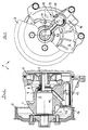
- a coolant pump 1 shown in FIGS. 1 and 2 for a not shown Liquid-cooled internal combustion engine, in particular as part of a drive unit of a vehicle, comprises a housing 2 with a recess 3 for receiving a bearing 4 of a shaft 5, on the one hand an impeller 6 for coolant delivery and on the other hand a drive pulley arranged outside the housing 2 7 carries.
- a housing 2 with a recess 3 for receiving a bearing 4 of a shaft 5, on the one hand an impeller 6 for coolant delivery and on the other hand a drive pulley arranged outside the housing 2 7 carries.
- a drive pulley arranged outside the housing 2 7 carries.
- a Mechanical seal 8 arranged on the impeller side has a collecting chamber 9 for a the mechanical seal 8 given coolant leakage provided by means of a Drain channel 10 discharged into a collection chamber 11 arranged in / on the housing 2 is in connection with the free environment via a ventilation duct 12 stands.
- the ventilation channel 12 into the collection chamber 11 in such a chamber section opens out when there is a change in speed the internal combustion engine serving as part of a movable drive unit is free of collected coolant.
- the connected to the chamber section of the collecting chamber 11, according to the invention Vent channel at least in sections to the direction of movement
- Internal combustion engine arranged essentially transversely upwards or upwards.
- FIGS. 1 and 2 A preferred arrangement of the collecting chamber 11 is shown in FIGS. 1 and 2 can be seen, an elongated in / on the housing 2 substantially parallel to the shaft 5 trained collection chamber 11 in the installed position of the coolant pump 1 the internal combustion engine, not shown, in a side region facing away from the machine of the housing 2 is arranged laterally below the shaft 5 in such a way that as a ventilation channel 12, an opening 13 in a above a leakage level 14 extending wall section 15 of the collecting chamber 11 is used.
- the collection chamber 11 has one one of the drive disk 7 facing, separate end limit 16 adjacent End area an extension 17 formed in the direction of the shaft 5, in which the outlet channel 10 of the collecting chamber 9 opens.
- This extension 17 serves as storage space for coolant displaced by a vehicle deceleration in the Collection chamber 11.
- This arrangement also creates the possibility of the opening 13 in the longitudinal center region of the collecting chamber 11 in the wall section 15 to arrange. With the opening that can be arranged halfway through the collecting chamber 11 13 is for both vehicle deceleration and vehicle acceleration a coolant ejection through the opening 13 avoided.
- the opening 13 is preferably for simple manufacture as a bore designed and of such a diameter that this bore 13th for optical control of the height of the leakage level 14 in the collection chamber 11 can serve.
- the opening 13 designed as a bore can also be used be of such a diameter that a float 18 of a float indicator 19 can be inserted into the collecting chamber 11 via the bore 13 and is connected to the buoyancy body 18 and penetrates the bore 13
- Display rod 20 with elastically protruding arms in the collecting chamber 11 21 is provided to secure the float display device 19th
- the indicator bar 20 is an inadmissible level of Leakage mirror 14 indicating marking equipped for an optical control.
- this marking can be done with an optical and / or an acoustic Remote display in operative connection.
Landscapes
- Engineering & Computer Science (AREA)
- Mechanical Engineering (AREA)
- General Engineering & Computer Science (AREA)
- Structures Of Non-Positive Displacement Pumps (AREA)
Applications Claiming Priority (2)
| Application Number | Priority Date | Filing Date | Title |
|---|---|---|---|
| DE10160876 | 2001-12-12 | ||
| DE10160876A DE10160876A1 (de) | 2001-12-12 | 2001-12-12 | Kühlmittelpumpe für eine flüssigkeitsgekühlte Brennkraftmaschine, insbesondere auf Fahrzeugen |
Publications (3)
| Publication Number | Publication Date |
|---|---|
| EP1319843A2 true EP1319843A2 (fr) | 2003-06-18 |
| EP1319843A3 EP1319843A3 (fr) | 2004-01-28 |
| EP1319843B1 EP1319843B1 (fr) | 2006-02-08 |
Family
ID=7708834
Family Applications (1)
| Application Number | Title | Priority Date | Filing Date |
|---|---|---|---|
| EP02024859A Expired - Lifetime EP1319843B1 (fr) | 2001-12-12 | 2002-11-08 | Pompe à liquide de refroidissement |
Country Status (2)
| Country | Link |
|---|---|
| EP (1) | EP1319843B1 (fr) |
| DE (2) | DE10160876A1 (fr) |
Cited By (1)
| Publication number | Priority date | Publication date | Assignee | Title |
|---|---|---|---|---|
| EP2048367A1 (fr) * | 2007-10-09 | 2009-04-15 | Siemens Aktiengesellschaft | Boîtier avec dispositif de refroidissement pour un turbocompresseur à gaz de processus |
Family Cites Families (9)
| Publication number | Priority date | Publication date | Assignee | Title |
|---|---|---|---|---|
| DE2846950C2 (de) * | 1978-10-27 | 1980-01-24 | Bayerische Motoren Werke Ag, 8000 Muenchen | Kühlmiftelpumpe für flüssigkeitsgekühlte Brennkraftmaschinen |
| JPH0623760Y2 (ja) * | 1988-09-27 | 1994-06-22 | アイシン精機株式会社 | ウォータポンプ |
| IT1237768B (it) * | 1989-11-15 | 1993-06-17 | Piaggio Adriatica Spa | Pompa di circolazione del liquido di raffreddamento per motori a combustione interna. |
| US5154576A (en) * | 1991-09-30 | 1992-10-13 | General Motors Corporation | Coolant pump drip collector with improved capacity |
| DE4318158A1 (de) * | 1992-08-10 | 1994-02-17 | Volkswagen Ag | Flüssigkeitspumpe, insbesondere Kühlmittelpumpe einer Brennkraftmaschine |
| US5226786A (en) * | 1992-08-14 | 1993-07-13 | General Motors Corporation | Coolant pump drip collector with splash control |
| US5490762A (en) * | 1995-03-21 | 1996-02-13 | Caterpillar Inc. | Weep hole plug for a fluid circulating pump |
| JPH0988592A (ja) * | 1995-09-29 | 1997-03-31 | Aisin Seiki Co Ltd | ウオータポンプ |
| AT409530B (de) * | 1999-04-29 | 2002-09-25 | Tcg Unitech Ag | Kühlwasserpumpe für eine brennkraftmaschine |
-
2001
- 2001-12-12 DE DE10160876A patent/DE10160876A1/de not_active Withdrawn
-
2002
- 2002-11-08 DE DE50205783T patent/DE50205783D1/de not_active Expired - Lifetime
- 2002-11-08 EP EP02024859A patent/EP1319843B1/fr not_active Expired - Lifetime
Cited By (1)
| Publication number | Priority date | Publication date | Assignee | Title |
|---|---|---|---|---|
| EP2048367A1 (fr) * | 2007-10-09 | 2009-04-15 | Siemens Aktiengesellschaft | Boîtier avec dispositif de refroidissement pour un turbocompresseur à gaz de processus |
Also Published As
| Publication number | Publication date |
|---|---|
| DE50205783D1 (de) | 2006-04-20 |
| EP1319843A3 (fr) | 2004-01-28 |
| DE10160876A1 (de) | 2003-06-26 |
| EP1319843B1 (fr) | 2006-02-08 |
Similar Documents
| Publication | Publication Date | Title |
|---|---|---|
| WO2004092639A2 (fr) | Dispositif et procede permettant de lubrifier et de refroidir des transmissions par engrenage | |
| DE102008022446A1 (de) | Ölsammelbehälter für eine Brennkraftmaschine | |
| DE2751982C2 (de) | Ölwanne für eine Mehrzylinder-Brennkraftmaschine | |
| EP1164281B1 (fr) | Dispositif pour pomper du carburant et pour ventiler le réservoir de carburant | |
| EP1319843A2 (fr) | Pompe à liquide de refroidissement | |
| EP2953826B1 (fr) | Dispositif déflecteur de vent destiné à un essuie-glace | |
| DE102008060409B4 (de) | Verbrennungsmotor | |
| EP0268970A1 (fr) | Compresseur encapsulé | |
| EP1637726B1 (fr) | Arrangement d'un boîtier de filtre à air pour pour un moteur à combustion interne dans le compartiment moteur d'un véhicule à moteur | |
| DE102005062573B4 (de) | Steuerventil | |
| WO2006136295A2 (fr) | Moteur a combustion interne a guidage de jauge d'huile integre | |
| DE102017207108B4 (de) | Spoilervorrichtung | |
| EP0936124A2 (fr) | Dispositif pour le centrage latéral actif et l'amortissement des vibrations de véhicules ferroviaires (AQZ cylindre) | |
| DE102019203367B4 (de) | Schutzrohrführungseinrichtung für einen Schwingungsdämpfer einer Kraftfahrzeugradaufhängung | |
| DE102004043936A1 (de) | Brennkraftmaschine mit einer Ölauffangvorrichtung | |
| EP1719657B1 (fr) | Unité d'alimentation arrangée dans un réservoir à carburant | |
| DE102019212550A1 (de) | Wischarmspoilervorrichtung mit zumindest einem Wischwasserkanal | |
| EP1179660B1 (fr) | Vase d'expansion pour un système de refroidissement d'un moteur à combustion interne, notamment pour véhicules | |
| DE102019008637A1 (de) | Außenspiegel für ein Kraftfahrzeug | |
| DE102012012796A1 (de) | Brennkraftmaschine für ein Kraftfahrzeug | |
| DE102022105977A1 (de) | Schmiermittelbehälter für eine Brennkraftmaschine sowie entsprechende Brennkraftmaschine | |
| DE102018126764B4 (de) | Luftansaugsystem für eine Luftfeder | |
| DE69400933T2 (de) | Flüssigkeitsdruckerhöhungsgerät in einem Tank, insbesondere zur Kraftstoffdruckerhöhung in einem Fahrzeugtank | |
| DE102009005749A1 (de) | Entlüftungselement für ein Gehäuse und Gehäuse | |
| EP1719658B1 (fr) | Unité d'alimentation arrangée dans un réservoir à carburant |
Legal Events
| Date | Code | Title | Description |
|---|---|---|---|
| PUAI | Public reference made under article 153(3) epc to a published international application that has entered the european phase |
Free format text: ORIGINAL CODE: 0009012 |
|
| AK | Designated contracting states |
Designated state(s): AT BE BG CH CY CZ DE DK EE ES FI FR GB GR IE IT LI LU MC NL PT SE SK TR |
|
| AX | Request for extension of the european patent |
Extension state: AL LT LV MK RO SI |
|
| PUAL | Search report despatched |
Free format text: ORIGINAL CODE: 0009013 |
|
| AK | Designated contracting states |
Kind code of ref document: A3 Designated state(s): AT BE BG CH CY CZ DE DK EE ES FI FR GB GR IE IT LI LU MC NL PT SE SK TR |
|
| AX | Request for extension of the european patent |
Extension state: AL LT LV MK RO SI |
|
| RIC1 | Information provided on ipc code assigned before grant |
Ipc: 7F 04D 29/12 B Ipc: 7F 04D 29/42 A Ipc: 7F 16J 15/00 B |
|
| 17P | Request for examination filed |
Effective date: 20040216 |
|
| AKX | Designation fees paid |
Designated state(s): DE FR GB IT |
|
| 17Q | First examination report despatched |
Effective date: 20050330 |
|
| GRAP | Despatch of communication of intention to grant a patent |
Free format text: ORIGINAL CODE: EPIDOSNIGR1 |
|
| GRAS | Grant fee paid |
Free format text: ORIGINAL CODE: EPIDOSNIGR3 |
|
| GRAA | (expected) grant |
Free format text: ORIGINAL CODE: 0009210 |
|
| AK | Designated contracting states |
Kind code of ref document: B1 Designated state(s): DE FR GB IT |
|
| PG25 | Lapsed in a contracting state [announced via postgrant information from national office to epo] |
Ref country code: IT Free format text: LAPSE BECAUSE OF FAILURE TO SUBMIT A TRANSLATION OF THE DESCRIPTION OR TO PAY THE FEE WITHIN THE PRESCRIBED TIME-LIMIT;WARNING: LAPSES OF ITALIAN PATENTS WITH EFFECTIVE DATE BEFORE 2007 MAY HAVE OCCURRED AT ANY TIME BEFORE 2007. THE CORRECT EFFECTIVE DATE MAY BE DIFFERENT FROM THE ONE RECORDED. Effective date: 20060208 |
|
| REG | Reference to a national code |
Ref country code: GB Ref legal event code: FG4D Free format text: NOT ENGLISH |
|
| GBT | Gb: translation of ep patent filed (gb section 77(6)(a)/1977) |
Effective date: 20060208 |
|
| REF | Corresponds to: |
Ref document number: 50205783 Country of ref document: DE Date of ref document: 20060420 Kind code of ref document: P |
|
| ET | Fr: translation filed | ||
| PLBE | No opposition filed within time limit |
Free format text: ORIGINAL CODE: 0009261 |
|
| STAA | Information on the status of an ep patent application or granted ep patent |
Free format text: STATUS: NO OPPOSITION FILED WITHIN TIME LIMIT |
|
| 26N | No opposition filed |
Effective date: 20061109 |
|
| REG | Reference to a national code |
Ref country code: FR Ref legal event code: PLFP Year of fee payment: 14 |
|
| REG | Reference to a national code |
Ref country code: FR Ref legal event code: PLFP Year of fee payment: 15 |
|
| REG | Reference to a national code |
Ref country code: FR Ref legal event code: PLFP Year of fee payment: 16 |
|
| PGFP | Annual fee paid to national office [announced via postgrant information from national office to epo] |
Ref country code: DE Payment date: 20211122 Year of fee payment: 20 Ref country code: FR Payment date: 20211119 Year of fee payment: 20 Ref country code: GB Payment date: 20211123 Year of fee payment: 20 |
|
| PGFP | Annual fee paid to national office [announced via postgrant information from national office to epo] |
Ref country code: IT Payment date: 20211130 Year of fee payment: 20 |
|
| REG | Reference to a national code |
Ref country code: DE Ref legal event code: R071 Ref document number: 50205783 Country of ref document: DE |
|
| REG | Reference to a national code |
Ref country code: GB Ref legal event code: PE20 Expiry date: 20221107 |
|
| PG25 | Lapsed in a contracting state [announced via postgrant information from national office to epo] |
Ref country code: GB Free format text: LAPSE BECAUSE OF EXPIRATION OF PROTECTION Effective date: 20221107 |
|
| P01 | Opt-out of the competence of the unified patent court (upc) registered |
Effective date: 20230502 |