EP1319946A2 - Vorrichtung und Verfahren zur Wirbelstromprüfung eines Prüflings mit einer planaren Oberfläche - Google Patents
Vorrichtung und Verfahren zur Wirbelstromprüfung eines Prüflings mit einer planaren Oberfläche Download PDFInfo
- Publication number
- EP1319946A2 EP1319946A2 EP02027448A EP02027448A EP1319946A2 EP 1319946 A2 EP1319946 A2 EP 1319946A2 EP 02027448 A EP02027448 A EP 02027448A EP 02027448 A EP02027448 A EP 02027448A EP 1319946 A2 EP1319946 A2 EP 1319946A2
- Authority
- EP
- European Patent Office
- Prior art keywords
- sensor
- assigned
- test specimen
- rotation angle
- eddy current
- Prior art date
- Legal status (The legal status is an assumption and is not a legal conclusion. Google has not performed a legal analysis and makes no representation as to the accuracy of the status listed.)
- Granted
Links
Images


Classifications
-
- G—PHYSICS
- G01—MEASURING; TESTING
- G01N—INVESTIGATING OR ANALYSING MATERIALS BY DETERMINING THEIR CHEMICAL OR PHYSICAL PROPERTIES
- G01N27/00—Investigating or analysing materials by the use of electric, electrochemical, or magnetic means
- G01N27/72—Investigating or analysing materials by the use of electric, electrochemical, or magnetic means by investigating magnetic variables
- G01N27/82—Investigating or analysing materials by the use of electric, electrochemical, or magnetic means by investigating magnetic variables for investigating the presence of flaws
- G01N27/90—Investigating or analysing materials by the use of electric, electrochemical, or magnetic means by investigating magnetic variables for investigating the presence of flaws using eddy currents
- G01N27/9013—Arrangements for scanning
- G01N27/902—Arrangements for scanning by moving the sensors
Definitions
- the present invention relates to an apparatus and a method for Eddy current testing of a linearly advanced test specimen with a planar surface.
- the eddy current test devices mentioned are not designed in the area of Measure the edges of the test specimen. If an eddy current sensor comes in from outside the device under test the area above the specimen surface can be moved due to the large Permeability jump on the edge of the test specimen no measurement in this area be made, which results in a certain system-related dead time, while which no sensible interpretable measurement data can be obtained. With yourself very fast moving eddy current sensor can lead to narrow specimens that a considerable part of the test specimen falls within the range of this dead time and therefore not can be measured.
- a material defect influencing the eddy currents can thus be understood as a change in impedance of the measuring coil coupled to the test object, where the error signal usually as a vector variable (amplitude and phase angle) in the Impedance level of the measuring coil is shown.
- the phase shift of the eddy currents regarding the excitation voltage depends among other things on the depth in the material.
- the excitation frequency determines the penetration depth and the phase shift of the eddy currents in one certain material depth.
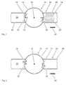
- FIG. 1 schematically shows the sensor area of a first embodiment of the invention shown.
- This is a so-called flat rotating probe 10, which is a comprises a stationary axis 12 rotating carrier disc 14 and an eddy current probe 16, which is fixedly mounted on the carrier disk 14 in the peripheral edge region thereof.
- the Direction of rotation of the disc 14 and thus the probe 16 is indicated by arrows 18 and 30.
- Below the carrier disc 14 is an electrically conductive test specimen 20 with a flat and comparatively narrow surface arranged in the direction of arrow 22 linear with im substantially constant speed (for example 40 to 60 m / min) moved forward becomes.
- the test specimen 20 can, for example, be one produced in a steel mill Trade billets, the flat sides of which are each an eddy current test using the Flat rotating probe 10 are subjected.
- the dimension of the test specimen 20 transverse to the Feed direction 22 is significantly smaller than the diameter of the carrier disk 14 or Orbital path of the probe 16, which is typically 250 mm, and is typically 60 up to 140 mm.
- the orbit diameter of the probe 16 should be chosen so that also in Edge area of the test specimen 20 the angle between the probe track and the longitudinal axis of the Test object 20 does not become too large, so that the probe is still sufficiently sensitive to 20 oriented errors is achieved in the longitudinal axis of the test specimen. With increasing angle between the probe and the longitudinal error the probe sensitivity decreases.
- a typical rotational speed of the carrier disk 14 is 3000 revolutions / min.
- the rotation speed should be high enough in relation to the feed speed, in order to ensure a sufficiently dense scanning in the longitudinal direction of the test specimen 20.
- the probe 16 can be, for example, an absolute coil or a differential coil act.
- the excitation coil is not shown in Fig. 1. In principle, however, the Excitation coil itself serve as a measuring coil.
- a distance probe 15 is preferably located in the vicinity of the eddy current probe 16 provided by means of which the distance between the probe 16 and the surface of the DUT 20 is monitored to the eddy current signal provided by the probe 16 to correct for fluctuations in distance or by an appropriate Distance control to prevent such fluctuations in distance.
- the two rotation angle ranges 18 and 30 are 180 ° offset and are chosen so that the probe is within these rotation angle ranges 18, 30 16 is located in the area of the test specimen surface 28, in which no influence of the shortly before swept edge 24 or 26 more occurs and in which the afterwards sweeping edge 26 or 24 does not yet affect the eddy current signal.
- the probe 16 becomes twice inside each other per revolution Arcs or sectors 18, 30 activated (the probe 16 is currently in the Area of the solid lines, while the dashed lines offset the 180 ° Rotational position of the probe 16 is indicated).
- the actual eddy current measurement is thus carried out essentially in the area of two complementary arcs 18 and 30 respectively resulting areas scanned by means of the probe 16 on the basis of eddy current signals of the surface 28 are in FIG. 1 as circular arcs designated by the reference symbols 18 'and 30' shown.
- a downstream computer determines the Associated geometric error position on the test specimen 20, which, for example, by an automatic color marking can be identified.
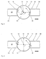
- FIG. 2 shows a modified embodiment in which two Eddy current sensors 16, 17 are provided instead of a single eddy current sensor 16, which are offset by 180 ° to one another in the circumferential direction of the disk 14.
- This one too Embodiment detects each probe 16, 17 during one revolution in two by 180 ° offset angular ranges or sectors measurement signals, due to the Symmetry of the arrangement, both probes 16, 17 are activated simultaneously.
- FIG. 3 shows a modified embodiment in which three sensors 16 in radial direction evenly distributed in the peripheral edge region of the carrier disk 14 are arranged.
- the sensors 16 are controlled so that they are in circulation only when passing through those indicated with arrows or dashed lines Sectors 18 and 30 are activated and deliver measured values to be evaluated, while for the Rest of the round are deactivated to exclude error signals.
- sensors 16 are provided. These also only deliver during the sweep Measured values to be evaluated in sectors 18 and 30.
- FIG. 5 shows the embodiment according to FIG. 2 with two probes or sensors 16 and 17 shown in somewhat more detail, the same for the same elements in FIGS. 2 and 5 Reference numerals are used.
- a spacer probe 15 and 19, respectively, are adjacent to the eddy current probes 16 and 17 arranged.
- the signals from the probes 15, 16, 17 and 19 are indicated schematically Signal lines 32 fed to a distance compensator 34, from where the signals one Signal evaluation unit with two channels 36 and 38 are supplied.
- a Encoder or position sensor 40 is provided which is adjacent to the Eddy current sensor 17 arranged mark 42 responds and its signal via a line 32 is also fed to the evaluation unit.
- the sectors 18 and 30, respectively, during which the two eddy current probes 16 and 17 respectively are activated, are selected so that they each extend from the center line 44 of the test object to Extend just in front of the edge 26 or 24, which means that the painting of each other edge 24 or 26 resulting signal interference in the area of sectors 18 and 30 should no longer occur.
- the activation of the eddy current probes 16 and 17 is based on that of the rotary encoder 40 received position signals controlled. 5 is thereby for example, the eddy current probe 16 is activated when the encoder mark 42 reaches the 90 ° or 270 ° position, due to the symmetrical 180 ° twisted arrangement of the probe 17 also applies to the probe 17.
- the signals of the distance probes 15 and 19 are also dependent on that of the angular position determined by the rotary encoder 40 is evaluated, i.e. these signals will sensibly evaluated only in the rotation angle ranges in which the Distance probes 15 and 19 are located above the specimen surface 28.
- the encoder signal is also used to determine the lateral position of a to determine the found defect of the test specimen 20, i.e. the evaluation of the signal of the Eddy current probes 16 and 17 are dependent on the angle of rotation, the eddy current signal is also shown on a display depending on the angle of rotation.
- the signal from the encoder 40 is also used to monitor or control the speed of the Carrier disc 14.
- FIGS. 6 to 11 show the structure and the mode of operation of the signal evaluation channels 36 and 38 are shown schematically. Accordingly, the signal evaluation channels 36 and 38 of two parallel signal processing stages ("frontends") 46 and 48, each of which is fixed Eddy current probes 16 and 17 are assigned two alarm processors arranged in parallel 50 and 52 and a two-channel display device 54 are formed.
- the alarm processors 50, 52 serve to recognize and locate signals which indicate an error of the Test object 20 indicate how it is indicated by way of example with the reference number 56.
- the Alarm processors 50 and 52 are respectively one of the two channels of the Display device 54 assigned.
- the assignment between the front ends 46 and 48 and In contrast, the alarm processors 50 and 52 is not fixed, but is in progress a rotation of the carrier disc 14 switched depending on the angle of rotation, as this is explained in more detail below.
- FIG. 6 shows a position in which the rotary encoder 40 and the rotary encoder mark 42 are congruent, with the eddy current probe 16 correspondingly located on the rotary encoder 40 is located.
- This position of the carrier disk 14 is defined as the 0 ° position, whereby in this position, the two probes 16 and 17 maximally far outside the specimen area 28 are located. In this position, both probes 16, 17 are deactivated and it is accordingly no signal is displayed on the display unit 54.
- the output of the front end 46 of the probe 16 is connected to the input of the alarm processor 50, while the output of the Front ends 48 of the probe 17 is connected to the input of the alarm processor 52. by virtue of the passage of the mark 42, the rotary encoder 40 is switched and gives a corresponding one Signal off.
- the carrier disc 14 has rotated 90 ° in the direction of the arrow, so that the probes 16 and 17 now come to rest in the center of the test specimen. Since both of them Probes 16 and 17 one of the measuring sectors or rotation angle ranges 18 and 30 reached have, both probes 16 and 17 are activated and the measurement signal recording for both Sectors 18 and 30 starts.
- the probes 16 and 17 are each approximately in the Middle of the sectors 18 and 30 and the respective so far covered and by the Alarm processors 50 and 52 issued and accordingly on the two channels of Display unit 54 displayed error signals are recorded. Since the probe 16 in the Area of error 56 is corresponding to that of alarm processor 50 associated upper channel of the display device 54 a corresponding error signal displayed while on the lower channel according to the absence of errors of the sector 30 no error signal appears.
- the probes 16 and 17 each reached the area of the edge 26 or 24 and are therefore already outside of measuring sectors 18 and 30 respectively. Probes 16 and 17 are deactivated accordingly.
- the outputs of the front ends 46 and 48 are cross-connected, i.e. the Front end 46 is now on the alarm processor 52 and the front end 48 on the Alarm processor 50 switched so that now the probe 16, the alarm processor 52 and the Probe 17 is assigned to the alarm processor 50.
- FIG. 10 shows a position in which the carrier disk 14 is in relation to the in Fig. 7 has rotated exactly 180 ° further, i.e. the probe 17 now has reaches the beginning of the measuring sector 18, while the probe 16 reaches the beginning of the measuring sector 30 has reached. Accordingly, the two probes 16 and 17 are reactivated to Record measurement signals.
- now Signal of the probe 16 fed to the alarm processor 52 while the signal of the probe 17th the alarm processor 50 is fed so that now the signal of the probe 16 on the lower Channel of the device 54 is shown, while the signal of the probe 17 is now on the upper channel is shown.
- FIG. 11 shows a position of the carrier disk 14 which is relative to that in FIG. 9 shown position is rotated by 180 °. Accordingly, the probe 17 just reaches the edge 26 and thus leaves the measuring sector 18, while the probe 16 reaches the edge 24 and so that the measuring sector 30 leaves. Probes 16 and 17 are deactivated accordingly.
- the upper channel of the display device 54 is now in addition to the error signal Probe 16 when passing through sector 18 according to FIGS. 8 and 9 now also the error signal of Probe 17 shown as it traverses sector 18.
- the in 11 shows the position between the front ends 46 and 48 and the Alarm processors 50 and 52 switched back to the configuration according to FIGS. 6 to 8, i.e. probe 16 is placed on alarm processor 50 and probe 17 on alarm processor 52 switched on, whereupon the cycle can start again.
- the two-channel configuration of the Signal processing unit (tandem mode) is useful if the number of Eddy current probes is even, since then the two measuring sectors 18 and 30 each of two eddy current probes are run through simultaneously (if the coils are evenly over the circumference of the carrier disk 14 are distributed, which is useful).
- the evaluation unit is generally designed so that the parameters relevant for the measurement, such as (angle) width of the measuring sectors, center offset of the sectors (definition of the position of the measuring sectors relative to the specimen cross direction), as well as angular offset of the sensors (displacement of the Sensors related to the encoder zero point) set by the operator for each application can be.
- the measuring sectors can also be chosen so that they over the Extend specimen center 44 and thus achieved a certain overlap of the probes becomes.
Landscapes
- Chemical & Material Sciences (AREA)
- Chemical Kinetics & Catalysis (AREA)
- Electrochemistry (AREA)
- Physics & Mathematics (AREA)
- Health & Medical Sciences (AREA)
- Life Sciences & Earth Sciences (AREA)
- Analytical Chemistry (AREA)
- Biochemistry (AREA)
- General Health & Medical Sciences (AREA)
- General Physics & Mathematics (AREA)
- Immunology (AREA)
- Pathology (AREA)
- Investigating Or Analyzing Materials By The Use Of Magnetic Means (AREA)
Abstract
Description
Claims (14)
- Vorrichtung zur Wirbelstromprüfung eines linear vorgeschobenen Prüflings (20) mit einer planaren Oberfläche (28), mit mindestens einem Sensor (16, 17) für in dem Prüfling induzierte Wirbelströme, einer von einem Antrieb zu einer Drehbewegung angetriebenen Trägeranordnung (14) für den mindestens einen Sensor, die so ausgebildet ist, dass jeder Sensor eine Kreisbahn beschreibt, die parallel zur Oberfläche des Prüflings liegt und deren Durchmesser größer als die Abmessung des Prüflings quer zur Vorschubrichtung ist, einem Drehgeber (40, 42) zur Erfassung des Drehwinkels des Sensors, sowie einer Signalauswertungseinheit (36, 38), die so ausgebildet ist, dass jedem Sensor zwei voneinander getrennte Drehwinkelbereiche (18, 30) zugeordnet werden, innerhalb welcher der betreffende Sensor den Prüfling überstreicht, und Signale des betreffenden Sensors jeweils nur innerhalb der beiden ihm zugeordneten Drehwinkelbereiche ausgewertet werden.
- Vorrichtung gemäß Anspruch 1, dadurch gekennzeichnet, dass die beiden einem jeden Sensor zugeordneten Drehwinkelbereiche (18, 30) um 180 Grad getrennt sind.
- Vorrichtung gemäß Anspruch 1 oder 2, dadurch gekennzeichnet, dass die Drehwinkelbereiche (18, 30) aller Sensoren (16, 17) identisch sind.
- Vorrichtung gemäß einem der vorhergehenden Ansprüche, dadurch gekennzeichnet, dass die Drehwinkelbereiche (18, 30) so ausgewählt sind, dass in den Drehwinkelbereichen keine durch den Randbereich (24, 26) des Prüflings (20) verursachte Störsignale auftreten.
- Vorrichtung gemäß einem der vorhergehenden Ansprüche, dadurch gekennzeichnet, dass die Sensoren (16, 17) in Umfangsrichtung gleichmäßig über die Kreisbahn verteilt sind.
- Vorrichtung gemäß einem der vorhergehenden Ansprüche, dadurch gekennzeichnet, dass eine gerade Anzahl von Sensoren (16, 17) vorgesehen ist und die Signalauswertungseinheit (50, 52, 54) zweikanalig ausgebildet ist, wobei jedem der beiden Drehwinkelbereiche einer der beiden Kanäle (50, 52) zugeordnet ist.
- Vorrichtung gemäß einem der Ansprüche 1 bis 5, dadurch gekennzeichnet, dass eine ungerade Anzahl von Sensoren (16) vorgesehen ist und die Signalauswertungseinheit einkanalig ausgebildet ist.
- Vorrichtung gemäß Anspruch 6, dadurch gekennzeichnet, dass jeder Kanal eine Fehlersignalerkennungseinheit (50, 52) aufweist.
- Vorrichtung gemäß Anspruch 8, dadurch gekennzeichnet, dass zwei Wirbelstromsensoren vorgesehen sind, wobei jedem Sensor eine eigene Signalbearbeitungseinheit zugeordnet ist, deren Ausgang je nach Drehwinkel der Sensoren so einer anderen der beiden Fehlersignalerkennungseinheiten (50, 52) zugeordnet ist, dass jedem der beiden Drehwinkelbereiche (18, 30) jeweils die gleiche der beiden Fehlersignalerkennungseinheiten (50, 52) zugeordnet ist.
- Vorrichtung gemäß einem der vorhergehenden Ansprüche, dadurch gekennzeichnet, dass jeder Sensor (16, 17) als Differenzspulenspaar ausgebildet ist.
- Vorrichtung gemäß einem der vorhergehenden Ansprüche, dadurch gekennzeichnet, dass mindestens eine Abstandssonde (15, 19) zur Erfassung des Abstands zwischen der Sensor-Kreisbahn und der Prüflingsoberfläche (28) an der Trägeranordnung (14) vorgesehen ist.
- Vorrichtung gemäß Anspruch 11, dadurch gekennzeichnet, dass für jeden Sensor (16, 17) in dessen Nähe eine Abstandssonde (15, 19) vorgesehen ist.
- Vorrichtung gemäß 11 oder 12, dadurch gekennzeichnet, dass eine Abstandsregelung (34) für die Trägeranordnung (14) vorgesehen ist, um anhand des Signals der Abstandssonde(n) (15, 19) den Abstand zwischen der Sensor-Kreisbahn und der Prüflingsoberfläche (28) konstant zu halten.
- Verfahren zur Wirbelstromprüfung eines linear vorgeschobenen Prüflings (20) mit einer planaren Oberfläche (28), wobei mindestens ein Sensor (16, 17) für in dem Prüfling induzierte Wirbelströme mittels einer von einem Antrieb zu einer Drehbewegung angetriebenen Trägeranordnung (14) auf einer Kreisbahn bewegt wird, die parallel zur Oberfläche des Prüflings liegt und deren Durchmesser größer als die Abmessung des Prüflings quer zur Vorschubrichtung ist, der Drehwinkels des Sensors erfasst wird, jedem Sensor zwei voneinander getrennte Drehwinkelbereiche zugeordnet werden, innerhalb welcher der betreffende Sensor den Prüfling überstreicht, und Signale des betreffenden Sensors jeweils nur innerhalb der beiden ihm zugeordneten Drehwinkelbereiche ausgewertet werden.
Applications Claiming Priority (2)
| Application Number | Priority Date | Filing Date | Title |
|---|---|---|---|
| DE10161973A DE10161973A1 (de) | 2001-12-17 | 2001-12-17 | Vorrichtung und Verfahren zur Wirbelstromprüfung eines Prüflings mit einer planaren Oberfläche |
| DE10161973 | 2001-12-17 |
Publications (3)
| Publication Number | Publication Date |
|---|---|
| EP1319946A2 true EP1319946A2 (de) | 2003-06-18 |
| EP1319946A3 EP1319946A3 (de) | 2004-08-04 |
| EP1319946B1 EP1319946B1 (de) | 2005-09-28 |
Family
ID=7709542
Family Applications (1)
| Application Number | Title | Priority Date | Filing Date |
|---|---|---|---|
| EP02027448A Revoked EP1319946B1 (de) | 2001-12-17 | 2002-12-10 | Vorrichtung und Verfahren zur Wirbelstromprüfung eines Prüflings mit einer planaren Oberfläche |
Country Status (3)
| Country | Link |
|---|---|
| EP (1) | EP1319946B1 (de) |
| AT (1) | ATE305609T1 (de) |
| DE (2) | DE10161973A1 (de) |
Cited By (2)
| Publication number | Priority date | Publication date | Assignee | Title |
|---|---|---|---|---|
| US20150276675A1 (en) * | 2014-03-28 | 2015-10-01 | Technical Software Consultants Limited | Alternating Current Field Measurement System |
| WO2019238303A1 (de) * | 2018-06-12 | 2019-12-19 | Bayerische Motoren Werke Aktiengesellschaft | Sensorvorrichtung und verfahren zum prüfen und/oder charakterisieren eines messobjekts |
Families Citing this family (4)
| Publication number | Priority date | Publication date | Assignee | Title |
|---|---|---|---|---|
| DE202012007180U1 (de) | 2012-07-25 | 2012-08-22 | Rohmann Gmbh | Vorrichtung zur Wirbelstromprüfung |
| DE102019206558B4 (de) * | 2019-05-07 | 2021-07-01 | Fertigungsgerätebau A. Steinbach GmbH & Co. KG | Prüfvorrichtung und Prüfverfahren zur zerstörungsfreien Bauteilprüfung sowie Herstellungsverfahren |
| DE102020105223B4 (de) | 2020-02-27 | 2021-11-04 | Gebrüder Linck, Maschinenfabrik "Gatterlinck" GmbH & Co. KG | Vorrichtung zur Vorhersage eines Blattabrisses eines Bandsägeblattes einer Bandsäge |
| DE102020216284A1 (de) | 2020-12-18 | 2022-06-23 | Fertigungsgerätebau Adolf Steinbach GmbH & Co. KG | Prüfvorrichtung, Prüfverfahren und Prüfprogramm zur zerstörungsfreien Bauteil- und/oder Werkstückprüfung und phasenabhängiger Kantenauswertung |
Family Cites Families (10)
| Publication number | Priority date | Publication date | Assignee | Title |
|---|---|---|---|---|
| US3611120A (en) * | 1970-02-24 | 1971-10-05 | Forster F M O | Eddy current testing systems with means to compensate for probe to workpiece spacing |
| GB2028510B (en) * | 1978-08-21 | 1983-02-16 | Defence Sercretary Of State Fo | Apparatus for the detection of defects in engineering materials |
| GB2068558B (en) * | 1980-01-29 | 1983-07-27 | British Steel Corp | Billet surface inspection system |
| DE3313820A1 (de) * | 1983-04-16 | 1984-10-18 | Institut Dr. Friedrich Förster Prüfgerätebau GmbH & Co KG, 7410 Reutlingen | Einrichtung zum pruefen der oberflaeche eines metallischen pruefteiles |
| SE456530B (sv) * | 1986-04-16 | 1988-10-10 | Tornbloms Kvalitetskontroll Ab | Anordning for provning och/eller metning av varma provobjekt |
| JP2681673B2 (ja) * | 1988-11-30 | 1997-11-26 | 原電子測器株式会社 | 平面探傷用交流漏洩磁束探傷装置 |
| US5043663A (en) * | 1989-10-19 | 1991-08-27 | Baker Hughes Incorporated | Method and apparatus for detecting angular defects in a tubular member |
| DE4003330A1 (de) * | 1990-02-05 | 1991-08-08 | Foerster Inst Dr Friedrich | Wirbelstrompruefgeraet |
| DE4021179A1 (de) * | 1990-07-03 | 1992-01-09 | Krautkraemer Gmbh | Verfahren zur band- und blechpruefung mittels ultraschall und vorrichtung zur durchfuehrung dieses verfahrens |
| DE9108161U1 (de) * | 1991-07-03 | 1991-09-05 | Rohmann, Jürgen, 6711 Beindersheim | Einrichtung zur Wirbelstrom-Werkstoffprüfung |
-
2001
- 2001-12-17 DE DE10161973A patent/DE10161973A1/de not_active Withdrawn
-
2002
- 2002-12-10 EP EP02027448A patent/EP1319946B1/de not_active Revoked
- 2002-12-10 DE DE50204387T patent/DE50204387D1/de not_active Expired - Lifetime
- 2002-12-10 AT AT02027448T patent/ATE305609T1/de not_active IP Right Cessation
Cited By (2)
| Publication number | Priority date | Publication date | Assignee | Title |
|---|---|---|---|---|
| US20150276675A1 (en) * | 2014-03-28 | 2015-10-01 | Technical Software Consultants Limited | Alternating Current Field Measurement System |
| WO2019238303A1 (de) * | 2018-06-12 | 2019-12-19 | Bayerische Motoren Werke Aktiengesellschaft | Sensorvorrichtung und verfahren zum prüfen und/oder charakterisieren eines messobjekts |
Also Published As
| Publication number | Publication date |
|---|---|
| ATE305609T1 (de) | 2005-10-15 |
| EP1319946B1 (de) | 2005-09-28 |
| DE10161973A1 (de) | 2003-06-26 |
| DE50204387D1 (de) | 2005-11-03 |
| EP1319946A3 (de) | 2004-08-04 |
Similar Documents
| Publication | Publication Date | Title |
|---|---|---|
| EP3161472B1 (de) | Verfahren und vorrichtung zur streuflussprüfung | |
| EP3581328B1 (de) | Werkzeugmaschineneinheit mit planlauffehler-kontrolle und prüfungsverfahren für den spannzustand | |
| DE2753635A1 (de) | Verfahren und vorrichtung zur automatischen ermittlung von rissen in schweisszonen, die in umfangsrichtung um ein rohr verlaufen | |
| DE10045715A1 (de) | Verfahren und Vorrichtung zur Prüfung eines Werkstücks mittels Wirbelströmen | |
| EP3889706B1 (de) | Verfahren zur prüfung des spannzustands während beschleunigungsphase | |
| DE102010009664B4 (de) | Vorrichtung zur Überwachung einer Arbeitsspindel | |
| DE3148609C2 (de) | ||
| EP1319946B1 (de) | Vorrichtung und Verfahren zur Wirbelstromprüfung eines Prüflings mit einer planaren Oberfläche | |
| EP1382411B1 (de) | Verfahren zum Vermessen des Intensitätsprofils eines Elektronenstrahls, insbesondere eines Strahls eines Elektronenstrahlbearbeitungsgeräts, und/oder zum Vermessen einer Optik für einen Elektronenstrahl und/oder zum Justieren einer Optik für einen elektronenstrahl, Messstruktur für ein solches Verfahren und Elektronenstrahlbearbeitungsgerät | |
| DE3525376C2 (de) | ||
| DE2914423A1 (de) | Verfahren zum unterscheiden gueltiger erster signale einer an einer zentrifuge befestigten probe und zentrifugenanordnung zur durchfuehrung dieses verfahrens | |
| EP3007857A2 (de) | Kalottenschleifgerät und verfahren zu dessen verwendung | |
| DE202021004532U1 (de) | Maschine zur Inspektion von Behältern | |
| DE3510973C2 (de) | ||
| EP1999464B1 (de) | Messverfahren und -system für bauteile, insbesondere für kolben von kolbenmaschinen | |
| DE102005010552B4 (de) | Vorrichtung und Verfahren zur Detektion von Fehlern auf bewegten Gegenständen | |
| DE202013103151U1 (de) | Vorrichtung zur zerstörungsfreien Wirbelstromprüfung eines Bauteils | |
| WO2005052568A1 (de) | Verfahren zur quantitativen längenbestimmung eines weichzonenbereiches eines teilgehärteten werkstückes | |
| CH706194A1 (de) | Messkopf zur Prüfung von Garn. | |
| EP3583414B1 (de) | Differenzsonde, prüfvorrichtung und herstellungsverfahren | |
| EP2216644A2 (de) | Verfahren und Vorrichtung zur Qualitätsprüfung | |
| DE4438171A1 (de) | Prüfvorrichtung und Verfahren zum Prüfen eines Prüfgegenstandes auf oberflächennahe Unregelmäßigkeiten | |
| DE69516302T2 (de) | Wirbelstromhybridsonde | |
| DE102020216284A1 (de) | Prüfvorrichtung, Prüfverfahren und Prüfprogramm zur zerstörungsfreien Bauteil- und/oder Werkstückprüfung und phasenabhängiger Kantenauswertung | |
| DE4421962C1 (de) | Verfahren und Vorrichtung zur optischen Vermessung von Mikroperforationsspuren in bewegtem Bahnmaterial |
Legal Events
| Date | Code | Title | Description |
|---|---|---|---|
| PUAI | Public reference made under article 153(3) epc to a published international application that has entered the european phase |
Free format text: ORIGINAL CODE: 0009012 |
|
| AK | Designated contracting states |
Designated state(s): AT BE BG CH CY CZ DE DK EE ES FI FR GB GR IE IT LI LU MC NL PT SE SI SK TR |
|
| AX | Request for extension of the european patent |
Extension state: AL LT LV MK RO SI |
|
| PUAL | Search report despatched |
Free format text: ORIGINAL CODE: 0009013 |
|
| AK | Designated contracting states |
Kind code of ref document: A3 Designated state(s): AT BE BG CH CY CZ DE DK EE ES FI FR GB GR IE IT LI LU MC NL PT SE SI SK TR |
|
| AX | Request for extension of the european patent |
Extension state: AL LT LV MK RO |
|
| 17P | Request for examination filed |
Effective date: 20041125 |
|
| GRAP | Despatch of communication of intention to grant a patent |
Free format text: ORIGINAL CODE: EPIDOSNIGR1 |
|
| AKX | Designation fees paid |
Designated state(s): AT BE BG CH CY CZ DE DK EE ES FI FR GB GR IE IT LI LU MC NL PT SE SI SK TR |
|
| GRAS | Grant fee paid |
Free format text: ORIGINAL CODE: EPIDOSNIGR3 |
|
| GRAA | (expected) grant |
Free format text: ORIGINAL CODE: 0009210 |
|
| AK | Designated contracting states |
Kind code of ref document: B1 Designated state(s): AT BE BG CH CY CZ DE DK EE ES FI FR GB GR IE IT LI LU MC NL PT SE SI SK TR |
|
| PG25 | Lapsed in a contracting state [announced via postgrant information from national office to epo] |
Ref country code: IT Free format text: LAPSE BECAUSE OF FAILURE TO SUBMIT A TRANSLATION OF THE DESCRIPTION OR TO PAY THE FEE WITHIN THE PRESCRIBED TIME-LIMIT;WARNING: LAPSES OF ITALIAN PATENTS WITH EFFECTIVE DATE BEFORE 2007 MAY HAVE OCCURRED AT ANY TIME BEFORE 2007. THE CORRECT EFFECTIVE DATE MAY BE DIFFERENT FROM THE ONE RECORDED. Effective date: 20050928 Ref country code: NL Free format text: LAPSE BECAUSE OF FAILURE TO SUBMIT A TRANSLATION OF THE DESCRIPTION OR TO PAY THE FEE WITHIN THE PRESCRIBED TIME-LIMIT Effective date: 20050928 Ref country code: SI Free format text: LAPSE BECAUSE OF FAILURE TO SUBMIT A TRANSLATION OF THE DESCRIPTION OR TO PAY THE FEE WITHIN THE PRESCRIBED TIME-LIMIT Effective date: 20050928 Ref country code: TR Free format text: LAPSE BECAUSE OF FAILURE TO SUBMIT A TRANSLATION OF THE DESCRIPTION OR TO PAY THE FEE WITHIN THE PRESCRIBED TIME-LIMIT Effective date: 20050928 Ref country code: EE Free format text: LAPSE BECAUSE OF FAILURE TO SUBMIT A TRANSLATION OF THE DESCRIPTION OR TO PAY THE FEE WITHIN THE PRESCRIBED TIME-LIMIT Effective date: 20050928 Ref country code: IE Free format text: LAPSE BECAUSE OF FAILURE TO SUBMIT A TRANSLATION OF THE DESCRIPTION OR TO PAY THE FEE WITHIN THE PRESCRIBED TIME-LIMIT Effective date: 20050928 Ref country code: SK Free format text: LAPSE BECAUSE OF FAILURE TO SUBMIT A TRANSLATION OF THE DESCRIPTION OR TO PAY THE FEE WITHIN THE PRESCRIBED TIME-LIMIT Effective date: 20050928 Ref country code: CZ Free format text: LAPSE BECAUSE OF FAILURE TO SUBMIT A TRANSLATION OF THE DESCRIPTION OR TO PAY THE FEE WITHIN THE PRESCRIBED TIME-LIMIT Effective date: 20050928 Ref country code: FI Free format text: LAPSE BECAUSE OF FAILURE TO SUBMIT A TRANSLATION OF THE DESCRIPTION OR TO PAY THE FEE WITHIN THE PRESCRIBED TIME-LIMIT Effective date: 20050928 |
|
| REG | Reference to a national code |
Ref country code: GB Ref legal event code: FG4D Free format text: NOT ENGLISH |
|
| REG | Reference to a national code |
Ref country code: CH Ref legal event code: EP |
|
| REG | Reference to a national code |
Ref country code: IE Ref legal event code: FG4D Free format text: LANGUAGE OF EP DOCUMENT: GERMAN |
|
| REF | Corresponds to: |
Ref document number: 50204387 Country of ref document: DE Date of ref document: 20051103 Kind code of ref document: P |
|
| PG25 | Lapsed in a contracting state [announced via postgrant information from national office to epo] |
Ref country code: CY Free format text: LAPSE BECAUSE OF FAILURE TO SUBMIT A TRANSLATION OF THE DESCRIPTION OR TO PAY THE FEE WITHIN THE PRESCRIBED TIME-LIMIT Effective date: 20051210 Ref country code: AT Free format text: LAPSE BECAUSE OF NON-PAYMENT OF DUE FEES Effective date: 20051210 |
|
| PG25 | Lapsed in a contracting state [announced via postgrant information from national office to epo] |
Ref country code: GR Free format text: LAPSE BECAUSE OF FAILURE TO SUBMIT A TRANSLATION OF THE DESCRIPTION OR TO PAY THE FEE WITHIN THE PRESCRIBED TIME-LIMIT Effective date: 20051228 Ref country code: SE Free format text: LAPSE BECAUSE OF FAILURE TO SUBMIT A TRANSLATION OF THE DESCRIPTION OR TO PAY THE FEE WITHIN THE PRESCRIBED TIME-LIMIT Effective date: 20051228 Ref country code: DK Free format text: LAPSE BECAUSE OF FAILURE TO SUBMIT A TRANSLATION OF THE DESCRIPTION OR TO PAY THE FEE WITHIN THE PRESCRIBED TIME-LIMIT Effective date: 20051228 Ref country code: BG Free format text: LAPSE BECAUSE OF FAILURE TO SUBMIT A TRANSLATION OF THE DESCRIPTION OR TO PAY THE FEE WITHIN THE PRESCRIBED TIME-LIMIT Effective date: 20051228 |
|
| PG25 | Lapsed in a contracting state [announced via postgrant information from national office to epo] |
Ref country code: BE Free format text: LAPSE BECAUSE OF NON-PAYMENT OF DUE FEES Effective date: 20051231 Ref country code: MC Free format text: LAPSE BECAUSE OF NON-PAYMENT OF DUE FEES Effective date: 20051231 Ref country code: LU Free format text: LAPSE BECAUSE OF NON-PAYMENT OF DUE FEES Effective date: 20051231 |
|
| PG25 | Lapsed in a contracting state [announced via postgrant information from national office to epo] |
Ref country code: ES Free format text: LAPSE BECAUSE OF FAILURE TO SUBMIT A TRANSLATION OF THE DESCRIPTION OR TO PAY THE FEE WITHIN THE PRESCRIBED TIME-LIMIT Effective date: 20060108 |
|
| GBT | Gb: translation of ep patent filed (gb section 77(6)(a)/1977) |
Effective date: 20060119 |
|
| PG25 | Lapsed in a contracting state [announced via postgrant information from national office to epo] |
Ref country code: PT Free format text: LAPSE BECAUSE OF FAILURE TO SUBMIT A TRANSLATION OF THE DESCRIPTION OR TO PAY THE FEE WITHIN THE PRESCRIBED TIME-LIMIT Effective date: 20060228 |
|
| NLV1 | Nl: lapsed or annulled due to failure to fulfill the requirements of art. 29p and 29m of the patents act | ||
| REG | Reference to a national code |
Ref country code: IE Ref legal event code: FD4D |
|
| ET | Fr: translation filed | ||
| PLBI | Opposition filed |
Free format text: ORIGINAL CODE: 0009260 |
|
| 26 | Opposition filed |
Opponent name: INSTITUT DR. FRIEDRICH FOERSTER PRUEFGERAETEBAU GM Effective date: 20060622 |
|
| PLAX | Notice of opposition and request to file observation + time limit sent |
Free format text: ORIGINAL CODE: EPIDOSNOBS2 |
|
| PLBB | Reply of patent proprietor to notice(s) of opposition received |
Free format text: ORIGINAL CODE: EPIDOSNOBS3 |
|
| PG25 | Lapsed in a contracting state [announced via postgrant information from national office to epo] |
Ref country code: CH Free format text: LAPSE BECAUSE OF NON-PAYMENT OF DUE FEES Effective date: 20061231 Ref country code: LI Free format text: LAPSE BECAUSE OF NON-PAYMENT OF DUE FEES Effective date: 20061231 |
|
| REG | Reference to a national code |
Ref country code: CH Ref legal event code: PL |
|
| BERE | Be: lapsed |
Owner name: PRUFTECHNIK DIETER BUSCH A.G. Effective date: 20051231 |
|
| PLAB | Opposition data, opponent's data or that of the opponent's representative modified |
Free format text: ORIGINAL CODE: 0009299OPPO |
|
| PLAY | Examination report in opposition despatched + time limit |
Free format text: ORIGINAL CODE: EPIDOSNORE2 |
|
| R26 | Opposition filed (corrected) |
Opponent name: INSTITUT DR. FRIEDRICH FOERSTER PRUEFGERAETEBAU GM Effective date: 20060622 |
|
| PLBC | Reply to examination report in opposition received |
Free format text: ORIGINAL CODE: EPIDOSNORE3 |
|
| PLAY | Examination report in opposition despatched + time limit |
Free format text: ORIGINAL CODE: EPIDOSNORE2 |
|
| PLAY | Examination report in opposition despatched + time limit |
Free format text: ORIGINAL CODE: EPIDOSNORE2 |
|
| PLBC | Reply to examination report in opposition received |
Free format text: ORIGINAL CODE: EPIDOSNORE3 |
|
| PGFP | Annual fee paid to national office [announced via postgrant information from national office to epo] |
Ref country code: GB Payment date: 20101221 Year of fee payment: 9 |
|
| PGFP | Annual fee paid to national office [announced via postgrant information from national office to epo] |
Ref country code: FR Payment date: 20120103 Year of fee payment: 10 |
|
| PLAB | Opposition data, opponent's data or that of the opponent's representative modified |
Free format text: ORIGINAL CODE: 0009299OPPO |
|
| R26 | Opposition filed (corrected) |
Opponent name: INSTITUT DR. FRIEDRICH FOERSTER PRUEFGERAETEBAU GM Effective date: 20060622 |
|
| PGFP | Annual fee paid to national office [announced via postgrant information from national office to epo] |
Ref country code: DE Payment date: 20120222 Year of fee payment: 10 |
|
| RDAF | Communication despatched that patent is revoked |
Free format text: ORIGINAL CODE: EPIDOSNREV1 |
|
| GBPC | Gb: european patent ceased through non-payment of renewal fee |
Effective date: 20121210 |
|
| REG | Reference to a national code |
Ref country code: FR Ref legal event code: ST Effective date: 20130830 |
|
| REG | Reference to a national code |
Ref country code: DE Ref legal event code: R119 Ref document number: 50204387 Country of ref document: DE Effective date: 20130702 |
|
| PG25 | Lapsed in a contracting state [announced via postgrant information from national office to epo] |
Ref country code: DE Free format text: LAPSE BECAUSE OF NON-PAYMENT OF DUE FEES Effective date: 20130702 |
|
| RDAG | Patent revoked |
Free format text: ORIGINAL CODE: 0009271 |
|
| STAA | Information on the status of an ep patent application or granted ep patent |
Free format text: STATUS: PATENT REVOKED |
|
| 27W | Patent revoked |
Effective date: 20120914 |
|
| REG | Reference to a national code |
Ref country code: AT Ref legal event code: MA03 Ref document number: 305609 Country of ref document: AT Kind code of ref document: T Effective date: 20120914 |