EP1320088A2 - Support-maítre d'informations pour transfert magnétique - Google Patents
Support-maítre d'informations pour transfert magnétique Download PDFInfo
- Publication number
- EP1320088A2 EP1320088A2 EP02028007A EP02028007A EP1320088A2 EP 1320088 A2 EP1320088 A2 EP 1320088A2 EP 02028007 A EP02028007 A EP 02028007A EP 02028007 A EP02028007 A EP 02028007A EP 1320088 A2 EP1320088 A2 EP 1320088A2
- Authority
- EP
- European Patent Office
- Prior art keywords
- magnetic
- master information
- magnetic layer
- information carrier
- base sheet
- Prior art date
- Legal status (The legal status is an assumption and is not a legal conclusion. Google has not performed a legal analysis and makes no representation as to the accuracy of the status listed.)
- Withdrawn
Links
- 230000005415 magnetization Effects 0.000 claims abstract description 33
- 239000000696 magnetic material Substances 0.000 claims abstract description 10
- 230000006872 improvement Effects 0.000 claims description 2
- 239000010410 layer Substances 0.000 description 94
- 230000004907 flux Effects 0.000 description 13
- 239000011159 matrix material Substances 0.000 description 13
- 238000000034 method Methods 0.000 description 11
- 230000000052 comparative effect Effects 0.000 description 10
- PXHVJJICTQNCMI-UHFFFAOYSA-N Nickel Chemical compound [Ni] PXHVJJICTQNCMI-UHFFFAOYSA-N 0.000 description 8
- 239000000969 carrier Substances 0.000 description 8
- 239000011521 glass Substances 0.000 description 7
- 239000000463 material Substances 0.000 description 6
- 239000002184 metal Substances 0.000 description 5
- 229910052751 metal Inorganic materials 0.000 description 5
- 238000004544 sputter deposition Methods 0.000 description 5
- 238000007747 plating Methods 0.000 description 4
- 238000011835 investigation Methods 0.000 description 3
- 230000001681 protective effect Effects 0.000 description 3
- XKRFYHLGVUSROY-UHFFFAOYSA-N Argon Chemical compound [Ar] XKRFYHLGVUSROY-UHFFFAOYSA-N 0.000 description 2
- 229910000684 Cobalt-chrome Inorganic materials 0.000 description 2
- 229910002546 FeCo Inorganic materials 0.000 description 2
- 229910002545 FeCoNi Inorganic materials 0.000 description 2
- 229910000990 Ni alloy Inorganic materials 0.000 description 2
- 229910045601 alloy Inorganic materials 0.000 description 2
- 239000000956 alloy Substances 0.000 description 2
- 239000010952 cobalt-chrome Substances 0.000 description 2
- 230000000694 effects Effects 0.000 description 2
- 238000005323 electroforming Methods 0.000 description 2
- 238000011156 evaluation Methods 0.000 description 2
- 238000007733 ion plating Methods 0.000 description 2
- 229910052742 iron Inorganic materials 0.000 description 2
- 239000000314 lubricant Substances 0.000 description 2
- 238000004519 manufacturing process Methods 0.000 description 2
- 229910052759 nickel Inorganic materials 0.000 description 2
- 239000002245 particle Substances 0.000 description 2
- 238000000206 photolithography Methods 0.000 description 2
- 239000011347 resin Substances 0.000 description 2
- 229920005989 resin Polymers 0.000 description 2
- 239000006188 syrup Substances 0.000 description 2
- 235000020357 syrup Nutrition 0.000 description 2
- 229910001149 41xx steel Inorganic materials 0.000 description 1
- OKTJSMMVPCPJKN-UHFFFAOYSA-N Carbon Chemical compound [C] OKTJSMMVPCPJKN-UHFFFAOYSA-N 0.000 description 1
- 229910000531 Co alloy Inorganic materials 0.000 description 1
- 229910019222 CoCrPt Inorganic materials 0.000 description 1
- 229910002441 CoNi Inorganic materials 0.000 description 1
- -1 CoPtCr Inorganic materials 0.000 description 1
- 229910052692 Dysprosium Inorganic materials 0.000 description 1
- 229910000640 Fe alloy Inorganic materials 0.000 description 1
- 229910002555 FeNi Inorganic materials 0.000 description 1
- 229910005335 FePt Inorganic materials 0.000 description 1
- 229910052779 Neodymium Inorganic materials 0.000 description 1
- 229910000943 NiAl Inorganic materials 0.000 description 1
- 229910001096 P alloy Inorganic materials 0.000 description 1
- NPXOKRUENSOPAO-UHFFFAOYSA-N Raney nickel Chemical compound [Al].[Ni] NPXOKRUENSOPAO-UHFFFAOYSA-N 0.000 description 1
- 229910052772 Samarium Inorganic materials 0.000 description 1
- 238000010521 absorption reaction Methods 0.000 description 1
- 229910000808 amorphous metal alloy Inorganic materials 0.000 description 1
- 229910052786 argon Inorganic materials 0.000 description 1
- 229910052799 carbon Inorganic materials 0.000 description 1
- 238000006243 chemical reaction Methods 0.000 description 1
- 235000008504 concentrate Nutrition 0.000 description 1
- 239000012141 concentrate Substances 0.000 description 1
- 239000013078 crystal Substances 0.000 description 1
- 230000006866 deterioration Effects 0.000 description 1
- 238000007772 electroless plating Methods 0.000 description 1
- 238000010894 electron beam technology Methods 0.000 description 1
- 238000005530 etching Methods 0.000 description 1
- 230000001747 exhibiting effect Effects 0.000 description 1
- 238000013213 extrapolation Methods 0.000 description 1
- 230000005307 ferromagnetism Effects 0.000 description 1
- 239000010419 fine particle Substances 0.000 description 1
- 229910052763 palladium Inorganic materials 0.000 description 1
- 230000035699 permeability Effects 0.000 description 1
- 238000003825 pressing Methods 0.000 description 1
- 230000008569 process Effects 0.000 description 1
- 239000011241 protective layer Substances 0.000 description 1
- 230000009467 reduction Effects 0.000 description 1
- 230000002787 reinforcement Effects 0.000 description 1
- 239000004065 semiconductor Substances 0.000 description 1
- 238000004528 spin coating Methods 0.000 description 1
- 238000001771 vacuum deposition Methods 0.000 description 1
Images


Classifications
-
- G—PHYSICS
- G11—INFORMATION STORAGE
- G11B—INFORMATION STORAGE BASED ON RELATIVE MOVEMENT BETWEEN RECORD CARRIER AND TRANSDUCER
- G11B5/00—Recording by magnetisation or demagnetisation of a record carrier; Reproducing by magnetic means; Record carriers therefor
- G11B5/86—Re-recording, i.e. transcribing information from one magnetisable record carrier on to one or more similar or dissimilar record carriers
-
- G—PHYSICS
- G11—INFORMATION STORAGE
- G11B—INFORMATION STORAGE BASED ON RELATIVE MOVEMENT BETWEEN RECORD CARRIER AND TRANSDUCER
- G11B5/00—Recording by magnetisation or demagnetisation of a record carrier; Reproducing by magnetic means; Record carriers therefor
- G11B5/86—Re-recording, i.e. transcribing information from one magnetisable record carrier on to one or more similar or dissimilar record carriers
- G11B5/865—Re-recording, i.e. transcribing information from one magnetisable record carrier on to one or more similar or dissimilar record carriers by contact "printing"
-
- B—PERFORMING OPERATIONS; TRANSPORTING
- B82—NANOTECHNOLOGY
- B82Y—SPECIFIC USES OR APPLICATIONS OF NANOSTRUCTURES; MEASUREMENT OR ANALYSIS OF NANOSTRUCTURES; MANUFACTURE OR TREATMENT OF NANOSTRUCTURES
- B82Y10/00—Nanotechnology for information processing, storage or transmission, e.g. quantum computing or single electron logic
-
- G—PHYSICS
- G11—INFORMATION STORAGE
- G11B—INFORMATION STORAGE BASED ON RELATIVE MOVEMENT BETWEEN RECORD CARRIER AND TRANSDUCER
- G11B5/00—Recording by magnetisation or demagnetisation of a record carrier; Reproducing by magnetic means; Record carriers therefor
- G11B5/74—Record carriers characterised by the form, e.g. sheet shaped to wrap around a drum
- G11B5/743—Patterned record carriers, wherein the magnetic recording layer is patterned into magnetic isolated data islands, e.g. discrete tracks
-
- G—PHYSICS
- G11—INFORMATION STORAGE
- G11B—INFORMATION STORAGE BASED ON RELATIVE MOVEMENT BETWEEN RECORD CARRIER AND TRANSDUCER
- G11B5/00—Recording by magnetisation or demagnetisation of a record carrier; Reproducing by magnetic means; Record carriers therefor
- G11B5/74—Record carriers characterised by the form, e.g. sheet shaped to wrap around a drum
- G11B5/82—Disk carriers
-
- Y—GENERAL TAGGING OF NEW TECHNOLOGICAL DEVELOPMENTS; GENERAL TAGGING OF CROSS-SECTIONAL TECHNOLOGIES SPANNING OVER SEVERAL SECTIONS OF THE IPC; TECHNICAL SUBJECTS COVERED BY FORMER USPC CROSS-REFERENCE ART COLLECTIONS [XRACs] AND DIGESTS
- Y10—TECHNICAL SUBJECTS COVERED BY FORMER USPC
- Y10T—TECHNICAL SUBJECTS COVERED BY FORMER US CLASSIFICATION
- Y10T428/00—Stock material or miscellaneous articles
- Y10T428/12—All metal or with adjacent metals
- Y10T428/12493—Composite; i.e., plural, adjacent, spatially distinct metal components [e.g., layers, joint, etc.]
- Y10T428/12986—Adjacent functionally defined components
-
- Y—GENERAL TAGGING OF NEW TECHNOLOGICAL DEVELOPMENTS; GENERAL TAGGING OF CROSS-SECTIONAL TECHNOLOGIES SPANNING OVER SEVERAL SECTIONS OF THE IPC; TECHNICAL SUBJECTS COVERED BY FORMER USPC CROSS-REFERENCE ART COLLECTIONS [XRACs] AND DIGESTS
- Y10—TECHNICAL SUBJECTS COVERED BY FORMER USPC
- Y10T—TECHNICAL SUBJECTS COVERED BY FORMER US CLASSIFICATION
- Y10T428/00—Stock material or miscellaneous articles
- Y10T428/24—Structurally defined web or sheet [e.g., overall dimension, etc.]
- Y10T428/24479—Structurally defined web or sheet [e.g., overall dimension, etc.] including variation in thickness
-
- Y—GENERAL TAGGING OF NEW TECHNOLOGICAL DEVELOPMENTS; GENERAL TAGGING OF CROSS-SECTIONAL TECHNOLOGIES SPANNING OVER SEVERAL SECTIONS OF THE IPC; TECHNICAL SUBJECTS COVERED BY FORMER USPC CROSS-REFERENCE ART COLLECTIONS [XRACs] AND DIGESTS
- Y10—TECHNICAL SUBJECTS COVERED BY FORMER USPC
- Y10T—TECHNICAL SUBJECTS COVERED BY FORMER US CLASSIFICATION
- Y10T428/00—Stock material or miscellaneous articles
- Y10T428/24—Structurally defined web or sheet [e.g., overall dimension, etc.]
- Y10T428/24942—Structurally defined web or sheet [e.g., overall dimension, etc.] including components having same physical characteristic in differing degree
- Y10T428/2495—Thickness [relative or absolute]
-
- Y—GENERAL TAGGING OF NEW TECHNOLOGICAL DEVELOPMENTS; GENERAL TAGGING OF CROSS-SECTIONAL TECHNOLOGIES SPANNING OVER SEVERAL SECTIONS OF THE IPC; TECHNICAL SUBJECTS COVERED BY FORMER USPC CROSS-REFERENCE ART COLLECTIONS [XRACs] AND DIGESTS
- Y10—TECHNICAL SUBJECTS COVERED BY FORMER USPC
- Y10T—TECHNICAL SUBJECTS COVERED BY FORMER US CLASSIFICATION
- Y10T428/00—Stock material or miscellaneous articles
- Y10T428/31—Surface property or characteristic of web, sheet or block
Definitions
- This invention relates to a master information carrier carrying thereon an irregularity pattern representing the information to be transferred to a magnetic medium.
- a magnetic recording medium which is high in memory capacity, low in cost and preferably requires a short time to read out a necessary part of data (a magnetic recording medium which allows so-called high-speed access).
- a magnetic recording medium which allows so-called high-speed access.
- a high recording density magnetic medium such as a hard disc or a ZIP (Iomega) in the form of a flexible disc.
- the recording area is formed by narrow data tracks.
- the so-called servo tracking technique has been employed.
- servo tracking In order to perform the servo tracking, it is necessary to write servo information such as servo tracking signals for positioning the data tracks, address signals for the data tracks and reproduction clock signals on the magnetic recording medium as a preformat upon production thereof.
- preformat recording is performed by the use of a specialized servo recording apparatus (a servo track writer) .
- a servo track writer a servo track writer
- the preformat recording by the conventional servo recording apparatus is disadvantageous in that it takes a long time since the servo information must be recorded on the magnetic recording medium one by one by the use of a magnetic head, which deteriorates the productivity.
- the magnetization pattern representing the information (e.g., servo information) carried by a master information carrier is magnetically transferred from the master information carrier to a slave medium by applying a transfer magnetic field to the slave medium and the master information in close contact with each other, and accordingly, the information carried by the master information carrier can be statically recorded on the slave medium with the relative position between the master information carrier and the slave medium kept constant.
- the preformat recording can be performed accurately and the time required for the preformat recording is very short.
- the master information carrier employed in the magnetic transfer disclosed in Japanese Unexamined Patent Publication No. 2001-14667 and U.S. Patent No. 6,347,016 comprises a patterned base sheet having on the surface thereof an irregularity pattern representing the information to be transferred and a magnetic layer formed at least on the surface of the protruding portions of the base sheet.
- the base sheet is non-magnetic
- the magnetic layer formed on the base sheet contributes to convergence of magnetic fluxes and convergence of magnetic fluxes concentrates on the magnetic layer
- turbulence is generated in the magnetic field established on the slave medium side, which deteriorates symmetry (increases the degree of asymmetry).
- the magnetic layer on the base sheet is as thin as several tens to several hundreds nm, and the edges of the protruding portions are sharp.
- the transfer magnetic layer Due to such a small thickness of the magnetic layer and such a shape of the magnetic layer, the transfer magnetic layer is stabilized in the energy state at the edges of the protruding portions and concentration of magnetic fluxes on the edges occurs, which, we have determined, causes uniformity of the magnetic field in the area of transfer to deteriorate.
- the primary object of the present invention is to provide an improved master information carrier for magnetic transfer which allows to obtain a high-quality signal from a slave medium.
- a master information carrier for magnetic transfer comprising a base sheet which is formed of a magnetic material and is provided with an irregularity pattern representing information to be transferred to an in-plane magnetic recording medium, and a magnetic layer formed along the irregularity pattern, wherein the improvement comprises that the saturation magnetization Ms of the base sheet and the saturation magnetization Mm of the magnetic layer satisfy the following condition, 1.0 ⁇ Mm/Ms ⁇ 100.
- the saturation magnetization Ms of the base sheet and the saturation magnetization Mm of the magnetic layer satisfy the following condition, 2.0 ⁇ Mm/Ms ⁇ 3.9.
- the magnetic material for the base sheet is a material which draws the magnetic fluxes into the base sheet when applied with a magnetic field and may comprise either elements of one kind or elements of a plurality of kinds. So long as the above condition is satisfied in total, the base sheet may contain non-magnetic elements.
- the magnetic layer be of a body-centered cubic structure (bcc) or a face-centered cubic structure (fcc) or an amorphous structure in crystallographic structure.
- the saturation magnetization Ms of the base sheet be not smaller than 5.65T (4500 Gauss).
- the height of the protruding portion of the irregularity pattern on the base sheet be not smaller than 40nm.
- the height h1 of the protruding portion of the irregularity pattern on the base sheet and the height h2 of the magnetic layer on the upper surface of the protruding portion of the irregularity pattern from the surface of magnetic layer on the recessed portion of the irregularity pattern i.e., the distance between the upper surface of the protruding portion of the irregularity pattern and the surface of magnetic layer on the recessed portion of the irregularity pattern
- the distance between the upper surface of the protruding portion of the irregularity pattern and the surface of magnetic layer on the recessed portion of the irregularity pattern satisfy the following formula 0.2 ⁇ h2/h1 ⁇ 0.8.
- the information to be transferred to the magnetic recording medium is, for instance, a servo signal.
- the transfer magnetic field in the slave medium can be rectified and the magnetization pattern representing the information carried by the master information carrier is optimally transferred from the master information carrier to a slave medium, whereby a high-quality reproduction signal can be obtained from the slave medium.
- the aforesaid effect obtained by forming the base sheet of a magnetic material and setting the saturation magnetization Ms of the base sheet and the saturation magnetization Mm of the magnetic layer to satisfy the aforesaid condition is remarkable in a master information carrier where the minimum inter-pattern distance (the minimum distance between the protruding portions) of the irregularity pattern is not larger than 300nm.
- the magnetic layer is of a body-centered cubic structure or a face-centered cubic structure or an amorphous structure in crystallographic structure.
- the magnetic layer is of Co.
- Co is normally of a hexagonal close-packed structure having an axis of easy magnetization in a direction of c-axis.
- it is necessary to apply a magnetic field in a circumferential direction when the slave medium is an in-plane recording medium and in a perpendicular direction when the slave medium is a perpendicular recording medium.
- the intensity of the transferred signal is weakened, which can result in reduction of output of the signal and/or a dull edge of the signal unless the axis of easy magnetization is controlled to be parallel to the direction of the transfer magnetic field.
- the axis of easy magnetization is controlled to be parallel to the direction of the transfer magnetic field.
- a material of a body-centered cubic structure or a face-centered cubic structure or an amorphous structure in crystallographic structure has no axis of easy magnetization
- all the magnetization is more apt to be orientated in the direction of the transfer magnetic field as compared with when the magnetic layer is formed of a hexagonal close-packed structure having an uncontrolled axis of easy magnetization. Since it is difficult to control the axis of easy magnetization, the manufacturing process can be simplified and the productive efficiency can be improved by using a magnetic material having no axis of easy magnetization.
- the ratio h2/h1 is smaller than 0.2, the distance by which the transfer magnetic field generated by magnetic fluxes released from edges of the protruding portions spreads in perpendicular to the surface of the magnetic layer is shortened and accordingly, magnetic fluxes cannot sufficiently penetrate into the slave medium as the distance between the master information carrier and the slave medium becomes large, whereas when the ratio h2/h1 is larger than 0.8, the transfer magnetic field leaks in the magnetic layer between the protruding portions of the irregularity pattern on the surface of the master information carrier, which results in fear that the transfer magnetic field can be insufficient in intensity.
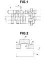
- a master information carrier 3 in accordance with the embodiment of the present invention is like a disc in shape and comprises a base sheet 3a having a plurality of protruding portions 31 arranged in a pattern formed on the surface thereof (as a result the base sheet 3a has an irregularity pattern) and a magnetic layer 3b formed along the irregularity pattern.
- the irregularity pattern represents information to be transferred to a magnetic recording media (slave media) and Figure 1 shows a part of the irregularity pattern.
- arrow X indicates the circumferential direction (the direction of track) and arrow Y indicates the radial direction.
- the information to be transferred may be a servo signal.
- Figure 2 is a fragmentary cross-sectional view of a part of the master information carrier 3 including a protruding portion 31 on the base sheet 3a taken along a line parallel to the direction X of track.
- the base sheet 3a and the magnetic layer3b are formed of materials such that the saturation magnetization Ms of the base sheet 3a and the saturation magnetization Mm of the magnetic layer 3b satisfy the condition 1.0 ⁇ Mm/Ms ⁇ 100 (preferably 2.0 ⁇ Mm/Ms ⁇ 3.9).
- the saturation magnetization Ms of the base sheet is not smaller than 5.65T (4500 Gauss).
- the base sheet 3a of the master information carrier 3 may be formed of nickel or nickel alloy.
- the magnetic layer 3b may be formed of ,for instance, alloys such as FeCo, FeCoNi and FeNi which contain at least one of Fe, Co, Ni, Gd, Dy, Sm, and Nd and are of a face-centered cubic structure (fcc) in crystallographic structure. So long as exhibiting ferromagnetism in total, the magnetic layer 3b may contain other magnetic elements or non-magnetic elements. Though may be soft, semi-hard or hard, it is preferred in view of obtaining better magnetic transfer that the magnetic layer 3b be a soft or semi-hard magnetic layer relatively small in coercive force.
- the magnetic layer 3b be of a body-centered cubic structure (bcc) or a face-centered cubic structure (fcc) or an amorphous structure in crystallographic structure.
- the magnetic layer 3b is of a body-centered cubic structure (bcc) or a face-centered cubic structure (fcc)
- the magnetic layer 3b has a particle structure where fine particles are arranged at random and each particle is not larger than 100nm in size as observed from the surface of the magnetic layer.
- the height h1 of the protruding portion 31 of the irregularity pattern on the base sheet 3a is not smaller than 40nm.
- the height h1 of the protruding portion of the irregularity pattern on the base sheet and the height h2 of the magnetic layer on the upper surface of the protruding portion of the irregularity pattern from the surface of magnetic layer on the recessed portion of the irregularity pattern satisfy the formula, 0.1 ⁇ h2/h1 ⁇ 0.8. More preferably, 0.3 ⁇ h2/h1 ⁇ 0.6.
- the magnetization pattern representing the information carried by the master information carrier is optimally transferred from the master information carrier to a slave medium 2, whereby a high-quality reproduction signal can be obtained from the slave medium 2.
- the height h1 of the protruding portion 31 of the irregularity pattern on the base sheet 3a is not smaller than 40nm and the height h1 of the protruding portion of the irregularity pattern on the base sheet and the height h2 of the magnetic layer on the upper surface of the protruding portion of the irregularity pattern from the surface of magnetic layer on the recessed portion of the irregularity pattern satisfy the formula, 0.2 ⁇ h2/h1 ⁇ 0.8, absorption and release of the magnetic fluxes at the edges of the protruding portions 31 can be improved and a higher-quality reproduction signal can be obtained from the slave medium 2.
- the base sheet 3a having thereon the irregularity pattern or the pattern of the protruding portions 31 can be formed, for instance, by the use of stamper method or photolithography.
- a photo-resist layer is first formed on a smooth glass plate (or a smooth crystal plate), for instance, by spin coating, and a laser beam (or an electron beam) modulated according to the servo signal is projected onto the photo-resist layer while rotating the glass plate so that the photo-resist layer is exposed to the laser beam in a predetermined pattern, e.g., a pattern of servo signals each extending in a radial direction in one track. Thereafter the photo-resist layer is developed and the part exposed to the laser beam is removed with an irregularity pattern of the photo-resist left on the glass plate, thereby obtaining a matrix.
- a laser beam or an electron beam modulated according to the servo signal
- Ni base sheet having a positive irregularity pattern is formed on the matrix and separated from the matrix.
- the Ni base sheet as it is may be used as a master information carrier or may be used as a master information carrier after forming a magnetic layer and a protective layer along the irregularity pattern as desired.
- the matrix may be plated to form a second matrix and the second matrix may be plated to form a base sheet having a negative irregularity pattern.
- a third matrix may be formed by plating the second matrix or pressing a resin syrup against the surface of the second matrix and curing the resin syrup, and a base sheet having a positive irregularity pattern may be formed by plating the third matrix.
- a matrix without photo-resist layer may be first formed by etching the glass plate with an irregularity pattern of the photo-resist to make holes in the glass plate, and a base sheet may be formed by the use of the matrix in the manner described above.
- the base sheet may be formed of metal such as Ni or Ni alloy as described above, and as the aforesaid plating for forming the metal base sheet, various metal film forming techniques such as electroless plating, electroforming, sputtering, or ion plating can be employed.
- the height of the protruding portion should be not smaller than 40nm, preferably in the range of 50 to 800nm and more preferably 80 to 600nm.
- each of the protruding portions is rectangle having longer sides in a radial direction of the base sheet and shorter sides in a circumferential direction of the same.
- each of the protruding portions is preferably 0.05 to 20 ⁇ m in the longer sides and 0.05 to 5 ⁇ m in the shorter sides.
- the magnetic layer 3b may be formed on the irregularity pattern by various vacuum film forming techniques or plating methods such as vacuum deposition, sputtering, ion plating and the like of magnetic material.
- the thickness of the magnetic layer 3b is preferably 50 to 500nm and more preferably 80 to 300nm.
- the ratio h2/h1 of the height h1 of the protruding portion of the irregularity pattern on the base sheet to the height h2 of the magnetic layer on the upper surface of the protruding portion of the irregularity pattern from the surface of magnetic layer on the recessed portion of the irregularity pattern is not smaller than 0.2 and not larger than 0.8.
- a protective film 5 to 30nm thick such as of DLC (diamond-like carbon) be provided on the magnetic layer on the upper surface of the protruding portion 31.
- a lubricant layer may be further provided on the protective film.
- a reinforcement layer such as a Si layer may be provided between the magnetic layer 3b and the protective film to enhance the contact therebetween. The lubricant layer suppresses deterioration in durability of the magnetic layer 3b, such as scores due to friction, which occurs in correcting for a shift generated when the magnetic layer 3b is brought into contact with the slave medium.
- a pair of master information carriers 3 and 4 are disposed on opposite sides of a slave medium 2.
- the slave medium 2 may be, for instance, a hard disc or a flexible disc.
- the slave medium 2 is provided with a pair of in-plane recording magnetic layers 2b and 2c formed on lower and upper sides of a disc-shaped base sheet 2a though the slave medium 2 may be provided with a single recording layer on one side thereof.
- Both the master information carriers 3 and 4 are in accordance with the present invention and respectively provided with irregularity patterns formed on the upper side of a base sheet 3a and the lower side of a base sheet 4a representing pieces of information to be transferred to the lower and upper magnetic layers 2b and 2c. Magnetic layers 3b and 4b are formed along the irregularity patterns.
- An initial DC magnetic field Hin is first applied to the slave medium 2 in one direction parallel to the recording tracks thereof, thereby magnetizing the magnetic layer 2b of the slave medium 2 in an initial DC magnetization as shown in Figure 4A. Thereafter, the magnetic layer 3b of the lower master information carrier 3 is brought into close contact with the lower magnetic layer 2b of the slave medium 2. In this state, a transfer magnetic field Hdu is applied in the direction opposite to the initial DC magnetic field Hin as shown in Figure 4B, thereby magnetically transferring the information on the master information carrier 3 to the lower magnetic layer 2b of the slave medium 2. As a result, information represented by the irregularity pattern on the master information carrier 3 is transferred to the lower magnetic layer 2b as shown in Figure 4C. The information represented by the irregularity patterns on a pair of master information carriers may be transferred to opposite sides of the slave medium either simultaneously or in sequence.
- the information can be magnetically transferred to the slave medium 2 by reversing the directions of the initial DC magnetic field Hin and the transfer magnetic field Hdu.
- the intensities of the initial DC magnetic field and the transfer magnetic field are determined on the basis of the coercive force of the slave medium 2, the specific permeabilities of the master information carrier and the slave medium, and the like.
- a magnetic recording disc such as a hard disc or a high-density flexible disc is generally employed as the slave medium 2.
- the magnetic layer thereof is generally of a coated magnetic material or a metal film.
- the material of the magnetic layer may be Co, Co alloy (e.g., CoPtCr, CoCr, CoPtCrTa, CoPtCrNbTa, CoCrB, CoNi, Co/Pd), Fe or Fe alloy (e.g., FeCo, FePt, FeCoNi).
- Co alloy e.g., CoPtCr, CoCr, CoPtCrTa, CoPtCrNbTa, CoCrB, CoNi, Co/Pd
- Fe or Fe alloy e.g., FeCo, FePt, FeCoNi
- the magnetic layer be higher in magnetic flux density and has a magnetic anisotropy conforming to the recording system of the slave medium, that is, in the case of an in-plane recording medium, in a direction parallel to the direction of tracks and in the case of a perpendicular recording medium, in a direction perpendicular to the direction of tracks.
- the magnetic layer of the slave medium is preferably not smaller than 10nm and not larger than 500nm in thickness, and more preferably not smaller than 20nm and not larger than 200nm in thickness.
- the magnetic layer of the slave medium 2 be provided with a non-magnetic primer layer on the base sheet side thereof in order to give the magnetic layer a necessary magnetic anisotropy.
- the primer layer may be, for instance, of Cr, CrTi, CoCr, CrTa, CrMo, NiAl, Ru or Pd, but should match to the magnetic layer in crystallographic structure and lattice constant.
- the thickness of the primer layer is preferably not smaller than 10nm and not larger than 150nm, and more preferably not smaller than 20nm and not larger than 80nm.
- the slave medium is an in-plane recording medium
- the present invention can be applied to the case where the slave medium is a perpendicular recording medium.
- the read signal was divided into frequencies by a spectro-analyzer, and the difference C/N between the peak intensity C of the primary signal and the medium noise N obtained by extrapolation was measured.
- the quality of the signal reproduced from the slave medium was evaluated on the basis of the relative values ⁇ C/N with the difference C/N between the peak intensity C of the primary signal and the medium noise N obtained from the same slave medium by recording and reproducing the same signal by the use of the same GMR head instead of magnetic transfer taken as 0 db.
- the transferred signal quality was evaluated as an excellent state ⁇
- the relative value ⁇ C/N is not smaller than -3.0 db and not smaller than -1.5 db
- the transferred signal quality was evaluated as a good state ⁇
- the relative value ⁇ C/N is smaller than -3.0 db
- the transferred signal quality was evaluated as a poor state ⁇ .
- the base sheet was formed of Ni by the use of stamper method.
- An irregularity pattern signal which were 1.0 ⁇ m in track width and 1.1 ⁇ m in track pitch and extended from an innermost position at a distance of 20mm from the center to an outermost position at a distance of 40mm from the center was formed on the base sheet in a height of 0.2 ⁇ m of the protruding portions.
- the bit length was 0.2 ⁇ m in the innermost position.
- a magnetic layer of FeCO (30at%) having a bcc structure was formed on the Ni base sheet at 25°C.
- the Ar sputtering pressure was 1.44 ⁇ 10 -1 Pa (1.08mTorr), and the power supplied was 2.80W/cm 2 .
- the master information carriers of the second to eighth embodiments and the first to third comparative examples were produced in manners similar to the first embodiment except that the base sheet and the magnetic layer were formed of different material and in different thickness so that the crystallographic structure of the magnetic layer, the value of Mm/Ms and the value of h2/h1 differ from those of the first embodiment.
- the master information carrier of the second embodiment was produced in the same manner as the first embodiment except that the magnetic layer was of Co having a hcp structure and Mm/Ms was 2.8.
- the master information carrier of the third embodiment was produced in the same manner as the first embodiment except that the magnetic layer was of CoNi50 having a fcc structure and Mm/Ms was 2.0.
- the master information carrier of the fourth embodiment was produced in the same manner as the first embodiment except that the magnetic layer was of FeMn50 having a bcc structure and Mm/Ms was 2.5.
- the master information carrier of the fifth embodiment was produced in the same manner as the first embodiment except that h2.h1 was 0.1.
- the master information carrier of the sixth embodiment was produced in the same manner as the first embodiment except that h2.h1 was 0.9.
- the master information carrier of the seventh embodiment was produced in the same manner as the first embodiment except that the base sheet was of (FeCO 2 )P alloy and Mm/Ms was 92.
- the master information carrier of the eighth embodiment was produced in the same manner as the first embodiment except that the magnetic layer was of Co FeB amorphous alloy and Mm/Ms was 2.0.
- the master information carrier of the first comparative example was produced in the same manner as the first embodiment except that the magnetic layer was of Ni having a fcc structure and Mm/Ms was 1.0.
- the master information carrier of the second comparative example was produced in the same manner as the first embodiment except that the magnetic layer was of CuNi80 having a fcc structure and Mm/Ms was 0.8.
- the master information carrier of the third comparative was produced in the same manner as the first embodiment except that the base sheet was of NiP alloy having a fcc structure and Mm/Ms was 113.
- the slave media were produced in the following manner. That is, 3.5" disc-shaped in-plane magnetic recording media were prepared by a sputtering apparatus (S-50S: Shibaura Mechatronics). The sputtering apparatus was evacuated to 1.33 ⁇ 10 -5 Pa (1.0 ⁇ 10 -4 Torr) at the room temperature and then argon was introduced into the apparatus to a pressure of 0.4Pa (3.0mTorr). Under these conditions, glass discs were heated to 200°C and a magnetic layer consisting of a 30nm thick CrTi and 30nm thick CoCrPt layer was formed on each of the glass discs.
- S-50S Shibaura Mechatronics
- the sputtering apparatus was evacuated to 1.33 ⁇ 10 -5 Pa (1.0 ⁇ 10 -4 Torr) at the room temperature and then argon was introduced into the apparatus to a pressure of 0.4Pa (3.0mTorr). Under these conditions, glass discs were heated to 200°C and
- Each of the slave media was 5.65T (4500 Gauss) in saturation magnetization Ms and 199kA/m (2500e) in coercive force.
- the embodiment which was a hcp structure in crystallographic structure as the second embodiment could not obtained ⁇ and could obtained only ⁇ in both the transferred signal quality and the asymmetry, which indicated that the magnetic layer which was a bcc, a fcc or an amorphous in crystallographic structure was better than that which was a hcp in crystallographic structure.
Landscapes
- Engineering & Computer Science (AREA)
- Chemical & Material Sciences (AREA)
- Nanotechnology (AREA)
- Physics & Mathematics (AREA)
- Mathematical Physics (AREA)
- Theoretical Computer Science (AREA)
- Crystallography & Structural Chemistry (AREA)
- Magnetic Record Carriers (AREA)
Applications Claiming Priority (2)
| Application Number | Priority Date | Filing Date | Title |
|---|---|---|---|
| JP2001380908 | 2001-12-14 | ||
| JP2001380908 | 2001-12-14 |
Publications (2)
| Publication Number | Publication Date |
|---|---|
| EP1320088A2 true EP1320088A2 (fr) | 2003-06-18 |
| EP1320088A3 EP1320088A3 (fr) | 2008-04-02 |
Family
ID=19187271
Family Applications (1)
| Application Number | Title | Priority Date | Filing Date |
|---|---|---|---|
| EP02028007A Withdrawn EP1320088A3 (fr) | 2001-12-14 | 2002-12-13 | Support-maître d'informations pour transfert magnétique |
Country Status (5)
| Country | Link |
|---|---|
| US (1) | US6911270B2 (fr) |
| EP (1) | EP1320088A3 (fr) |
| KR (1) | KR20030051281A (fr) |
| CN (1) | CN1234113C (fr) |
| SG (1) | SG110011A1 (fr) |
Cited By (1)
| Publication number | Priority date | Publication date | Assignee | Title |
|---|---|---|---|---|
| EP1347441A3 (fr) * | 2002-03-20 | 2003-11-19 | Fuji Photo Film Co., Ltd. | Original support d' enregistrement d' informations pour la transfer magnetique |
Families Citing this family (8)
| Publication number | Priority date | Publication date | Assignee | Title |
|---|---|---|---|---|
| JP3778428B2 (ja) * | 2001-09-06 | 2006-05-24 | 富士通株式会社 | 磁気パターン転写方法及び磁気パターン転写装置 |
| US7618721B1 (en) * | 2001-11-01 | 2009-11-17 | Seagate Technology Llc | Master for printing servo patterns |
| KR20030043747A (ko) * | 2001-11-28 | 2003-06-02 | 후지 샤신 필름 가부시기가이샤 | 자기전사용 마스터 담체 및 자기전사방법 |
| JP2007273061A (ja) * | 2006-03-31 | 2007-10-18 | Fujitsu Ltd | 磁気転写用マスタ及び垂直記録媒体の製造方法 |
| JP5695561B2 (ja) * | 2008-05-27 | 2015-04-08 | パーキンエルマー・ヘルス・サイエンシーズ・インコーポレイテッドPerkinelmer Health Sciences, Inc. | クロマトグラフィーシステムおよびそれを用いた方法 |
| AU2010228936B2 (en) * | 2009-03-24 | 2015-07-09 | Perkinelmer U.S. Llc | Sorbent devices with longitudinal diffusion paths and methods of using them |
| US8388736B2 (en) * | 2009-10-02 | 2013-03-05 | Perkinelmer Health Sciences, Inc. | Sorbent devices and methods of using them |
| AU2011267964B2 (en) | 2010-06-14 | 2015-07-09 | Perkinelmer U.S. Llc | Fluidic devices and methods of using them |
Citations (2)
| Publication number | Priority date | Publication date | Assignee | Title |
|---|---|---|---|---|
| EP0915456A1 (fr) | 1996-07-22 | 1999-05-12 | Matsushita Electric Industrial Co., Ltd | Support d'information maitre, procede de production dudit support et procede et appareil permettant d'enregistrer un signal d'information maitre sur un autre support d'enregistrement magnetique a l'aide du support maitre |
| EP1150280A2 (fr) | 2000-04-28 | 2001-10-31 | Fuji Photo Film Co., Ltd. | Méthode de transfert magnétique |
Family Cites Families (14)
| Publication number | Priority date | Publication date | Assignee | Title |
|---|---|---|---|---|
| FR2290730A1 (fr) * | 1974-11-08 | 1976-06-04 | Thomson Csf | Dispositif de memorisation d'information, utilisant des ondes elastiques |
| JPS63183623A (ja) | 1987-01-23 | 1988-07-29 | Sony Corp | 可撓性デイスクへの接触磁界転写方法 |
| JP3344651B2 (ja) * | 1998-10-29 | 2002-11-11 | 松下電器産業株式会社 | マスター情報担体を用いた磁気記録媒体の製造方法 |
| JP2001014667A (ja) | 1999-04-26 | 2001-01-19 | Fuji Photo Film Co Ltd | 磁気転写方法および磁気転写装置 |
| US6502757B1 (en) * | 1999-09-17 | 2003-01-07 | Dai Nippon Printing Co., Ltd. | Information recorded medium, device for reading the information, information recorded medium transfer foil, and method for producing information recorded medium |
| MY124923A (en) * | 2000-03-10 | 2006-07-31 | Fuji Photo Film Co Ltd | Master medium for magnetic transfer including metal disk with relief or recess pattern |
| JP2001325724A (ja) * | 2000-05-16 | 2001-11-22 | Fuji Photo Film Co Ltd | 磁気転写方法および磁気記録媒体 |
| JP2002050038A (ja) * | 2000-08-03 | 2002-02-15 | Fuji Photo Film Co Ltd | 磁気転写方法 |
| JP3963637B2 (ja) * | 2000-09-04 | 2007-08-22 | 富士フイルム株式会社 | 磁気転写方法 |
| US6906875B2 (en) * | 2001-05-15 | 2005-06-14 | Fuji Photo Film Co., Ltd. | Magnetic transfer device |
| KR20020088375A (ko) * | 2001-05-18 | 2002-11-27 | 후지 샤신 필름 가부시기가이샤 | 자기전사용 마스터담체 및 자기전사방법, 그리고자기전사용 마스터담체의 제작방법 |
| KR20030043747A (ko) * | 2001-11-28 | 2003-06-02 | 후지 샤신 필름 가부시기가이샤 | 자기전사용 마스터 담체 및 자기전사방법 |
| JP2003203325A (ja) * | 2001-12-28 | 2003-07-18 | Fujitsu Ltd | 磁気転写用マスタ媒体、磁気転写記録方法、磁気記録用スレーブ媒体および磁気転写用マスタ媒体の製造方法 |
| SG120091A1 (en) * | 2002-04-17 | 2006-03-28 | Fuji Electric Co Ltd | Perpendicular magnetic recording medium and the method of manufacturing the same |
-
2002
- 2002-12-12 US US10/317,111 patent/US6911270B2/en not_active Expired - Fee Related
- 2002-12-12 KR KR1020020079037A patent/KR20030051281A/ko not_active Withdrawn
- 2002-12-13 SG SG200207561A patent/SG110011A1/en unknown
- 2002-12-13 EP EP02028007A patent/EP1320088A3/fr not_active Withdrawn
- 2002-12-16 CN CNB021611025A patent/CN1234113C/zh not_active Expired - Fee Related
Patent Citations (2)
| Publication number | Priority date | Publication date | Assignee | Title |
|---|---|---|---|---|
| EP0915456A1 (fr) | 1996-07-22 | 1999-05-12 | Matsushita Electric Industrial Co., Ltd | Support d'information maitre, procede de production dudit support et procede et appareil permettant d'enregistrer un signal d'information maitre sur un autre support d'enregistrement magnetique a l'aide du support maitre |
| EP1150280A2 (fr) | 2000-04-28 | 2001-10-31 | Fuji Photo Film Co., Ltd. | Méthode de transfert magnétique |
Cited By (2)
| Publication number | Priority date | Publication date | Assignee | Title |
|---|---|---|---|---|
| EP1347441A3 (fr) * | 2002-03-20 | 2003-11-19 | Fuji Photo Film Co., Ltd. | Original support d' enregistrement d' informations pour la transfer magnetique |
| US6833969B2 (en) | 2002-03-20 | 2004-12-21 | Fuji Photo Film Co., Ltd. | Master information carrier for magnetic transfer |
Also Published As
| Publication number | Publication date |
|---|---|
| SG110011A1 (en) | 2005-04-28 |
| KR20030051281A (ko) | 2003-06-25 |
| US6911270B2 (en) | 2005-06-28 |
| CN1234113C (zh) | 2005-12-28 |
| US20030113583A1 (en) | 2003-06-19 |
| CN1441406A (zh) | 2003-09-10 |
| EP1320088A3 (fr) | 2008-04-02 |
Similar Documents
| Publication | Publication Date | Title |
|---|---|---|
| US7151641B2 (en) | Magnetic transfer master medium, magnetic transfer method, and magnetic transfer master medium forming method | |
| EP1316948A2 (fr) | Support d'information maítre pour transfert magnétique et méthode de transfert magnétique | |
| US6911270B2 (en) | Master information carrier for magnetic transfer | |
| EP1347441A2 (fr) | Original support d' enregistrement d' informations pour la transfer magnetique | |
| EP1398765B1 (fr) | Support-maítre d'informations pour transfert magnétique | |
| EP1511013A1 (fr) | Procédé de fabrication d'un milieu maítre pour transfert magnétique | |
| JP4046480B2 (ja) | 磁気転写方法および磁気転写装置 | |
| JP3986951B2 (ja) | 磁気転写用マスター担体および磁気転写方法 | |
| JP2003141715A (ja) | 磁気転写用マスター担体 | |
| US6777073B2 (en) | Magnetic recording medium | |
| EP1445765B1 (fr) | Support-maître d'informations pour transfert magnétique | |
| US7641822B2 (en) | Master information carrier for magnetic transfer and a method for producing the carrier | |
| JP2001028126A (ja) | 磁気転写方法および磁気転写装置 | |
| JP3964452B2 (ja) | 磁気転写用マスター担体 | |
| JP3999709B2 (ja) | 磁気転写用マスター担体および磁気転写方法 | |
| JP2003242629A (ja) | 磁気転写用マスター担体 | |
| EP1610303A1 (fr) | Procédé de fabrication d'un support d'enregistrement magnétique avec un rapport limité pour la rectangularité de la coercivité | |
| JP2001273632A (ja) | 磁気転写方法 | |
| JP2003296917A (ja) | 磁気記録媒体 | |
| US20090244746A1 (en) | Magnetic transfer method and magnetic recording medium | |
| US20100079894A1 (en) | Magnetic transfer master carrier and magnetic transfer method using the same | |
| JP2003173513A (ja) | 磁気転写用マスター担体および磁気転写用マスター担体の作製方法 | |
| JP2001014673A (ja) | 磁気転写方法および磁気転写装置 | |
| JP2003228817A (ja) | 磁気転写用マスター担体 | |
| JP2001014672A (ja) | 磁気転写方法および磁気転写装置 |
Legal Events
| Date | Code | Title | Description |
|---|---|---|---|
| PUAI | Public reference made under article 153(3) epc to a published international application that has entered the european phase |
Free format text: ORIGINAL CODE: 0009012 |
|
| AK | Designated contracting states |
Designated state(s): AT BE BG CH CY CZ DE DK EE ES FI FR GB GR IE IT LI LU MC NL PT SE SI SK TR |
|
| AX | Request for extension of the european patent |
Extension state: AL LT LV MK RO |
|
| RAP1 | Party data changed (applicant data changed or rights of an application transferred) |
Owner name: FUJIFILM CORPORATION |
|
| PUAL | Search report despatched |
Free format text: ORIGINAL CODE: 0009013 |
|
| AK | Designated contracting states |
Kind code of ref document: A3 Designated state(s): AT BE BG CH CY CZ DE DK EE ES FI FR GB GR IE IT LI LU MC NL PT SE SI SK TR |
|
| AX | Request for extension of the european patent |
Extension state: AL LT LV MK RO |
|
| 17P | Request for examination filed |
Effective date: 20080811 |
|
| AKX | Designation fees paid |
Designated state(s): DE FR GB |
|
| 17Q | First examination report despatched |
Effective date: 20091029 |
|
| STAA | Information on the status of an ep patent application or granted ep patent |
Free format text: STATUS: THE APPLICATION IS DEEMED TO BE WITHDRAWN |
|
| 18D | Application deemed to be withdrawn |
Effective date: 20130702 |