EP1320114A2 - Tastatur mit harter Bodemplatte - Google Patents
Tastatur mit harter Bodemplatte Download PDFInfo
- Publication number
- EP1320114A2 EP1320114A2 EP02017784A EP02017784A EP1320114A2 EP 1320114 A2 EP1320114 A2 EP 1320114A2 EP 02017784 A EP02017784 A EP 02017784A EP 02017784 A EP02017784 A EP 02017784A EP 1320114 A2 EP1320114 A2 EP 1320114A2
- Authority
- EP
- European Patent Office
- Prior art keywords
- key
- hole
- hard base
- key pad
- hard
- Prior art date
- Legal status (The legal status is an assumption and is not a legal conclusion. Google has not performed a legal analysis and makes no representation as to the accuracy of the status listed.)
- Withdrawn
Links
Images


Classifications
-
- H—ELECTRICITY
- H01—ELECTRIC ELEMENTS
- H01H—ELECTRIC SWITCHES; RELAYS; SELECTORS; EMERGENCY PROTECTIVE DEVICES
- H01H13/00—Switches having rectilinearly-movable operating part or parts adapted for pushing or pulling in one direction only, e.g. push-button switch
- H01H13/70—Switches having rectilinearly-movable operating part or parts adapted for pushing or pulling in one direction only, e.g. push-button switch having a plurality of operating members associated with different sets of contacts, e.g. keyboard
- H01H13/702—Switches having rectilinearly-movable operating part or parts adapted for pushing or pulling in one direction only, e.g. push-button switch having a plurality of operating members associated with different sets of contacts, e.g. keyboard with contacts carried by or formed from layers in a multilayer structure, e.g. membrane switches
-
- H—ELECTRICITY
- H01—ELECTRIC ELEMENTS
- H01H—ELECTRIC SWITCHES; RELAYS; SELECTORS; EMERGENCY PROTECTIVE DEVICES
- H01H2209/00—Layers
- H01H2209/006—Force isolators
-
- H—ELECTRICITY
- H01—ELECTRIC ELEMENTS
- H01H—ELECTRIC SWITCHES; RELAYS; SELECTORS; EMERGENCY PROTECTIVE DEVICES
- H01H2209/00—Layers
- H01H2209/01—Increasing rigidity; Anti-creep
-
- H—ELECTRICITY
- H01—ELECTRIC ELEMENTS
- H01H—ELECTRIC SWITCHES; RELAYS; SELECTORS; EMERGENCY PROTECTIVE DEVICES
- H01H2219/00—Legends
- H01H2219/054—Optical elements
- H01H2219/062—Light conductor
-
- H—ELECTRICITY
- H01—ELECTRIC ELEMENTS
- H01H—ELECTRIC SWITCHES; RELAYS; SELECTORS; EMERGENCY PROTECTIVE DEVICES
- H01H2221/00—Actuators
- H01H2221/06—Actuators to avoid sticking in on position
-
- H—ELECTRICITY
- H01—ELECTRIC ELEMENTS
- H01H—ELECTRIC SWITCHES; RELAYS; SELECTORS; EMERGENCY PROTECTIVE DEVICES
- H01H2229/00—Manufacturing
- H01H2229/044—Injection moulding
- H01H2229/048—Insertion moulding
Definitions
- the present invention relates to a key unit used for a mobile device such as a movable telephone and a personal digital assistance terminal (PDA), and more particularly to a key unit comprising a hard base made of a hard resin plate.
- a mobile device such as a movable telephone and a personal digital assistance terminal (PDA)
- PDA personal digital assistance terminal
- a key unit is one of the components constituting a mobile device such as a movable telephone and a PDA, and includes a number of switch operation keys (pushbutton) collectively arranged on one sheet surface.
- Each key includes a key top made of hard resin, which is firmly fixed to a surface of a key pad made of flexible rubber, and a switch thrusting projection (so-called "thruster") provided on its backside.
- the keys are connected to each other through the key pad.
- a key switch is formed at a position corresponding to each key.
- the conventional art has employed a structure, where the key top on the key unit is viewed from a key window provided on a casing surface of a movable telephone or the like.
- the foregoing problem may be attributed to the facts that the entire key unit is made of soft and elastic rubber, shape stability is lacking because of the excessively thin key unit, and the key top is slid in a cross direction because of deformation of the key unit during key pushing down.
- a soft key unit has a difficulty of being subjected to automatic assembling.
- a key unit similar to that shown in FIG. 8(A) which includes a ring-shaped projection (rib) provided around a center on the backside of the key top.
- a ring-shaped projection rib
- another problem that is, a shadow of the ring-shaped projection is seen from the key top upper surface, consequently spoiling the beauty.
- a first object of the present invention is to provide a key unit capable of improving its shape stability, preventing a key top from getting under a key window frame of a casing during key pushing down, preventing floating of the key top and interferences between keys on a narrow pitch keyboard which cannot employ a key window frame and can easily cope with an automatically assemble.
- a second object is to eliminate a dual structure, in which an light guiding plate as another component is superposed on a key unit.
- the first object can be achieved by combining a hard base made of a hard resin plate with a flexible key pad made of a rubber-like elastic body, and imparting rigidity to the entire key unit while making the best use of flexibility of the key pad locally.
- a translucent hard base is used, the second object can be simultaneously achieved because the hard base itself also serves as an light guiding plate.
- a first mode is that a required through hole (a key top is pushed down into this hole through the key pad) is provided on one flat hard base surface, and a rubber-like elastic body film as a key pad is formed in the through hole to close the through hole.
- a switch thrusting projection is formed on one side of the key pad simultaneously and integrally with the key pad, and a key top is provided at a position corresponding to the switch thrusting projection on its backside.
- the rubber film of the key pad is separated for each hole.
- Second and third modes of the combinations of the key pad and the hard base are similar to the first mode in that a rubber-like elastic body film as a key pad is formed to close a through hole in the hard base, and a key top and a switch thrusting projection are respectively provided on upper and lower surfaces of the key pad.
- the second mode is different from the first mode in that a rubber-like elastic body film connected to the key pad in the through hole is formed on an upper surface of a portion other than the through hole of the bard base (surface of the hard base directed in the same direction as that of the key pad, in which the key top is present. Its backside is called an "undersurface".).
- the third mode is different from the first mode in that rubber-like elastic films connected to the key pad are formed on both upper and lower surfaces of a portion other than the through hole of the hard base.
- the rubber-like elastic body film of the key pad is continuous over each hole, and joined to the hard base on other than the hole.
- the second object can be achieved by imparting translucency to the hard base, the key pad and the key top in the foregoing mode of the key pad and the hard base.
- a hole for inserting the light emitting device may be provided on a portion other than the through hole of the hard base.
- FIGS. 1 to 3 correspond to the foregoing first to third modes in the combinations of the key pad and the hard base.
- reference numeral 1 denotes a through hole; 2, a hole for inserting a light emitting device; 10, a hard base; 11, a key pad; 12, a switch thrusting projection; 13, a rubber film formed on an upper surface (key top side) of the hard base; 14, a rubber film formed on an undersurface (switch thrusting projection side) of the hard base and 15, a key top.
- a printed-circuit board including switch elements and a light emitting device are shown to assist understanding, but these components are outside a scope of the present invention.
- the hard base key unit includes a hard base 10 made of a hard resin plate and having a through hole 1 on a plane thereof, a key pad 11 made of a rubber elastic body film to cover the through hole 1 of the hard base 10, a switch thrusting projection 12 formed integrally with the key pad 11 on a surface of the key pad 11 facing the inside of the through hole 1, and a key top 15 made of a hard resin plate and provided at a position corresponding to the switch thrusting projection 12 on the other surface of the key pad 11.
- the key pad 11 is present only in the through hole 1 of the hard base 10 (end surface of the key pad 11 is joined to a side wall of the through hole 1), and not superposed on a surface of the hard base 10. Accordingly, if a thickness from a key top upper surface to a key unit lower surface is constant, a thickest (highest rigidity) hard base 10 can be employed compared with other modes.
- a hard base key unit includes a hard base 10 made of a hard resin plate and having a through hole 1 on a plane thereof, a key pad 11 made of a rubber-like elastic body film to cover the through hole 1 of the hard base 10, a rubber-like elastic body film 13 are molded integrally to the key pad 11 on a surface of a portion other than the through hole 1 of the hard base 10, a switch thrusting projection 12 formed integrally with the key pad 11 on a surface of the key pad 11 facing the inside of the through hole 1, and a key top 15 made of a hard resin plate and provided at a position corresponding to the switch thrusting projection 12 on the other surface of the key pad 11.
- a hard base key unit includes a hard base 10 made of a hard resin plate and having a through hole 1 on a plane thereof, a key pad 11 made of a rubber-like elastic body film to cover the through hole 1 of the hard base 10, a rubber-like elastic body film 13 are molded integrally to the key pad 11 on an upper surface of a portion other than the through hole 1 of the hard base 10, a rubber-like elastic body film 14 are molded integrally to the key pad 11 on an undersurface of a portion other than the through hole 1 of the hard base 10, a switch thrusting projection 12 formed integrally with the key pad 11 on a surface of the key pad 11 facing the inside of the through hole 1, and a key top 15 made of hard resin and provided at a position corresponding to the switch thrusting projection 12 on the other surface of the key pad 11.
- the key pad 11 is joined to the hard base 10 on both upper and lower surfaces of the hard base 10 in addition to a side wall of the through hole 1, a joining area between the two can be set largest compared with the first and second modes, thereby achieving a most robust joining state.
- FIGS. 1 to 3 That is, in a hard base key unit, a hard base 10, a key pad 11 and a key top 15 have translucency, and a hole 2 for inserting a light emitting device is formed on a portion other than the through hole 1 of the hard base 10.
- the translucent hard base used in this mode also serves as an light guiding plate. Accordingly, it is not necessary to superpose an light guiding plate as another body on the key unit, and thus the entire device can be made thin.
- a fifth mode of the present invention relates to a method for manufacturing the hard base key unit of the fourth mode. That is, the hard base key unit manufacturing method includes a step of forming a key top 15 by using translucent hard resin, a step of making a plate-like hard base 10 made of translucent hard resin, the hard base 10 having a through hole 1 and a hole 2 for inserting a light emitting device on a plane thereof, a step of arranging the hard base 10 in a molding die, a step of poring a translucent rubber elastic body material in the molding die, and forming a key pad 11 made of a film of the rubber elastic body integrally with the hard base 10, a step of forming a switch thrusting projection 12 integrally with the key pad 11 on a surface of the key pad 11 facing the inside of the though through hole 1, and a step of providing the key top 15 in a position corresponding to the switch thrusting projection 12 on a surface opposite the switch thrusting projection 12 so as to sandwich the key pad 11 therebetween.
- a so-called insertion molding method in which a hard base 10 as a separate body is formed beforehand, the hard base 10 is arranged in a molding die, and poring a translucent rubber-like elastic body material is poured into the molding die.
- a proper pretreatment is carried out for activating a surface of the hard base 10 beforehand in order to firmly join together the hard base 10 made of hard resin and the key pad 11 made of a rubber-like elastic body.
- FIG. 4 is a plan view showing a hard base 10 in a hard base unit according to this embodiment.
- the hard base 10 shown in FIG. 4 includes through holes 1 of various shapes, holes 2 for inserting light emitting devices, and two positioning holes provided on an upper side.
- the through holes 1 shown in FIG. 4 have five different shapes.
- the uppermost through hole corresponds to one multi-direction operative key.
- Short square through holes in both sides of a second stage have three sides, and each corresponds to one key.
- An oblong through hole in a center of the second stage corresponds to two keys.
- six elliptical through holes each corresponding to one key are arrayed.
- a large through hole at the lowest stage includes six keys.
- FIG. 5 is a plan view showing a state where a key pad 11 is formed to close each through hole 1.
- a hatched portion by dotted lines indicates a key pad 11.
- a small circle on a plane of the key pad 11 represents a switch thrusting projection 12 formed on a backside of the key pad 11.
- FIG. 6(A) is a plan view showing a state where a key top 15 is placed on a surface of the key pad 11 shown in FIG. 5, and a key unit is completed.
- FIG. 6(B) is a sectional view taken on cutting line A-A of FIG. 6(A).
- FIG. 6(C) is a sectional view taken on cutting line B-B of FIG. 6(A).
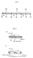
- a side sectional view where a key pad 11, a switch thrusting projection 12 and a key top 15 are assembled in each through hole 1 is shown in FIG. 1.
- the key pad 11 is formed for each through hole in such a way as to close the through hole 1 on the plane of the hard base 10 made of one hard resin plate, and the key tops 15 and the switch thrusting projections 12 are respectively placed by required set numbers on the surface and backside of the hard base 10.
- the key pads are dispersedly arranged for every through holes 1 different from the conventional case where the entire key pad is arranged as one continuous sheet.
- a light emitting device can be arranged on the center of thickness of the translucent hard base 10. Since light emitted from the light emitting device is transmitted through the hard base 10 and further transmitted through the through hole 1 into the key pad 11 made of the translucent rubber, the light from the light emitting device is surely guided to the backside of the key top 15. Since the hard base 10 apparently serves as the light guiding plate, it is not necessary to superpose an light guiding plate as a separate component, thereby achieving thinning of the device.
- FIG. 7 is a side sectional view showing the narrow pitch key unit according to the second embodiment.
- reference numerals similar to those of the first embodiment are used.
- a diameter of the through hole 1 on the hard base 10 is set slightly larger than that of the key top 15. Conversely, the one in the present embodiment is set smaller, and an arrangement is made such that a boundary portion (bridge portion) between through holes can correspond to a narrow space between adjacent key tops 15.
- the hard base serves as the conventional light guiding plate, and it is not necessary to superpose an light guiding plate as a separate component on the key unit, the device can be made thin.
Landscapes
- Push-Button Switches (AREA)
- Telephone Set Structure (AREA)
Applications Claiming Priority (2)
| Application Number | Priority Date | Filing Date | Title |
|---|---|---|---|
| JP2001378152A JP2003178639A (ja) | 2001-12-12 | 2001-12-12 | ハードベース・キーユニット |
| JP2001378152 | 2001-12-12 |
Publications (2)
| Publication Number | Publication Date |
|---|---|
| EP1320114A2 true EP1320114A2 (de) | 2003-06-18 |
| EP1320114A3 EP1320114A3 (de) | 2005-02-09 |
Family
ID=19185956
Family Applications (1)
| Application Number | Title | Priority Date | Filing Date |
|---|---|---|---|
| EP02017784A Withdrawn EP1320114A3 (de) | 2001-12-12 | 2002-08-12 | Tastatur mit harter Bodemplatte |
Country Status (5)
| Country | Link |
|---|---|
| US (1) | US7250937B2 (de) |
| EP (1) | EP1320114A3 (de) |
| JP (1) | JP2003178639A (de) |
| CN (1) | CN100489742C (de) |
| DE (1) | DE02017784T1 (de) |
Cited By (5)
| Publication number | Priority date | Publication date | Assignee | Title |
|---|---|---|---|---|
| EP1619703A3 (de) * | 2004-07-20 | 2006-11-29 | Polymatech Co., Ltd. | Folientastatur und Herstellungsmethode |
| GB2412244B (en) * | 2004-02-20 | 2007-06-06 | Pelikon Ltd | Switches |
| EP1876621A1 (de) * | 2006-07-03 | 2008-01-09 | Polymatech Co., Ltd. | Tastenfolie und Drucktastenschalter |
| EP1737010A4 (de) * | 2004-03-25 | 2009-04-15 | Shinetsu Polymer Co | Abdeckglied für einen druckschalter und herstellungsverfahren dafür |
| EP1758139A4 (de) * | 2004-04-05 | 2010-01-13 | Sunarrow Ltd | Schlüsseleinheit mit verstärkungsplatte |
Families Citing this family (31)
| Publication number | Priority date | Publication date | Assignee | Title |
|---|---|---|---|---|
| JP4473538B2 (ja) * | 2003-04-11 | 2010-06-02 | ポリマテック株式会社 | キーシート |
| US7262379B2 (en) * | 2003-04-11 | 2007-08-28 | Polymatech Co., Ltd. | Key sheets and method of producing the same |
| JP4194887B2 (ja) * | 2003-06-10 | 2008-12-10 | 信越ポリマー株式会社 | 押釦構造体及び押釦構造体の製造方法 |
| JP4625292B2 (ja) * | 2003-09-03 | 2011-02-02 | ポリマテック株式会社 | キーシート及びキーシートの製造方法 |
| JP4398738B2 (ja) * | 2004-01-09 | 2010-01-13 | ポリマテック株式会社 | キーシート |
| JP4305212B2 (ja) * | 2004-02-18 | 2009-07-29 | 日本電気株式会社 | 携帯電話機及びその製造方法 |
| KR100878171B1 (ko) * | 2004-03-25 | 2009-02-20 | 신에츠 폴리머 가부시키가이샤 | 누름 버튼 스위치용 커버 부재와 그 제조 방법 |
| EP1746616A4 (de) | 2004-05-07 | 2010-01-13 | Sunarrow Ltd | Schlüsseleinheit mit trägerrahmen |
| EP1768146A4 (de) * | 2004-05-28 | 2010-01-13 | Sunarrow Ltd | Schlüsseleinheit mit gehäuse |
| JP4679226B2 (ja) * | 2004-10-28 | 2011-04-27 | ポリマテック株式会社 | 押釦スイッチ用カバーシート |
| US7525534B2 (en) * | 2005-03-14 | 2009-04-28 | Palm, Inc. | Small form-factor keypad for mobile computing devices |
| US9142369B2 (en) | 2005-03-14 | 2015-09-22 | Qualcomm Incorporated | Stack assembly for implementing keypads on mobile computing devices |
| CN100463088C (zh) * | 2005-04-26 | 2009-02-18 | 乐金电子(昆山)电脑有限公司 | 按钮组件及其制造方法 |
| CN100452267C (zh) * | 2005-04-26 | 2009-01-14 | 佛山市顺德区顺达电脑厂有限公司 | 按键组 |
| KR100692742B1 (ko) | 2005-05-13 | 2007-03-09 | 삼성전자주식회사 | 도광층을 갖는 키 패드 및 키 패드 어셈블리 |
| ATE418149T1 (de) | 2005-05-19 | 2009-01-15 | Samsung Electronics Co Ltd | Tastatur und tastaturanordnung |
| KR100689392B1 (ko) | 2005-05-19 | 2007-03-02 | 삼성전자주식회사 | 키 패드와 그를 이용한 키 패드 어셈블리 |
| US7394030B2 (en) | 2005-06-02 | 2008-07-01 | Palm, Inc. | Small form-factor keyboard using keys with offset peaks and pitch variations |
| JP4394047B2 (ja) * | 2005-08-05 | 2010-01-06 | 信越ポリマー株式会社 | キーフレームおよび押釦スイッチ用カバー部材 |
| JP4698336B2 (ja) * | 2005-08-29 | 2011-06-08 | ポリマテック株式会社 | キートップ付キーシート |
| US8989822B2 (en) | 2006-09-08 | 2015-03-24 | Qualcomm Incorporated | Keypad assembly for use on a contoured surface of a mobile computing device |
| KR101228452B1 (ko) * | 2006-09-12 | 2013-01-31 | 엘지전자 주식회사 | 키패드 어셈블리 및 이를 구비한 휴대 단말기 |
| JP2010511111A (ja) * | 2006-11-27 | 2010-04-08 | コンティネンタル オートモーティブ システムズ ユーエス, インコーポレイティッド | 補強されたキーフォブ |
| US20080183133A1 (en) * | 2007-01-30 | 2008-07-31 | Animas Corporation | Infusion pump keypad assembly and method for making the same |
| TWI432995B (zh) * | 2007-12-14 | 2014-04-01 | High Tech Comp Corp | 輸入裝置及手持式電子裝置 |
| JP4616897B2 (ja) * | 2008-05-01 | 2011-01-19 | ポリマテック株式会社 | キーシート |
| CN101577186B (zh) * | 2008-05-09 | 2013-05-29 | 深圳富泰宏精密工业有限公司 | 按键及应用该按键的电子装置 |
| JP5086885B2 (ja) * | 2008-05-15 | 2012-11-28 | 信越ポリマー株式会社 | ハードベース付きキーパッドおよびその製造方法 |
| JP5440042B2 (ja) * | 2009-09-08 | 2014-03-12 | 日本電気株式会社 | キーシート・モジュール |
| US8350728B2 (en) | 2010-04-23 | 2013-01-08 | Hewlett-Packard Development Company, L.P. | Keyboard with integrated and numeric keypad |
| JP5833452B2 (ja) * | 2012-01-05 | 2015-12-16 | 京セラ株式会社 | 防水型電子機器 |
Citations (2)
| Publication number | Priority date | Publication date | Assignee | Title |
|---|---|---|---|---|
| US4732724A (en) | 1984-03-21 | 1988-03-22 | Franz Sterner | Process of making injection moldings and injection mold for carrying out the process |
| US5708428A (en) | 1996-12-10 | 1998-01-13 | Ericsson Inc. | Method and apparatus for providing backlighting for keypads and LCD panels |
Family Cites Families (16)
| Publication number | Priority date | Publication date | Assignee | Title |
|---|---|---|---|---|
| AT389398B (de) * | 1984-06-20 | 1989-11-27 | Sterner Franz | Kontaktmatte |
| FI86780C (fi) * | 1990-11-20 | 1992-10-12 | Nokia Mobile Phones Ltd | Yttre skal foer mobiltelefon |
| TW328924B (en) * | 1995-06-09 | 1998-04-01 | Daisei Plastic Kk | A method for assembling a control panel of an electronic apparatus |
| US5717429A (en) * | 1996-04-03 | 1998-02-10 | Texas Instruments Incorporated | Low profile, light weight keyboard |
| JP3638722B2 (ja) * | 1996-06-24 | 2005-04-13 | 株式会社東海理化電機製作所 | プッシュスイッチ |
| US5900829A (en) * | 1996-07-23 | 1999-05-04 | Motorola, Inc. | Method of and apparatus for detecting key actuations |
| US6677545B2 (en) * | 1997-02-18 | 2004-01-13 | Sunarrow Co., Ltd. | Illumination key and method of manufacture |
| JP2893445B2 (ja) * | 1997-02-18 | 1999-05-24 | サンアロー株式会社 | 照光式キー及びその製造方法 |
| EP1110365B1 (de) * | 1998-08-31 | 2006-07-26 | Siemens Aktiengesellschaft | Gehäuseoberteil für ein kommunikationsendgerät |
| JP2000243178A (ja) * | 1998-12-25 | 2000-09-08 | Yazaki Corp | 表示画面用スイッチ |
| KR100342959B1 (ko) * | 1998-12-31 | 2002-07-05 | 양윤홍 | 휴대폰용 키패드와 그 제작방법 |
| EP1054420A1 (de) * | 1999-05-18 | 2000-11-22 | Molex Incorporated | Tastenfeld für ein elektrisches oder elektronisches Gerät sowie Verfahren zu dessen Herstellung |
| DE10004093A1 (de) * | 2000-01-31 | 2001-08-02 | Basf Ag | Tastaturelemente für mobile Kommunikationsgeräte |
| US6576856B2 (en) * | 2000-03-24 | 2003-06-10 | Polymatech Co., Ltd. | Sheet shaped key top |
| JP3754268B2 (ja) * | 2000-04-07 | 2006-03-08 | 三洋電機株式会社 | キー入力装置及びこれを具えた携帯電話機 |
| US6876837B2 (en) * | 2000-04-21 | 2005-04-05 | Hitachi Kokusai Electric Inc. | Portable electronic equipment |
-
2001
- 2001-12-12 JP JP2001378152A patent/JP2003178639A/ja active Pending
-
2002
- 2002-07-31 US US10/209,286 patent/US7250937B2/en not_active Expired - Fee Related
- 2002-08-12 DE DE0001320114T patent/DE02017784T1/de active Pending
- 2002-08-12 EP EP02017784A patent/EP1320114A3/de not_active Withdrawn
- 2002-09-11 CN CNB021315469A patent/CN100489742C/zh not_active Expired - Fee Related
Patent Citations (2)
| Publication number | Priority date | Publication date | Assignee | Title |
|---|---|---|---|---|
| US4732724A (en) | 1984-03-21 | 1988-03-22 | Franz Sterner | Process of making injection moldings and injection mold for carrying out the process |
| US5708428A (en) | 1996-12-10 | 1998-01-13 | Ericsson Inc. | Method and apparatus for providing backlighting for keypads and LCD panels |
Cited By (8)
| Publication number | Priority date | Publication date | Assignee | Title |
|---|---|---|---|---|
| GB2412244B (en) * | 2004-02-20 | 2007-06-06 | Pelikon Ltd | Switches |
| EP1737010A4 (de) * | 2004-03-25 | 2009-04-15 | Shinetsu Polymer Co | Abdeckglied für einen druckschalter und herstellungsverfahren dafür |
| EP1758139A4 (de) * | 2004-04-05 | 2010-01-13 | Sunarrow Ltd | Schlüsseleinheit mit verstärkungsplatte |
| EP1619703A3 (de) * | 2004-07-20 | 2006-11-29 | Polymatech Co., Ltd. | Folientastatur und Herstellungsmethode |
| EP1942513A1 (de) * | 2004-07-20 | 2008-07-09 | Polymatech Co., Ltd. | Tastenfolie und Herstellungsverfahren für eine Tastenfolie |
| EP1876621A1 (de) * | 2006-07-03 | 2008-01-09 | Polymatech Co., Ltd. | Tastenfolie und Drucktastenschalter |
| US7538286B2 (en) | 2006-07-03 | 2009-05-26 | Polymatech Co., Ltd. | Key sheet and pushbutton switch |
| CN101106029B (zh) * | 2006-07-03 | 2012-11-14 | 保力马科技株式会社 | 按键板及按钮开关 |
Also Published As
| Publication number | Publication date |
|---|---|
| EP1320114A3 (de) | 2005-02-09 |
| US7250937B2 (en) | 2007-07-31 |
| CN100489742C (zh) | 2009-05-20 |
| DE02017784T1 (de) | 2004-04-15 |
| CN1425970A (zh) | 2003-06-25 |
| US20030109229A1 (en) | 2003-06-12 |
| JP2003178639A (ja) | 2003-06-27 |
Similar Documents
| Publication | Publication Date | Title |
|---|---|---|
| US7250937B2 (en) | Hard base key unit | |
| US6967292B2 (en) | Key sheet | |
| EP1548777A1 (de) | Folientastatur | |
| JP6769958B2 (ja) | 押釦スイッチ用部材 | |
| US20070051603A1 (en) | Keyboard with key supporting structure for portable electronics devices | |
| JP2003297175A (ja) | プッシュオンスイッチ | |
| CN100550242C (zh) | 键板及键板的制造方法 | |
| US7138978B2 (en) | Key input device | |
| JP2001155576A (ja) | 照光式押釦スイッチ用部材 | |
| CN102144270A (zh) | 导光板及使用该导光板的键盘板 | |
| US8188388B2 (en) | Operation key structure | |
| JP4625292B2 (ja) | キーシート及びキーシートの製造方法 | |
| CN101329958A (zh) | 可动触点体及使用该可动触点体的开关 | |
| JP2008186674A (ja) | スイッチ用可動接点ユニットおよびそれを用いたスイッチ装置 | |
| JPH10302572A (ja) | キーボードスイッチ | |
| JP5545672B2 (ja) | 防水性スイッチ部材およびそれを備える電子機器 | |
| WO2004112069A1 (ja) | キーユニット及びその製造方法 | |
| KR100880139B1 (ko) | 키 유닛과 키 유닛의 제조방법 | |
| JP2003317579A (ja) | 操作キー | |
| JP2004146386A (ja) | 押釦スイッチ用部材の製造方法 | |
| JP4362361B2 (ja) | キーシート | |
| JP2010027568A (ja) | キースイッチ構造体 | |
| JP2006209989A (ja) | 補強板付きキーシート及びその製造方法 | |
| US6659666B2 (en) | Key top assembly integrated with a film | |
| JP2516337Y2 (ja) | 押しボタンスイッチ |
Legal Events
| Date | Code | Title | Description |
|---|---|---|---|
| PUAI | Public reference made under article 153(3) epc to a published international application that has entered the european phase |
Free format text: ORIGINAL CODE: 0009012 |
|
| AK | Designated contracting states |
Designated state(s): AT BE BG CH CY CZ DE DK EE ES FI FR GB GR IE IT LI LU MC NL PT SE SK TR |
|
| AX | Request for extension of the european patent |
Extension state: AL LT LV MK RO SI |
|
| REG | Reference to a national code |
Ref country code: SE Ref legal event code: TRCL |
|
| EL | Fr: translation of claims filed | ||
| TCNL | Nl: translation of patent claims filed | ||
| DET | De: translation of patent claims | ||
| PUAL | Search report despatched |
Free format text: ORIGINAL CODE: 0009013 |
|
| AK | Designated contracting states |
Kind code of ref document: A3 Designated state(s): AT BE BG CH CY CZ DE DK EE ES FI FR GB GR IE IT LI LU MC NL PT SE SK TR |
|
| AX | Request for extension of the european patent |
Extension state: AL LT LV MK RO SI |
|
| 17P | Request for examination filed |
Effective date: 20050712 |
|
| AKX | Designation fees paid |
Designated state(s): DE DK FI FR GB SE |
|
| 17Q | First examination report despatched |
Effective date: 20080313 |
|
| STAA | Information on the status of an ep patent application or granted ep patent |
Free format text: STATUS: THE APPLICATION IS DEEMED TO BE WITHDRAWN |
|
| 18D | Application deemed to be withdrawn |
Effective date: 20120301 |