EP1320120A2 - Kurzbogenhochdruckentladungslampe - Google Patents
Kurzbogenhochdruckentladungslampe Download PDFInfo
- Publication number
- EP1320120A2 EP1320120A2 EP02027711A EP02027711A EP1320120A2 EP 1320120 A2 EP1320120 A2 EP 1320120A2 EP 02027711 A EP02027711 A EP 02027711A EP 02027711 A EP02027711 A EP 02027711A EP 1320120 A2 EP1320120 A2 EP 1320120A2
- Authority
- EP
- European Patent Office
- Prior art keywords
- metal foil
- arc
- ultra
- high pressure
- discharge lamp
- Prior art date
- Legal status (The legal status is an assumption and is not a legal conclusion. Google has not performed a legal analysis and makes no representation as to the accuracy of the status listed.)
- Withdrawn
Links
Images



Classifications
-
- H—ELECTRICITY
- H01—ELECTRIC ELEMENTS
- H01J—ELECTRIC DISCHARGE TUBES OR DISCHARGE LAMPS
- H01J61/00—Gas-discharge or vapour-discharge lamps
- H01J61/84—Lamps with discharge constricted by high pressure
- H01J61/86—Lamps with discharge constricted by high pressure with discharge additionally constricted by close spacing of electrodes, e.g. for optical projection
-
- H—ELECTRICITY
- H01—ELECTRIC ELEMENTS
- H01J—ELECTRIC DISCHARGE TUBES OR DISCHARGE LAMPS
- H01J61/00—Gas-discharge or vapour-discharge lamps
- H01J61/02—Details
- H01J61/36—Seals between parts of vessels; Seals for leading-in conductors; Leading-in conductors
- H01J61/366—Seals for leading-in conductors
- H01J61/368—Pinched seals or analogous seals
-
- H—ELECTRICITY
- H01—ELECTRIC ELEMENTS
- H01J—ELECTRIC DISCHARGE TUBES OR DISCHARGE LAMPS
- H01J9/00—Apparatus or processes specially adapted for the manufacture, installation, removal, maintenance of electric discharge tubes, discharge lamps, or parts thereof; Recovery of material from discharge tubes or lamps
- H01J9/24—Manufacture or joining of vessels, leading-in conductors or bases
- H01J9/32—Sealing leading-in conductors
- H01J9/323—Sealing leading-in conductors into a discharge lamp or a gas-filled discharge device
- H01J9/326—Sealing leading-in conductors into a discharge lamp or a gas-filled discharge device making pinched-stem or analogous seals
Definitions
- the invention relates to a short-arc, ultra-high pressure discharge lamp in which the mercury vapor pressure during operation is at least 150 atm.
- the invention also relates especially to a short-arc, ultra-high pressure discharge lamp which is used as the back light of a liquid crystal display device and a projector device using a DMD (digital mirror device), like a DLP (digital light processor) or the like.
- DMD digital mirror device
- DLP digital light processor
- lamps with an extremely high mercury vapor pressure for example, with 150 atm
- the increased mercury vapor pressure suppresses broadening of the arc (the arc is compressed) and a major increase of the light intensity is desired.
- JP-OS HEI 2-148561 corresponding to U.S. Patent No. 5,109,181
- JP-OS HEI 6-52830 corresponding to U.S. Patent No. 5,497,049.
- These ultra-high pressure discharge lamps have a light emitting part in which there are a pair of electrodes, and side tube parts on opposite ends thereof. In the respective side tube part, one end of the electrode and a metal foil are welded to one another. Due to the demand for reducing the size of lamps and for a spot light source, there is a demand for an electrode with an upholding part with a small outside diameter, for example, from 0.2 mm to 1.0 mm, and furthermore, a demand for an extremely small electrode distance, i.e., an extremely small arc length, for example, of roughly 0.5 mm to 2.0 mm.
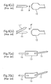
- Figures 6(a) & 6(b) each schematically show the arrangement of the tip area of the electrode, enlarged.
- a cathode 11 and an anode 12 opposite at a small distance from one another.
- an arc bright spot P is formed between the two electrodes.
- the cathode 11' is shifted (the position deviates from a given position).
- the distance to the anode 12 is increased, i.e., the distance between the electrodes.
- the position of the arc bright spot P' changes.
- Such a change of the electrode distance and the position of the arc bright spot reduces the efficiency of the light to a large degree because a projector device or the like is optically engineered based on given adjustment values.
- Figures 7(a) & (b) each schematically show the electrode displacement.
- Figure 7(a) shows the state in which the cathode on the metal foil is shifted during resistance welding of the cathode 11 to the metal foil 13, due to contact of the welding rod with the cathode or the metal foil. Since the diameter of the cathode is 0.2 mm to 1.0 mm, therefore, is extremely small, as was described above, the cathode often moves during contact with the welding rod.
- Figure 7(b) shows the state in which the cathode tip is also shifted as a result of bending of the metal foil itself. This occurs in a process in which the electrode assembly, after resistance welding of the metal foil to the cathode, is hermetically sealed in silica glass. The metal foil bends due to the flow property of the silica glass in the molten state. This description above relates above to the cathode, but it likewise applies to the anode.
- a primary object of the present invention is to reduce and prevent electrode displacement in a short-arc, ultra-high pressure mercury lamp with an extremely small electrode distance of 0.5 mm to 2.0 mm and a pressure within the arc tube of at least 150 atm during operation, and at the same time, to devise an arrangement of the side tube parts with good adhesive properties.
- the object is furthermore achieved in accordance with the invention in that the maximum height of the middle valley area of the metal foil with an essentially inverted W shape is 0.2 mm to 1.0 mm, when the diameter of the above described electrode is 0.2 mm to 1.0 mm and the outside diameter of the respective side tube part is 4.0 mm to 9.0 mm.
- FIG. 1 shows the overall arrangement of a short-arc, ultra-high pressure discharge lamp (hereinafter also called only a "discharge lamp") in accordance with the invention.
- the discharge lamp 1 has an essentially rugbyball-shaped (i.e., generally ellipsoid-shaped) light emitting part 2 which is formed from a silica glass discharge vessel.
- a side tube part 3 extends from each of opposite ends of the light emitting part 2, and a conductive metal foil 8, which normally is made of molybdenum, is hermetically sealed within each side tube part 3, for example, by a pinch seal.
- the ends of the electrode rods 6a, 7a which have the cathode 6 or the anode 7 on their tip are each located welded onto one end of a respective metal foil 8 so as to be electrically connected thereto.
- An outer lead 9, which projects to the outside, is welded to the other end of the respective metal foil 8.
- the cathode 6 and the anode 7 each have at a tip part with an increased diameter, and also a case in which they do not have a part with an increasing diameter at the respective tip. Furthermore, there are also cases in which the electrode includes the electrode rods 6a, 7a as part thereof.
- the term "electrode" as used herein is intended to encompass all such cases.
- the light emitting part 2 is filled with mercury, a rare gas, and if necessary, also a halogen gas.
- the mercury is used to obtain the desired wavelengths of visible radiation, for example, radiant light with wavelengths from 360 to 780 nm, and is added in an amount of at least 0.15 mg/mm 3 , for example, of 0.17 mg/mm 3 , 0.20 mg/mm 3 , 0.25 mg/mm 3 , or 0.30 mg/mm 3 .
- the values given here are for filling at room temperature and relate to the inside volume of the arc tube in mm 3 . This added amount also differs depending on the temperature condition. However, during operation, a pressure of at least 150 atm, therefore an extremely high vapor pressure, is reached.
- a discharge lamp with a high mercury vapor pressure during operation of at least 200 atm or at least 300 atm can be produced. The higher the mercury vapor pressure, the more suitable will the lamp be for use as a light source for a projector device.
- Iodine, bromine, chlorine, and the like in the form of a compound with mercury and other metals are added as the halogen.
- the amount of halogen added can be selected, for example, from the range of 10 -6 to 10 -2 ⁇ mol/mm 3 .
- the function of the halogen is to prolong the service life using the halogen cycle. For an extremely small discharge lamp with a high inner pressure, like the discharge lamp according to the invention, by adding halogen in this way, blackening and devitrification of the discharge lamp can be prevented.
- This short-arc, ultra-high pressure discharge lamp is located in a small projector device or the like.
- the overall arrangement is very small but, on the other hand, there is a need for a large amount of light.
- the thermal conditions within the light emitting part are therefore extremely strict, i.e., the value of the wall load is 0.8 W/mm 2 to 2.0 W/mm 2 , specifically 1.5 W/mm 2 .
- the lamp is installed in the above described projector device or in a presentation apparatus, such as an overhead projector, and can offer radiant light with good color reproduction.
- Figure 2(a) shows an electrode assembly having an electrode rod 6a, a metal foil 8 and an outer lead 9.
- Figure 2(b) shows the cross sectional shape of the metal foil 8.
- the metal foil 8 has an essentially inverted W shape (in spite of the arc shape), the term inverted W-shape being intended to encompass the serpentine or sinusoidal shape having two arches or peaks 82 and an interposed valley or trough 81 as shown in Fig. 2(b), in addition to the traditional W shape shown in Fig. 5(c) and the trapezoidal and rectangular wave shapes of Figs. 5(a) and 5(b) as well as other comparable peak and valley shapes.
- the electrode rod 6a and the outer lead 9 are each located in the middle valley area 81 and are welded to the metal foil.
- the electrode rod 6a advantageously sits in the middle of the valley area 81 of the metal foil 8, even if, when the electrode rods 6a are welded to the metal foil, a welding rod is pressed against both.
- the undesirable displacement which is described with reference to the prior art, therefore, does not occur.
- the width W of the central valley area 81 is 0.2 mm to 1.0 mm and its height H is 0.2 mm to 1.0 mm, as is described below.
- Figure 3 shows the state in which the electrode rod 6a is welded to the metal foil 8 by resistance welding.
- the electrode rod 6a and the metal foil 8 are located in a template 30 which has a given shape, and resistance welding is performed by pressing the upper welding rod 31 and the lower welding rod 32 against the electrode rod 6 and the metal foil 8.
- the reason why the lower welding rod 32 is thinner is to make the welding area smaller because it is desirable for the welding area to be at most 0.3 mm 3 .
- the reason for this is the following:
- the electrode rod 6a is advantageously held in the valley area 81 in the middle of the metal foil 8 with an inverted W shape. Thus, displacement of the electrode rod 6a can be prevented.
- the outer lead can be placed in the valley area of the metal foil. This has the same effect as in the electrode rod.
- the cathode rod was described.
- the invention is not limited to the cathode rod, the invention also being usable for the anode rod.
- Figure 4(a) and 4(b) each show formation of stress in hermetic sealing of a metal foil in the silica glass. Only the metal foil and electrode rod, and not the silica glass, is shown.
- Figure 4(a) shows the case of using a metal foil in accordance with the invention using a foil with an inverted W shape.
- Figure 4(b) shows the case of a conventional, plate-shaped metal foil.
- Figure 5(a) to 5(c) each show another embodiment of a metal foil with an inverted W shape.
- the central valley area 81 is trapezoidal.
- the arched areas 82 on opposite sides thereof are also trapezoidal.
- the central valley area 81 is rectangular.
- the arched areas 82 on opposite sides thereof are also rectangular.
- the central valley area 81 is sharp-cornered as are the arched areas 82 on opposite sides thereof.
- the foil 8 has a traditional W shape in cross section that has been inverted.
- the cross section of the metal foil of the invention has any essentially inverted W shape, including a wave shape as shown in Figure 2(a) and 2(b), the above described trapezoidal shape, the above described rectangular shape, or a traditional W shape, and also other shapes as was noted above.
- the valley area 81 in the middle of the metal foil of the invention is absolutely necessary for the purposes of arrangement of the electrode rod, and the arched areas 82 on opposite sides of the valley area are necessary for purposes of balancing during welding.
- the sides of the ached areas 82 can be provided with other shapes when such an essentially inverted W shape is partially present.
- the outside diameter of the respective side tube part, the outside diameter of the respective electrode rod, the inner volume of the arc tube and the like are to a certain extent limited.
- the outside diameter of the respective side tube part is 4.0 mm to 9.0 mm and the outside diameter of the respective electrode rod is 0.2 mm to 1.0 mm.
- the height H of the valley area of the metal foil of the invention is 0.2 mm to 1.0 mm and the width W is 0.2 mm to 1.0 mm. The reason for this is that there is no contact with the welding rod in resistance welding and therefore the metal foil is not scratched when the height H of the valley area of the metal foil is at most equal to the outside diameter of the electrode rod.
- the eccentricity represents the difference in distance between the two electrode tips in the direction perpendicular to the lengthwise direction of the lamp (direction B in Figure 1).
- Figures 8(a) and 8(b) show the results.
- the average electrode distance is 1.05 mm, its maximum value is 1.12 mm and its minimum value is 0.99 mm, while in the discharge lamps using the conventional metal foil, the average electrode distance is 0.77 mm, its maximum value is 0.98 mm and its minimum value is 0.58 mm. This shows that the variance of the indicated values is extremely small for the discharge lamps using the metal foil of the invention.
- Figures 9(a) and 9(b) show the results.
- the average of the relative values is 143, its maximum value is 186 and its minimum value is 120, while for the semi-finished product using the conventional metal foil, the average of the relative values is 101, its maximum value is 114 mm and its minimum value is 88.
- the adhesion of the metal foil to the silica glass is increased and that, as a result, the pressure tightness increases enormously.
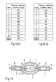
- FIG. 10 schematically shows the discharge lamp of that patent application.
- the light emitting part is filled with at least 0.15 mg/mm 3 mercury and a gap 10 is formed in the side tube part 3 on the outside surfaces of the cathode rod 6a and the anode rod 7a.
- the reason for formation of the gap 10 is the following:
- the gap is formed in order to free the relative expansion of the two materials relative to one another.
- the width of the gap is roughly 5 ⁇ m to 20 ⁇ m.
- the high pressure of the emission part is applied directly to the connecting site between the electrode rod and the metal foil. Therefore, it is useful to use the arrangement of the metal foil of the present invention.
- the metal foil which is hermetically sealed in the side tube part has an inverted W-shaped cross section.
Landscapes
- Engineering & Computer Science (AREA)
- Manufacturing & Machinery (AREA)
- Vessels And Coating Films For Discharge Lamps (AREA)
- Discharge Lamp (AREA)
Applications Claiming Priority (2)
| Application Number | Priority Date | Filing Date | Title |
|---|---|---|---|
| JP2001378676 | 2001-12-12 | ||
| JP2001378676A JP2003178714A (ja) | 2001-12-12 | 2001-12-12 | ショートアーク型超高圧放電ランプ |
Publications (2)
| Publication Number | Publication Date |
|---|---|
| EP1320120A2 true EP1320120A2 (de) | 2003-06-18 |
| EP1320120A3 EP1320120A3 (de) | 2003-10-15 |
Family
ID=19186332
Family Applications (1)
| Application Number | Title | Priority Date | Filing Date |
|---|---|---|---|
| EP02027711A Withdrawn EP1320120A3 (de) | 2001-12-12 | 2002-12-10 | Kurzbogenhochdruckentladungslampe |
Country Status (4)
| Country | Link |
|---|---|
| US (1) | US6911775B2 (de) |
| EP (1) | EP1320120A3 (de) |
| JP (1) | JP2003178714A (de) |
| CN (1) | CN1424741A (de) |
Cited By (1)
| Publication number | Priority date | Publication date | Assignee | Title |
|---|---|---|---|---|
| EP2221851A4 (de) * | 2007-12-12 | 2011-05-11 | Harison Toshiba Lighting Corp | Entladungslampe |
Families Citing this family (8)
| Publication number | Priority date | Publication date | Assignee | Title |
|---|---|---|---|---|
| JP3570414B2 (ja) * | 2002-03-05 | 2004-09-29 | ウシオ電機株式会社 | ショートアーク型超高圧放電ランプ |
| JP4614696B2 (ja) * | 2004-06-24 | 2011-01-19 | Hoya株式会社 | グレートーンマスクの製造方法 |
| JP4325518B2 (ja) * | 2004-09-10 | 2009-09-02 | ウシオ電機株式会社 | 超高圧水銀ランプ |
| DE202004014711U1 (de) * | 2004-09-21 | 2005-11-10 | Patent-Treuhand-Gesellschaft für elektrische Glühlampen mbH | Elektrische Lampe, die mittels Folienabdichtung verschlossen ist |
| JP2008027698A (ja) * | 2006-07-20 | 2008-02-07 | Osram-Melco Ltd | 超高圧水銀ランプ |
| JP4229166B2 (ja) * | 2006-10-16 | 2009-02-25 | セイコーエプソン株式会社 | 発光管、光源装置、及びプロジェクタ |
| JP5365799B2 (ja) * | 2009-10-23 | 2013-12-11 | ウシオ電機株式会社 | 高圧放電ランプおよび高圧放電ランプの製造方法 |
| CN103021792A (zh) * | 2012-12-31 | 2013-04-03 | 悍飞照明科技股份有限公司 | 一种超高压投影灯 |
Family Cites Families (13)
| Publication number | Priority date | Publication date | Assignee | Title |
|---|---|---|---|---|
| DE3813421A1 (de) * | 1988-04-21 | 1989-11-02 | Philips Patentverwaltung | Hochdruck-quecksilberdampfentladungslampe |
| US5497049A (en) | 1992-06-23 | 1996-03-05 | U.S. Philips Corporation | High pressure mercury discharge lamp |
| US5430353A (en) * | 1993-07-22 | 1995-07-04 | General Electric Company | Lamp inlead assembly having a formed foil arrangement |
| JPH08212978A (ja) * | 1995-02-08 | 1996-08-20 | Toshiba Lighting & Technol Corp | 高圧放電灯およびこれを有する点灯装置,プロジェクタ |
| JP3446529B2 (ja) | 1997-04-02 | 2003-09-16 | ウシオ電機株式会社 | 高圧放電ランプ |
| JPH1116539A (ja) * | 1997-06-24 | 1999-01-22 | Seiko Epson Corp | 光源ランプおよび光源ランプユニット |
| JP3298466B2 (ja) | 1997-07-17 | 2002-07-02 | ウシオ電機株式会社 | ショートアーク型放電ランプ、およびその製造方法 |
| JPH1167154A (ja) * | 1997-08-11 | 1999-03-09 | Ushio Inc | ショートアーク型超高圧放電ランプ |
| JPH11111226A (ja) | 1997-09-30 | 1999-04-23 | Ushio Inc | ショートアーク型超高圧放電ランプ |
| JP2000123786A (ja) * | 1998-10-13 | 2000-04-28 | Matsushita Electronics Industry Corp | 高圧水銀ランプ、この高圧水銀ランプを用いた照明光学装置、およびこの照明光学装置を用いた画像表示装置 |
| JP3085303B1 (ja) * | 1999-07-05 | 2000-09-04 | ウシオ電機株式会社 | 放電ランプ |
| JP3149874B1 (ja) | 1999-10-18 | 2001-03-26 | ウシオ電機株式会社 | ショートアーク型高圧水銀ランプ |
| JP3503575B2 (ja) | 2000-06-06 | 2004-03-08 | ウシオ電機株式会社 | ショートアーク型超高圧放電ランプ及びその製造方法 |
-
2001
- 2001-12-12 JP JP2001378676A patent/JP2003178714A/ja active Pending
-
2002
- 2002-12-10 EP EP02027711A patent/EP1320120A3/de not_active Withdrawn
- 2002-12-11 US US10/315,942 patent/US6911775B2/en not_active Expired - Fee Related
- 2002-12-12 CN CN02155862.0A patent/CN1424741A/zh active Pending
Cited By (2)
| Publication number | Priority date | Publication date | Assignee | Title |
|---|---|---|---|---|
| EP2221851A4 (de) * | 2007-12-12 | 2011-05-11 | Harison Toshiba Lighting Corp | Entladungslampe |
| US8339023B2 (en) | 2007-12-12 | 2012-12-25 | Harison Toshiba Lighting Corp. | Discharge lamp |
Also Published As
| Publication number | Publication date |
|---|---|
| JP2003178714A (ja) | 2003-06-27 |
| EP1320120A3 (de) | 2003-10-15 |
| CN1424741A (zh) | 2003-06-18 |
| US6911775B2 (en) | 2005-06-28 |
| US20030107320A1 (en) | 2003-06-12 |
Similar Documents
| Publication | Publication Date | Title |
|---|---|---|
| US6903509B2 (en) | Ultrahigh pressure discharge lamp of the short arc type with improved metal foil to electrode connection arrangement | |
| US6911775B2 (en) | Short-arc, ultra-high pressure discharge lamp | |
| US6861806B2 (en) | Super-high pressure discharge lamp of the short arc type | |
| JP4681668B2 (ja) | 箔シールランプ | |
| US6713957B2 (en) | Super-high pressure discharge lamp of the short arc type | |
| EP2221851A1 (de) | Entladungslampe | |
| US7176631B2 (en) | Ultra high pressure discharge lamp | |
| EP1324373B1 (de) | Superhochdruck-Entladungslampe vom Kurzbogentyp | |
| JP4301892B2 (ja) | 金属蒸気放電ランプおよび照明装置 | |
| JP4431174B2 (ja) | 高圧ガス放電ランプ | |
| JPH11111226A (ja) | ショートアーク型超高圧放電ランプ | |
| US7656093B2 (en) | Discharge lamp and metal foil for a discharge lamp | |
| JP4193540B2 (ja) | ショートアーク型超高圧放電ランプ | |
| JPH1167154A (ja) | ショートアーク型超高圧放電ランプ | |
| EP1107286A1 (de) | Hochdruck-Quecksilberdampfentladungslampe | |
| JPH11162407A (ja) | 放電ランプ及び光源装置 | |
| JP2002358927A (ja) | 高圧放電ランプおよび液晶表示装置 | |
| JP2004071499A (ja) | 高圧水銀ランプ | |
| JP2006344404A (ja) | 高圧放電ランプ |
Legal Events
| Date | Code | Title | Description |
|---|---|---|---|
| PUAI | Public reference made under article 153(3) epc to a published international application that has entered the european phase |
Free format text: ORIGINAL CODE: 0009012 |
|
| AK | Designated contracting states |
Designated state(s): AT BE BG CH CY CZ DE DK EE ES FI FR GB GR IE IT LI LU MC NL PT SE SI SK TR |
|
| AX | Request for extension of the european patent |
Extension state: AL LT LV MK RO |
|
| PUAL | Search report despatched |
Free format text: ORIGINAL CODE: 0009013 |
|
| AK | Designated contracting states |
Kind code of ref document: A3 Designated state(s): AT BE BG CH CY CZ DE DK EE ES FI FR GB GR IE IT LI LU MC NL PT SE SI SK TR |
|
| AX | Request for extension of the european patent |
Extension state: AL LT LV MK RO |
|
| RIC1 | Information provided on ipc code assigned before grant |
Ipc: 7H 01J 9/32 B Ipc: 7H 01J 5/38 B Ipc: 7H 01J 61/86 B Ipc: 7H 01J 61/36 A |
|
| 17P | Request for examination filed |
Effective date: 20031111 |
|
| STAA | Information on the status of an ep patent application or granted ep patent |
Free format text: STATUS: THE APPLICATION HAS BEEN WITHDRAWN |
|
| 18W | Application withdrawn |
Effective date: 20040513 |
|
| AKX | Designation fees paid |
Designated state(s): DE GB NL |