EP1320160A1 - Goulotte électrique à moyens de retenue de câbles ou de conducteurs électriques - Google Patents
Goulotte électrique à moyens de retenue de câbles ou de conducteurs électriques Download PDFInfo
- Publication number
- EP1320160A1 EP1320160A1 EP02292991A EP02292991A EP1320160A1 EP 1320160 A1 EP1320160 A1 EP 1320160A1 EP 02292991 A EP02292991 A EP 02292991A EP 02292991 A EP02292991 A EP 02292991A EP 1320160 A1 EP1320160 A1 EP 1320160A1
- Authority
- EP
- European Patent Office
- Prior art keywords
- base
- flexible wall
- edge
- flexible
- partition
- Prior art date
- Legal status (The legal status is an assumption and is not a legal conclusion. Google has not performed a legal analysis and makes no representation as to the accuracy of the status listed.)
- Granted
Links
- 239000004020 conductor Substances 0.000 claims abstract description 29
- 238000005192 partition Methods 0.000 claims description 38
- 239000000463 material Substances 0.000 claims description 14
- 238000000465 moulding Methods 0.000 claims description 8
- 238000001125 extrusion Methods 0.000 claims description 4
- 230000015572 biosynthetic process Effects 0.000 claims description 3
- 229920003052 natural elastomer Polymers 0.000 claims description 3
- 229920001194 natural rubber Polymers 0.000 claims description 3
- 238000000926 separation method Methods 0.000 claims description 3
- 229920003051 synthetic elastomer Polymers 0.000 claims description 3
- 238000004026 adhesive bonding Methods 0.000 claims description 2
- 239000012780 transparent material Substances 0.000 claims description 2
- 238000009434 installation Methods 0.000 abstract 1
- 239000011324 bead Substances 0.000 description 2
- 208000027418 Wounds and injury Diseases 0.000 description 1
- 230000003213 activating effect Effects 0.000 description 1
- 244000245420 ail Species 0.000 description 1
- 238000012550 audit Methods 0.000 description 1
- 230000006378 damage Effects 0.000 description 1
- 230000003028 elevating effect Effects 0.000 description 1
- 208000014674 injury Diseases 0.000 description 1
- 230000014759 maintenance of location Effects 0.000 description 1
- 229920000915 polyvinyl chloride Polymers 0.000 description 1
- 230000000284 resting effect Effects 0.000 description 1
- 229920002725 thermoplastic elastomer Polymers 0.000 description 1
- 210000002105 tongue Anatomy 0.000 description 1
- 210000003462 vein Anatomy 0.000 description 1
- 238000003466 welding Methods 0.000 description 1
Images

Classifications
-
- H—ELECTRICITY
- H02—GENERATION; CONVERSION OR DISTRIBUTION OF ELECTRIC POWER
- H02G—INSTALLATION OF ELECTRIC CABLES OR LINES, OR OF COMBINED OPTICAL AND ELECTRIC CABLES OR LINES
- H02G3/00—Installations of electric cables or lines or protective tubing therefor in or on buildings, equivalent structures or vehicles
- H02G3/02—Details
- H02G3/04—Protective tubing or conduits, e.g. cable ladders or cable troughs
- H02G3/0437—Channels
- H02G3/045—Channels provided with perforations or slots permitting introduction or exit of wires
Definitions
- the present invention relates generally to chutes electrics of the type used, for example for the support, the housing and protection of various electrical equipment, as well as for supporting, housing and protecting cables or conductors necessary to serve these devices.
- Such electric trunking includes a base provided with a longitudinal opening defined between the edges of two side wings longitudinal or a side wing and a partition wall or two partition walls that rise from a bottom, means of retaining cables or electrical conductors positioned inside said base, and a closing cover intended to be mounted on the base in covering said retaining means to close each opening longitudinal.
- Some already known electric trunking includes, in the angled returns of the longitudinal side wings of their base, cutouts locally forming rigid retaining fingers which extend into the opening longitudinal of said base, transverse to its longitudinal axis.
- These rigid retaining fingers act as retaining means for cables or electrical conductors.
- these rigid retaining fingers have a length relatively short and, once filling the base with cables or conductors exceeds the level of the ends of said fingers, these do not more function of retaining means for cables or electric conductors added later in the base of the chute.
- Some staples hang on the two square returns of said side wings, others hang only on the square back of a lateral wing of the base of the chute.
- said staples extend transversely to the longitudinal axis of the base of the chute, locally forming a bridge between the angled returns of the longitudinal side wings thereof.
- these clips are generally fixed by one end to a right angle return of a wing lateral of said base. Then, after the base of the chute has been completely filled with cables or electrical conductors, the other end of each clip is attached to the other square return of the other side wing of the base of the chute.
- some staples When activating the staples, some staples may be detach from the angled return from the side wing to which they are attached. Successive actuation of the various clips slows the installer in his trunking base wiring operation.
- These wiring conduits do not include means for retaining cables separate from the partial or total closing elements of the base.
- the present invention provides a new electric chute as defined in the introduction, characterized in that said means of retainers include at least one flexible wall, which runs along the edge of a said lateral wings or a partition separating the base, and which extends to the less in part substantially parallel to the bottom of said base in the direction of the other side wing or the other partition to cover at least partially each longitudinal opening of the base.
- each wall flexible forming the cable retention means retains the cables inserted in said base while allowing a user to easily introduce other cables to inside the base and when the chute is closed by its cover closing, access security is guaranteed by the latter superimposed on said means of restraint.
- FIGS. 1-10 show different embodiments of a electric trunking which includes a base 10, here in U-section, with a bottom 11 to from which rise two longitudinal side wings 12, 13 perpendicular to said bottom.
- the base has a V-shaped section with the two longitudinal side wings which diverge from the bottom or any other form of section.
- This longitudinal opening 10a is intended to be closed by a cover of closure 30 (see Figure 12).
- the longitudinal side wings 12, 13 of the base 10 at the top have square returns 14, 15 directed towards each other.
- Each groove longitudinal 16, 17 is surmounted by a longitudinal bead 18, 19.
- the beads longitudinal 18, 19 and the associated longitudinal grooves 16, 17 serve to the locking cover snaps onto the base 10.
- the means for mounting the closing cover 30 comprise on the base 10 a longitudinal groove 16, 17 provided for the recess of the external face of each longitudinal side wing 12, 13.
- the cover for closing the base 10 is overlapping, that is to say that it partially covers the external faces of the longitudinal lateral wings 12, 13 of this one.
- the wings longitudinal sides 12, 13 of the base 10 of the electrical trunking are free back to square and end with a free straight end edge 14a, 15a which extends along the axis X of the base 10.
- the means for mounting the closure cover 30 also comprise on the base 10 a longitudinal groove 16, 17 provided for the recess of the face outer of each longitudinal side wing 12, 13.
- a partition 12 ' which rises from the bottom 11 of the base 10 for divide its interior volume into two separate compartments.
- This partition of separation 12 ' carries two 12 "angle returns at the head which extend into opposite directions.
- This base 10 then has two longitudinal openings 10a elongated along the X axis, one per compartment.
- the electrical trunking shown in the figures includes means for retaining cables or electrical conductors (not shown) positioned inside the base 10.
- these retaining means comprise a flexible wall 20, which runs along the edge 15a of one of said longitudinal lateral wings 13 of the base 10, and which extends at least in part substantially parallel to the bottom 11 of said base 10 towards the other longitudinal side wing 12 to cover partially said longitudinal opening 10a of the base 10.
- each flexible wall 20 is attached to a square return 15 of the corresponding longitudinal side wing 13 of the base 10 and extends almost entirely parallel to the bottom 11 of the base.
- Each flexible wall 20 is substantially planar with at its base a offset 25 which is connected to the corresponding square return 15.
- This recess 25 is advantageous because it makes it possible to raise each flexible wall 20 above the plane of the longitudinal opening 10a of the base 10, which makes it possible to increase the cabling capacity of said base 10. Indeed, the installer can insert a few cables or conductors into this base electric above the base loading threshold defined by the sound plan longitudinal opening 10a, these cables or electrical conductors being maintained in place by said flexible walls 20.
- each flexible wall 20 is continuous along the edge 15a of the corresponding longitudinal lateral wing 13 of the base 10.
- the flexible wall 20 has a free edge 21 which follows a sinusoidal path whose vertices arrive at touching the other edge 14a of the other longitudinal side wing 12 and the recesses are located at a distance from this other edge 14a so that there is a gap 22 between the free edge 21 of the flexible wall 20 and the edge 14a of the other side wing longitudinal 12.
- This gap 22 allows the loading of cables or conductors electrical in the base 10 of the electrical trunking.
- the free edge 21 of the flexible wall 20 follows a straight path and is located at a distance from the other edge 14a of the other longitudinal side wing 12 of the base so that there is a gap 22 between the flexible wall 20 and the other longitudinal side wing 12 allowing the charging of cables or electrical conductors inside the base 10 of the electric chute.
- these means of retainers include a flexible wall 20 per compartment of the base 10, each compartment being defined between the partition wall 12 'and a side wing longitudinal 12, 13.
- Each flexible wall 20 runs along an edge 12 ′ a of said partition of separation 12 'and extends from a 12 "square return substantially parallel to the bottom 11 of the base in the direction of the longitudinal lateral wing 12, 13 corresponding so as to at least partially cover each opening longitudinal 10a.
- the two flexible walls 20 extend in directions opposite each other.
- each flexible wall 20 here follows a straight path in being slightly curved towards the inside of the base 10 to form a hook longitudinal improving the capacity to retain the cables introduced in each base compartment 10.
- each flexible wall 20 is continuous along the edge 12'a of the partition wall 12 '.
- the retaining means of the electrical trunking comprise two flexible walls 20 opposite, each running along an edge 14a, 15a of one of said lateral wings longitudinal 12, 13 of the base 10 and extending at least in part substantially parallel to the bottom 11 of said base in the direction of the other flexible wall 20 for partially cover said longitudinal opening 10a of the base 10, a gap 22 being provided between the two free edges 21 of said flexible walls 20 for allow loading through this gap 22 of cables or conductors inside the base 10 of the electrical trunking.
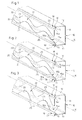
- Each of the flexible walls 20 of the bases 10 shown in Figures 1 and 2 is similar to the flexible wall of the base 10 shown in FIG. 7.
- Each flexible wall 20 comprises, near the longitudinal lateral wing 12, 13 to which it is attached, a recess 25 allowing to be slightly raised above the plane of the longitudinal opening 10a of the base 10, otherwise, for the most part, it extends parallel to the bottom 11 of the base 10.
- the free edges of the flexible walls 20 shown in Figures 1 and 2 also have a sinusoidal path so that the gap 22 defined between the two identical flexible walls 20 follows a sinuous path of width substantially constant.
- the flexible walls 20 shown in Figures 1 and 2 are also continuous along the edge 14a, 15a of the longitudinal lateral wing 12, 13 corresponding to said base 10.
- each flexible wall 20 is interrupted at places distributed regularly along the edge 14a, 15a of the corresponding longitudinal side wing 12, 13 of the base 10.
- each flexible wall 20 there is provided with a rigid part constituted by the return square 14, 15 corresponding to the longitudinal lateral wing 12, 13 of the base 10.
- Each piece of each wall flexible 20 has a profile identical to the profile of the flexible walls 20 shown in FIGS. 1, 2 and 7 with a free edge rounded along a portion of a sinusoid and a recess 25 attached to the edge 14a, 15a of the longitudinal lateral wing 12, 13 corresponding and a flat part extending parallel to the bottom 11 of the base 10.
- each flexible wall 20 opposite has a free edge 21 which follows a more accentuated sinusoidal path as the free edge of the flexible wall shown in Figure 7 so that here said free edge 21 comes, at each depression, tangent to the edge 14a, 15a of the lateral wing longitudinal 12, 13 corresponding to the base 10.
- each flexible wall 20 facing has a free edge 21 which follows a straight path, the width of the flexible walls 20 shown in FIG. 5 being less than the width of the flexible walls 20 shown in FIG. 6.
- the gap 22 provided between the two free edges 21 of the two flexible walls has a certain width while, according to the embodiment shown in Figure 6, the edges free 21 of the two flexible walls 20 facing each other are practically contiguous.
- each free edge 21 of each flexible wall 20 is curved towards the inside of the base 10 to form a longitudinal hook improving the ability to hold cables in inside the base 10.
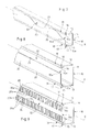
- FIGs 11 and 12 another embodiment of the base 10 of the electrical trunking according to the invention.
- the longitudinal side wings 12, 13 of the base 10 are free of back to square and end with a free straight end edge 14a, 15a.
- a flexible wall 20 ′ is attached to each of said straight free end edges 14a, 15a and has a right angle profile with a first part 20'a which extends in the extension of the corresponding longitudinal side wing 12, 13 and a second part 20'b extending at right angles to said first part 20'a substantially parallel to the bottom 11 of the base in the direction of the other flexible wall 20 '.
- a recess 25 ′ is provided identical to the step 25 previously described.
- This 25 'step increases the cabling capacity of the base 10 by slightly elevating each second 20'b plane part of each wall flexible 20 above the plane of the longitudinal opening 10a of the base 10.
- each flexible wall 20 ' is identical to the part plane of the flexible wall 20 shown for example in Figure 7 with an edge free 21 'which follows a sinusoidal path.
- Each second part 20'b of each wall flexible 20 ' extends here continuously along the first part 20'a of each wall flexible 20 '.
- each flexible wall 20' follows a path straight or in slots. It is also possible to have a single flexible wall 20 'on a single side wing of the base of the chute and nothing on the other side wing.
- a gap 22 allowing the easy loading of the base 10 in cables or electrical conductors.
- the base 10 shown in Figures 11 and 12 comprises, in each of the external faces of the longitudinal lateral wings 12, 13 rigid, one longitudinal groove 16, 17 for mounting the closing cover 30 (see figure 12).
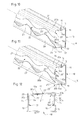
- one of the wings longitudinal side 12 of the base 10 is free from angle and is ends with a right end edge 14a while the other longitudinal side wing 13 has a square return 15 directed towards the other longitudinal side wing 12.
- the flexible walls 20 ′, 20, carried by the two lateral wings longitudinal 12, 13 of the base 10, are different, one of the flexible walls 20 ', attached to the right free end edge 14a of the longitudinal side wing 12 corresponding, having a right angle profile and being identical to the wall flexible 20 'described with reference to FIG. 11, while the other flexible wall 20, attached to the edge 15a of the square return 15 of the other longitudinal side wing 13, is identical to the flexible wall 20 described with reference to FIG. 7.
- Each flexible wall 20, 20 ' here also has a free edge which follows a sinusoidal path, a gap 22 being left between the two free edges 21, 21 '.
- each flexible wall 20 is attached to the edge 14a, 15a of the longitudinal lateral wing 12, 13 corresponding to the base 10 by means of mechanical mounting means.
- each flexible wall 20 is attached by fitting on the edge of the wing corresponding side of the base.
- each flexible wall is attached by snap-fastening on the edge of the corresponding lateral wing of the base or by riveting, by screwing, by stapling, gluing, welding or any other means of securing.
- each flexible wall 20, 20 ′ is formed by molding with the base 10.
- each flexible wall 20, 20 'and the base 10 are produced in one piece by co-extrusion of a rigid material constituting the base 10 and of a flexible material constituting each flexible wall 20, 20 '. This is the case for embodiments shown in Figures 1, 3 to 8 and 10 to 14.
- the flexible material which constitutes each flexible wall 20, 20 ′ is advantageously of the flexible PVC or synthetic or natural elastomer type.
- thermoplastic elastomer whose hardness is approximately equal to 80/90 shores A for the rigid base and is equal to approximately 60 shores A for the flexible walls.
- each flexible wall 20 and the base 10 are produced by molding the rigid material constituting the base, the flexibility of each flexible wall being obtained for example by cutting out this, after molding, into a plurality of tabs 20a juxtaposed according to the longitudinal direction X of said flexible wall 20.
- the edge 21 of the ends of the tongues 20a is here straight but may also follow a sinusoidal or niche path.
- the installer loads the bases 10 represented on the different figures by inserting electrical cables or conductors inside the gap defined between the flexible walls and resting on the flexible walls 20 which elastically deform to facilitate the passage of cables or electrical conductors.
- Each flexible wall 20 returns to its equilibrium state after that the cable or the electrical conductor has been introduced inside the base 10.
- the installer no longer needs to move an accessory from one hand restrain and pass the other electrical cables or conductors inside the chute base.
- the flexibility of the flexible walls 20 avoids the risk of injury to installer fingers. Once the base 10 of the chute electric is charged, the flexible walls 20 play their role of retaining means cables or electrical conductors inside said base having a elasticity adapted to be neither too soft nor too hard.
- each flexible wall may have an edge free following a path in slots.
- each flexible wall attached to a return in angle of the corresponding longitudinal side wing of the base, extends entirely parallel to the bottom of the base, that is to say that it does not include offset at its attachment to said return square.
- each flexible wall is provided on its free edge of attachment means on the other longitudinal side flange of the base of the chute so that the installer can lock it on said side wing after completing the filling of cables or electrical conductors basement.
Landscapes
- Engineering & Computer Science (AREA)
- Architecture (AREA)
- Civil Engineering (AREA)
- Structural Engineering (AREA)
- Details Of Indoor Wiring (AREA)
Abstract
Description
- chaque paroi souple est continue le long du bord de l'aile latérale ou de la cloison de séparation correspondante dudit socle ;
- chaque paroi souple est interrompue à des endroits répartis le long du bord de l'aile latérale ou de la cloison de séparation correspondante dudit socle ;
- chaque paroi souple présente un bord libre qui suit un trajet sinusoïdal ;
- chaque paroi souple présente un bord libre qui suit un trajet rectiligne ;
- chaque paroi souple présente un bord libre recourbé vers l'intérieur du socle pour former un crochet longitudinal ;
- chaque paroi souple présente un bord libre qui suit un trajet en créneaux ;
- le socle comprend au moins une cloison de séparation qui porte, le long de deux bords parallèles, deux parois souples qui s'étendent sensiblement parallèlement au fond du socle dans des directions opposées l'une de l'autre ;
- chaque paroi souple est rattachée à un retour en équerre de l'aile latérale ou de la cloison de séparation correspondante dudit socle et s'étend pratiquement entièrement parallèlement au fond du socle ;
- l'aile latérale ou la cloison de séparation correspondante dudit socle étant exempte de retour en équerre et se terminant par un bord d'extrémité libre droit, chaque paroi souple est rattachée audit bord d'extrémité libre droit ;
- chaque paroi souple présente un profil en angle droit avec une première partie s'étendant dans le prolongement de ladite aile latérale ou de ladite cloison de séparation et une deuxième partie s'étendant à l'équerre de ladite première partie parallèlement au fond du socle ;
- les moyens de retenue comprennent deux parois souples en regard, chacune courant le long du bord d'une desdites ailes latérales du socle et s'étendant au moins en partie sensiblement parallèlement au fond dudit socle en direction de l'autre paroi souple pour couvrir partiellement ladite ouverture longitudinale du socle, un interstice étant prévu entre les deux bords libres desdites parois souples ;
- les deux parois souples sont identiques ;
- les deux parois souples sont différentes ;
- chaque paroi souple vient de formation par moulage avec le socle ;
- chaque paroi souple et le socle sont réalisés d'un seul tenant par co-extrusion d'une matière rigide constituant le socle et d'une matière souple constituant chaque paroi souple ;
- chaque paroi souple est rapportée sur le bord de l'aile latérale ou de la cloison de séparation correspondante du socle par l'intermédiaire de moyens de montage mécanique ;
- chaque paroi souple est rapportée par encliquetage sur le bord de l'aile latérale ou de la cloison de séparation correspondante du socle ;
- chaque paroi souple est rapportée par emmanchement sur le bord de l'aile latérale ou de la cloison de séparation correspondante du socle ;
- chaque paroi souple est rapportée par collage sur le bord de l'aile latérale ou de la cloison de séparation correspondante du socle ;
- chaque paroi souple est soudée au bord de l'aile latérale ou de la cloison de séparation correspondante du socle ;
- chaque paroi souple et le socle sont réalisés par moulage d'une matière rigide, la souplesse de chaque paroi souple étant obtenue par découpage de celle-ci en une pluralité de languettes juxtaposées selon la direction longitudinale de ladite paroi souple ;
- chaque paroi souple est réalisée en une matière souple du type PVC souple ou élastomère synthétique ou naturel ;
- chaque paroi souple est réalisée en matière transparente ; et
- chaque paroi souple comporte, sur son bord libre, des moyens d'accrochage sur le bord de l'autre aile latérale longitudinale ou de l'autre cloison de séparation du socle pour être verrouillée.
- la figure 1 est une vue schématique partielle en perspective d'un socle d'un premier mode de réalisation de la goulotte électrique selon l'invention ;
- la figure 2 est une vue schématique partielle en perspective d'un socle d'un deuxième mode de réalisation de la goulotte électrique selon l'invention ;
- la figure 3 est une vue schématique partielle en perspective d'un socle d'un troisième mode de réalisation de la goulotte électrique selon l'invention ;
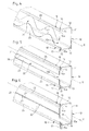
- la figure 4 est une vue schématique partielle en perspective d'un socle d'un quatrième mode de réalisation de la goulotte électrique selon l'invention ;
- la figure 5 est une vue schématique partielle en perspective d'un socle d'un cinquième mode de réalisation de la goulotte électrique selon l'invention ;
- la figure 6 est une vue schématique partielle en perspective d'un socle d'un sixième mode de réalisation de la goulotte électrique selon l'invention ;
- la figure 7 est une vue schématique partielle en perspective d'un socle d'un septième mode de réalisation de la goulotte électrique selon l'invention ;
- la figure 8 est une vue schématique partielle en perspective d'un socle d'un huitième mode de réalisation de la goulotte électrique selon l'invention ;
- la figure 9 est une vue schématique partielle en perspective d'un socle d'un neuvième mode de réalisation de la goulotte électrique selon l'invention ;
- la figure 10 est une vue schématique partielle en perspective d'un socle d'un dixième mode de réalisation de la goulotte électrique selon l'invention ;
- la figure 11 est une vue schématique partielle en perspective d'un socle d'un onzième mode de réalisation de la goulotte électrique selon l'invention ;
- la figure 12 est une vue en bout du socle représenté sur la figure 11 fermé par un couvercle ;
- la figure 13 est une vue schématique partielle en perspective d'un socle d'un douzième mode de réalisation de la goulotte électrique selon l'invention ; et
- la figure 14 est une vue schématique partielle en perspective d'un socle d'un treizième mode de réalisation de la goulotte électrique selon l'invention.
Claims (25)
- Goulotte électrique comprenant un socle (10) pourvu d'au moins une ouverture longitudinale (10a) définie entre les bords (14a, 15a) de deux ailes latérales longitudinales (12, 13) ou d'une aile latérale longitudinale (12, 13) et d'une cloison de séparation (12') ou encore de deux cloisons de séparation qui s'élèvent à partir d'un fond (11), des moyens de retenue (20) de câbles ou de conducteurs électriques positionnés à l'intérieur dudit socle (10) et un couvercle de fermeture (30) destiné à être monté sur le socle (10) en recouvrant lesdits moyens de retenue (20) pour fermer chaque ouverture longitudinale (10a), caractérisée en ce que lesdits moyens de retenue comprennent au moins une paroi souple (20), qui court le long du bord (15a ; 12'a) d'une desdites ailes latérales (13) ou d'une cloison de séparation (12') du socle (10), et qui s'étend au moins en partie sensiblement parallèlement au fond (11) dudit socle (10) en direction de l'autre aile latérale (12) ou de l'autre cloison de séparation pour couvrir au moins partiellement chaque ouverture longitudinale (10a) du socle (10).
- Goulotte selon la revendication 1, caractérisée en ce que chaque paroi souple (20) est continue le long du bord (14a, 15a ; 12'a) de l'aile latérale (12, 13) ou de la cloison de séparation (12') correspondante dudit socle (10).
- Goulotte selon la revendication 1, caractérisée en ce que chaque paroi souple (20) est interrompue à des endroits répartis le long du bord (14a, 15a) de l'aile latérale (12, 13) ou de la cloison de séparation correspondante dudit socle (10).
- Goulotte selon l'une des revendications 1 à 3, caractérisée en ce que chaque paroi souple (20) présente un bord libre (21) qui suit un trajet sinusoïdal.
- Goulotte selon l'une des revendications 1 à 3, caractérisée en ce que chaque paroi souple (20) présente un bord libre (21) qui suit un trajet rectiligne.
- Goulotte selon la revendication 5, caractérisée en ce que chaque paroi souple (20) présente un bord libre (21) recourbé vers l'intérieur du socle (10) pour former un crochet longitudinal.
- Goulotte selon l'une des revendications 1 à 3, caractérisée en ce que chaque paroi souple présente un bord libre qui suit un trajet en créneaux.
- Goulotte selon l'une des revendications 1 à 7 , caractérisée en ce que le socle (10) comprend au moins une cloison de séparation (12') qui porte, le long de deux bords (12'a) parallèles, deux parois souples (20) qui s'étendent sensiblement parallèlement au fond (11) du socle (10) dans des directions opposées l'une de l'autre.
- Goulotte selon l'une des revendications 1 à 8, caractérisée en ce que chaque paroi souple (20) est rattachée à un retour en équerre (14, 15 ; 12") de l'aile latérale (12, 13) ou de la cloison de séparation (12') correspondante dudit socle (10) et s'étend pratiquement entièrement parallèlement au fond (11) du socle (10).
- Goulotte selon l'une des revendications 1 à 8, caractérisé en ce que, l'aile latérale (12, 13) ou la cloison de séparation correspondante dudit socle (10) étant exempte de retour en équerre et se terminant par un bord d'extrémité libre droit (14a, 15a), chaque paroi souple (20') est rattachée audit bord d'extrémité libre droit (14a, 15a).
- Goulotte selon la revendication 10, caractérisée en ce que chaque paroi souple (20') présente un profil en angle droit avec une première partie (20'a) s'étendant dans le prolongement de ladite aile latérale (12, 13) ou de ladite cloison de séparation et une deuxième partie (20'b) s'étendant à l'équerre de ladite première partie (20'a) parallèlement au fond (11) du socle (10).
- Goulotte selon l'une des revendications précédentes, caractérisée en ce que les moyens de retenue comprennent deux parois souples (20) en regard, chacune courant le long du bord (14a, 15a) d'une desdites ailes latérales (12, 13) du socle (10) et s'étendant au moins en partie sensiblement parallèlement au fond (11) dudit socle (10) en direction de l'autre paroi souple (20) pour couvrir partiellement ladite ouverture longitudinale (10a) du socle, un interstice (22) étant prévu entre les deux bords libres (21) desdites parois souples (20).
- Goulotte selon la revendication 12, caractérisée en ce que les deux parois souples (20) sont identiques.
- Goulotte selon la revendication 12, caractérisée en ce que les deux parois souples (20, 20') sont différentes.
- Goulotte selon l'une des revendications 1 à 14, caractérisée en ce que chaque paroi souple (20, 20') vient de formation par moulage avec le socle.
- Goulotte selon la revendication 15, caractérisée en ce que chaque paroi souple (20, 20') et le socle (10) sont réalisés d'un seul tenant par co-extrusion d'une matière rigide constituant le socle (10) et d'une matière souple constituant chaque paroi souple (20, 20').
- Goulotte selon l'une des revendications 1 à 14, caractérisée en ce que chaque paroi souple (20) est rapportée sur le bord de l'aile latérale ou de la cloison de séparation correspondante du socle par l'intermédiaire de moyens de montage mécanique.
- Goulotte selon la revendication 17, caractérisée en ce que chaque paroi souple est rapportée par encliquetage sur le bord de l'aile latérale ou de la cloison de séparation correspondante du socle.
- Goulotte selon la revendication 17, caractérisée en ce que chaque paroi souple (20) est rapportée par emmanchement sur le bord de l'aile latérale ou de la cloison de séparation correspondante du socle.
- Goulotte selon l'une des revendications 1 à 14, caractérisée en ce que chaque paroi souple est rapportée par collage sur le bord de l'aile latérale ou de la cloison de séparation correspondante du socle.
- Goulotte selon l'une des revendications 1 à 14, caractérisée en ce que chaque paroi souple est soudée au bord de l'aile latérale ou de la cloison de séparation correspondante du socle.
- Goulotte selon la revendication 15, caractérisée en ce que chaque paroi souple (20) et le socle (10) sont réalisés par moulage d'une matière rigide, la souplesse de chaque paroi souple étant obtenue par découpage de celle-ci en une pluralité de languettes (20a) juxtaposées selon la direction longitudinale de ladite paroi souple (20).
- Goulotte selon l'une des revendications 1 à 22, caractérisée en ce que chaque paroi souple (20) est réalisée en une matière souple du type PVC souple ou élastomère synthétique ou naturel
- Goulotte selon l'une des revendications précédentes, caractérisée en ce que chaque paroi souple (20) est réalisée en une matière transparente.
- Goulotte selon l'une des revendications précédentes, caractérisée en ce que chaque paroi souple (20) comporte, sur son bord libre (21), des moyens d'accrochage sur le bord de l'autre aile latérale longitudinale ou de l'autre cloison de séparation du socle pour être verrouillée.
Applications Claiming Priority (2)
| Application Number | Priority Date | Filing Date | Title |
|---|---|---|---|
| FR0116222A FR2833771B1 (fr) | 2001-12-14 | 2001-12-14 | Goulotte electrique a moyens de retenue de cables ou de conducteurs electriques |
| FR0116222 | 2001-12-14 |
Publications (2)
| Publication Number | Publication Date |
|---|---|
| EP1320160A1 true EP1320160A1 (fr) | 2003-06-18 |
| EP1320160B1 EP1320160B1 (fr) | 2015-04-29 |
Family
ID=8870512
Family Applications (1)
| Application Number | Title | Priority Date | Filing Date |
|---|---|---|---|
| EP20020292991 Expired - Lifetime EP1320160B1 (fr) | 2001-12-14 | 2002-12-04 | Goulotte électrique à moyens de retenue de câbles ou de conducteurs électriques |
Country Status (5)
| Country | Link |
|---|---|
| EP (1) | EP1320160B1 (fr) |
| ES (1) | ES2543081T3 (fr) |
| FR (1) | FR2833771B1 (fr) |
| PL (1) | PL357740A1 (fr) |
| PT (1) | PT1320160E (fr) |
Cited By (8)
| Publication number | Priority date | Publication date | Assignee | Title |
|---|---|---|---|---|
| FR2968851A1 (fr) * | 2010-12-13 | 2012-06-15 | Cqfd Composites | Element de cheminement de cables electriques ou autres conduits similaires, et procede d’obtention d’un tel element |
| WO2013139449A3 (fr) * | 2012-03-19 | 2013-11-14 | Wolfgang Rixen | Elément de réception d'une canalisation |
| BE1025118B1 (nl) * | 2017-04-05 | 2018-11-07 | Vecotec Bvba | Hygiënische kabelhouder |
| GB2580125A (en) * | 2018-12-21 | 2020-07-15 | John Langford Garrett Timothy | A cable trough |
| US11258240B1 (en) * | 2019-07-11 | 2022-02-22 | James C. White Company, Inc. | Cable guides for use with cable trays |
| FR3117281A1 (fr) * | 2020-12-07 | 2022-06-10 | Arianegroup Sas | Goulotte de câbles électriques |
| US12206227B2 (en) | 2022-07-15 | 2025-01-21 | Schneider Electric USA, Inc. | Wire migration devices, systems, and methods |
| EP4651324A1 (fr) * | 2024-05-13 | 2025-11-19 | Alcom International GmbH | Conduit pour câbles |
Families Citing this family (1)
| Publication number | Priority date | Publication date | Assignee | Title |
|---|---|---|---|---|
| DE102019122500A1 (de) * | 2019-08-21 | 2021-02-25 | WASAG brush systems AG | Wand- oder Bodenleiste mit integriertem Kabelkanal und Verfahren zur Installation einer solchen Wand- oder Bodenleiste |
Citations (6)
| Publication number | Priority date | Publication date | Assignee | Title |
|---|---|---|---|---|
| DE1852065U (de) * | 1961-11-30 | 1962-05-24 | Bbc Brown Boveri & Cie | Leitungsfuehrungskanal. |
| CH368844A (de) * | 1958-06-07 | 1963-04-30 | Theysohn Albert | Kabelführungskanal |
| US4094561A (en) * | 1977-06-20 | 1978-06-13 | Harter Corporation | Wiring enclosure for desks |
| DE8412625U1 (de) * | 1984-04-24 | 1984-07-26 | Siemens AG, 1000 Berlin und 8000 München | Verdrahtungskanal |
| WO2001008280A2 (fr) * | 1999-07-23 | 2001-02-01 | Stuart Ashenhurst Ross | Porteur de cable |
| EP1160949A2 (fr) * | 2000-06-01 | 2001-12-05 | Panduit Corporation | Couvercle en fibres fendu et attache sur conduite pour cables |
-
2001
- 2001-12-14 FR FR0116222A patent/FR2833771B1/fr not_active Expired - Fee Related
-
2002
- 2002-12-04 PT PT2292991T patent/PT1320160E/pt unknown
- 2002-12-04 EP EP20020292991 patent/EP1320160B1/fr not_active Expired - Lifetime
- 2002-12-04 ES ES02292991.3T patent/ES2543081T3/es not_active Expired - Lifetime
- 2002-12-12 PL PL35774002A patent/PL357740A1/xx not_active Application Discontinuation
Patent Citations (6)
| Publication number | Priority date | Publication date | Assignee | Title |
|---|---|---|---|---|
| CH368844A (de) * | 1958-06-07 | 1963-04-30 | Theysohn Albert | Kabelführungskanal |
| DE1852065U (de) * | 1961-11-30 | 1962-05-24 | Bbc Brown Boveri & Cie | Leitungsfuehrungskanal. |
| US4094561A (en) * | 1977-06-20 | 1978-06-13 | Harter Corporation | Wiring enclosure for desks |
| DE8412625U1 (de) * | 1984-04-24 | 1984-07-26 | Siemens AG, 1000 Berlin und 8000 München | Verdrahtungskanal |
| WO2001008280A2 (fr) * | 1999-07-23 | 2001-02-01 | Stuart Ashenhurst Ross | Porteur de cable |
| EP1160949A2 (fr) * | 2000-06-01 | 2001-12-05 | Panduit Corporation | Couvercle en fibres fendu et attache sur conduite pour cables |
Cited By (11)
| Publication number | Priority date | Publication date | Assignee | Title |
|---|---|---|---|---|
| FR2968851A1 (fr) * | 2010-12-13 | 2012-06-15 | Cqfd Composites | Element de cheminement de cables electriques ou autres conduits similaires, et procede d’obtention d’un tel element |
| WO2012080644A1 (fr) * | 2010-12-13 | 2012-06-21 | Cqfd Composites | Elément de cheminement de câbles électriques ou autres conduits similaires, et procédé d' obtention d'un tel élément |
| WO2013139449A3 (fr) * | 2012-03-19 | 2013-11-14 | Wolfgang Rixen | Elément de réception d'une canalisation |
| BE1025118B1 (nl) * | 2017-04-05 | 2018-11-07 | Vecotec Bvba | Hygiënische kabelhouder |
| GB2580125A (en) * | 2018-12-21 | 2020-07-15 | John Langford Garrett Timothy | A cable trough |
| GB2580125B (en) * | 2018-12-21 | 2021-01-06 | John Langford Garrett Timothy | A cable trough |
| EP3793047A1 (fr) * | 2018-12-21 | 2021-03-17 | Timothy John Langford Garrett | Goulotte de câbles |
| US11258240B1 (en) * | 2019-07-11 | 2022-02-22 | James C. White Company, Inc. | Cable guides for use with cable trays |
| FR3117281A1 (fr) * | 2020-12-07 | 2022-06-10 | Arianegroup Sas | Goulotte de câbles électriques |
| US12206227B2 (en) | 2022-07-15 | 2025-01-21 | Schneider Electric USA, Inc. | Wire migration devices, systems, and methods |
| EP4651324A1 (fr) * | 2024-05-13 | 2025-11-19 | Alcom International GmbH | Conduit pour câbles |
Also Published As
| Publication number | Publication date |
|---|---|
| ES2543081T3 (es) | 2015-08-14 |
| FR2833771B1 (fr) | 2004-07-30 |
| PT1320160E (pt) | 2015-08-26 |
| EP1320160B1 (fr) | 2015-04-29 |
| FR2833771A1 (fr) | 2003-06-20 |
| PL357740A1 (en) | 2003-06-16 |
Similar Documents
| Publication | Publication Date | Title |
|---|---|---|
| EP1276197B1 (fr) | Accessoire pour goulotte à tronçons de hauteurs différentes | |
| EP0382597B1 (fr) | Profilé, tel que goulotte, plinthe, moulure ou autre, pour le logement et la protection, en particulier, d'appareillages électriques et des conducteurs nécessaires à la desserte de ceux-ci | |
| EP1119088B1 (fr) | Conduit de câblage électrique à multicompartiments présentant une grande capacité de câblage | |
| EP1094578A1 (fr) | Agrafe de retenue pour goulotte, notamment pour appareillages électriques | |
| EP1744423B1 (fr) | Goulotte de distribution à dispositif de réception d'un collier de serrage | |
| EP1320160B1 (fr) | Goulotte électrique à moyens de retenue de câbles ou de conducteurs électriques | |
| EP0986849B1 (fr) | Goulotte de cablage et accessoire susceptible d' etre rapporte sur une telle goulotte de cablage | |
| EP2540641B1 (fr) | Emballage pour baguettes de soudage à capuchon pivotant et mobile axialement, utilisation d'un emballage | |
| FR2796770A1 (fr) | Support d'appareillage electrique a rapporter sur une goulotte | |
| EP1139535B1 (fr) | Accessoire à rapporter sur un socle de goulotte de cheminement de conducteurs ou de câbles électriques. | |
| EP0838885B1 (fr) | Agrafe de retenue pour goulotte, et goulotte équipée d'une telle agrafe de retenue | |
| EP1164675B1 (fr) | Accessoire de dérivation positionné à la jonction de deux goulottes | |
| FR2799897A1 (fr) | Accessoire a rapporter sur un socle de goulotte de cheminement de cables electriques | |
| EP0921617B1 (fr) | Support pour appareillage à disposer le long d'une goulotte | |
| EP1158634B1 (fr) | Embout pour goulotte de cheminement de câbles ou de conducteurs électriques | |
| WO1997011519A1 (fr) | Embout pour goulotte de cheminement de conducteurs electriques | |
| EP1359653B1 (fr) | Elément constitutif d'une goulotte avec agrafes de retenue de câbles intégrées et goulotte comprenant un ou plusieurs éléments constitutifs de ce type | |
| EP1432091B1 (fr) | Accessoire de couplage pour socle de goulotte | |
| FR2768268A1 (fr) | Agrafe de retenue ,notamment pour goulotte destinee a des appareillages electriques | |
| FR3058109A1 (fr) | Dispositif de plancher pour vehicule et vehicule comprenant ce dispositif de plancher | |
| CH626472A5 (fr) | ||
| FR2666479A1 (fr) | Boite de montage pour appareil electrique. | |
| EP1085143A1 (fr) | Plinthe amovible permettant le passage de fils ou cables électriques | |
| FR2793078A1 (fr) | Cloison pour le compartimentage d'un socle de goulotte | |
| FR2684813A1 (fr) | Procede et barrette pour retenir des conducteurs flexibles dans une goulotte. |
Legal Events
| Date | Code | Title | Description |
|---|---|---|---|
| PUAI | Public reference made under article 153(3) epc to a published international application that has entered the european phase |
Free format text: ORIGINAL CODE: 0009012 |
|
| AK | Designated contracting states |
Designated state(s): AT BE BG CH CY CZ DE DK EE ES FI FR GB GR IE IT LI LU MC NL PT SE SI SK TR |
|
| AX | Request for extension of the european patent |
Extension state: AL LT LV MK RO |
|
| 17P | Request for examination filed |
Effective date: 20030621 |
|
| AKX | Designation fees paid |
Designated state(s): AT BE BG CH CY CZ DE DK EE ES FI FR GB GR IE IT LI LU MC NL PT SE SI SK TR |
|
| GRAP | Despatch of communication of intention to grant a patent |
Free format text: ORIGINAL CODE: EPIDOSNIGR1 |
|
| INTG | Intention to grant announced |
Effective date: 20141112 |
|
| GRAS | Grant fee paid |
Free format text: ORIGINAL CODE: EPIDOSNIGR3 |
|
| GRAA | (expected) grant |
Free format text: ORIGINAL CODE: 0009210 |
|
| AK | Designated contracting states |
Kind code of ref document: B1 Designated state(s): AT BE BG CH CY CZ DE DK EE ES FI FR GB GR IE IT LI LU MC NL PT SE SI SK TR |
|
| REG | Reference to a national code |
Ref country code: GB Ref legal event code: FG4D Free format text: NOT ENGLISH |
|
| REG | Reference to a national code |
Ref country code: CH Ref legal event code: EP |
|
| REG | Reference to a national code |
Ref country code: AT Ref legal event code: REF Ref document number: 724904 Country of ref document: AT Kind code of ref document: T Effective date: 20150515 |
|
| REG | Reference to a national code |
Ref country code: IE Ref legal event code: FG4D Free format text: LANGUAGE OF EP DOCUMENT: FRENCH |
|
| REG | Reference to a national code |
Ref country code: DE Ref legal event code: R096 Ref document number: 60247149 Country of ref document: DE Effective date: 20150611 |
|
| REG | Reference to a national code |
Ref country code: ES Ref legal event code: FG2A Ref document number: 2543081 Country of ref document: ES Kind code of ref document: T3 Effective date: 20150814 |
|
| REG | Reference to a national code |
Ref country code: PT Ref legal event code: SC4A Free format text: AVAILABILITY OF NATIONAL TRANSLATION Effective date: 20150706 |
|
| REG | Reference to a national code |
Ref country code: NL Ref legal event code: VDEP Effective date: 20150429 |
|
| REG | Reference to a national code |
Ref country code: AT Ref legal event code: MK05 Ref document number: 724904 Country of ref document: AT Kind code of ref document: T Effective date: 20150429 |
|
| PG25 | Lapsed in a contracting state [announced via postgrant information from national office to epo] |
Ref country code: NL Free format text: LAPSE BECAUSE OF FAILURE TO SUBMIT A TRANSLATION OF THE DESCRIPTION OR TO PAY THE FEE WITHIN THE PRESCRIBED TIME-LIMIT Effective date: 20150429 |
|
| PG25 | Lapsed in a contracting state [announced via postgrant information from national office to epo] |
Ref country code: FI Free format text: LAPSE BECAUSE OF FAILURE TO SUBMIT A TRANSLATION OF THE DESCRIPTION OR TO PAY THE FEE WITHIN THE PRESCRIBED TIME-LIMIT Effective date: 20150429 |
|
| PG25 | Lapsed in a contracting state [announced via postgrant information from national office to epo] |
Ref country code: GR Free format text: LAPSE BECAUSE OF FAILURE TO SUBMIT A TRANSLATION OF THE DESCRIPTION OR TO PAY THE FEE WITHIN THE PRESCRIBED TIME-LIMIT Effective date: 20150730 Ref country code: AT Free format text: LAPSE BECAUSE OF FAILURE TO SUBMIT A TRANSLATION OF THE DESCRIPTION OR TO PAY THE FEE WITHIN THE PRESCRIBED TIME-LIMIT Effective date: 20150429 |
|
| REG | Reference to a national code |
Ref country code: FR Ref legal event code: PLFP Year of fee payment: 14 |
|
| PG25 | Lapsed in a contracting state [announced via postgrant information from national office to epo] |
Ref country code: EE Free format text: LAPSE BECAUSE OF FAILURE TO SUBMIT A TRANSLATION OF THE DESCRIPTION OR TO PAY THE FEE WITHIN THE PRESCRIBED TIME-LIMIT Effective date: 20150429 Ref country code: DK Free format text: LAPSE BECAUSE OF FAILURE TO SUBMIT A TRANSLATION OF THE DESCRIPTION OR TO PAY THE FEE WITHIN THE PRESCRIBED TIME-LIMIT Effective date: 20150429 |
|
| REG | Reference to a national code |
Ref country code: DE Ref legal event code: R097 Ref document number: 60247149 Country of ref document: DE |
|
| PG25 | Lapsed in a contracting state [announced via postgrant information from national office to epo] |
Ref country code: CZ Free format text: LAPSE BECAUSE OF FAILURE TO SUBMIT A TRANSLATION OF THE DESCRIPTION OR TO PAY THE FEE WITHIN THE PRESCRIBED TIME-LIMIT Effective date: 20150429 Ref country code: SK Free format text: LAPSE BECAUSE OF FAILURE TO SUBMIT A TRANSLATION OF THE DESCRIPTION OR TO PAY THE FEE WITHIN THE PRESCRIBED TIME-LIMIT Effective date: 20150429 |
|
| PLBE | No opposition filed within time limit |
Free format text: ORIGINAL CODE: 0009261 |
|
| STAA | Information on the status of an ep patent application or granted ep patent |
Free format text: STATUS: NO OPPOSITION FILED WITHIN TIME LIMIT |
|
| 26N | No opposition filed |
Effective date: 20160201 |
|
| PG25 | Lapsed in a contracting state [announced via postgrant information from national office to epo] |
Ref country code: BE Free format text: LAPSE BECAUSE OF NON-PAYMENT OF DUE FEES Effective date: 20151231 Ref country code: SI Free format text: LAPSE BECAUSE OF FAILURE TO SUBMIT A TRANSLATION OF THE DESCRIPTION OR TO PAY THE FEE WITHIN THE PRESCRIBED TIME-LIMIT Effective date: 20150429 |
|
| PG25 | Lapsed in a contracting state [announced via postgrant information from national office to epo] |
Ref country code: MC Free format text: LAPSE BECAUSE OF FAILURE TO SUBMIT A TRANSLATION OF THE DESCRIPTION OR TO PAY THE FEE WITHIN THE PRESCRIBED TIME-LIMIT Effective date: 20150429 Ref country code: LU Free format text: LAPSE BECAUSE OF FAILURE TO SUBMIT A TRANSLATION OF THE DESCRIPTION OR TO PAY THE FEE WITHIN THE PRESCRIBED TIME-LIMIT Effective date: 20151204 |
|
| REG | Reference to a national code |
Ref country code: CH Ref legal event code: PL |
|
| REG | Reference to a national code |
Ref country code: IE Ref legal event code: MM4A |
|
| PG25 | Lapsed in a contracting state [announced via postgrant information from national office to epo] |
Ref country code: LI Free format text: LAPSE BECAUSE OF NON-PAYMENT OF DUE FEES Effective date: 20151231 Ref country code: CH Free format text: LAPSE BECAUSE OF NON-PAYMENT OF DUE FEES Effective date: 20151231 Ref country code: IE Free format text: LAPSE BECAUSE OF NON-PAYMENT OF DUE FEES Effective date: 20151204 |
|
| REG | Reference to a national code |
Ref country code: FR Ref legal event code: PLFP Year of fee payment: 15 |
|
| PGFP | Annual fee paid to national office [announced via postgrant information from national office to epo] |
Ref country code: DE Payment date: 20161221 Year of fee payment: 15 |
|
| PG25 | Lapsed in a contracting state [announced via postgrant information from national office to epo] |
Ref country code: BG Free format text: LAPSE BECAUSE OF FAILURE TO SUBMIT A TRANSLATION OF THE DESCRIPTION OR TO PAY THE FEE WITHIN THE PRESCRIBED TIME-LIMIT Effective date: 20150429 |
|
| PG25 | Lapsed in a contracting state [announced via postgrant information from national office to epo] |
Ref country code: CY Free format text: LAPSE BECAUSE OF FAILURE TO SUBMIT A TRANSLATION OF THE DESCRIPTION OR TO PAY THE FEE WITHIN THE PRESCRIBED TIME-LIMIT Effective date: 20150429 Ref country code: SE Free format text: LAPSE BECAUSE OF FAILURE TO SUBMIT A TRANSLATION OF THE DESCRIPTION OR TO PAY THE FEE WITHIN THE PRESCRIBED TIME-LIMIT Effective date: 20150429 |
|
| REG | Reference to a national code |
Ref country code: FR Ref legal event code: PLFP Year of fee payment: 16 |
|
| REG | Reference to a national code |
Ref country code: DE Ref legal event code: R119 Ref document number: 60247149 Country of ref document: DE |
|
| PG25 | Lapsed in a contracting state [announced via postgrant information from national office to epo] |
Ref country code: DE Free format text: LAPSE BECAUSE OF NON-PAYMENT OF DUE FEES Effective date: 20180703 |
|
| PGFP | Annual fee paid to national office [announced via postgrant information from national office to epo] |
Ref country code: PT Payment date: 20191120 Year of fee payment: 18 |
|
| PGFP | Annual fee paid to national office [announced via postgrant information from national office to epo] |
Ref country code: IT Payment date: 20191217 Year of fee payment: 18 |
|
| PGFP | Annual fee paid to national office [announced via postgrant information from national office to epo] |
Ref country code: TR Payment date: 20191127 Year of fee payment: 18 |
|
| PGFP | Annual fee paid to national office [announced via postgrant information from national office to epo] |
Ref country code: GB Payment date: 20191220 Year of fee payment: 18 Ref country code: ES Payment date: 20200124 Year of fee payment: 18 |
|
| PG25 | Lapsed in a contracting state [announced via postgrant information from national office to epo] |
Ref country code: PT Free format text: LAPSE BECAUSE OF NON-PAYMENT OF DUE FEES Effective date: 20210604 |
|
| GBPC | Gb: european patent ceased through non-payment of renewal fee |
Effective date: 20201204 |
|
| PG25 | Lapsed in a contracting state [announced via postgrant information from national office to epo] |
Ref country code: IT Free format text: LAPSE BECAUSE OF NON-PAYMENT OF DUE FEES Effective date: 20201204 |
|
| PG25 | Lapsed in a contracting state [announced via postgrant information from national office to epo] |
Ref country code: GB Free format text: LAPSE BECAUSE OF NON-PAYMENT OF DUE FEES Effective date: 20201204 |
|
| PGFP | Annual fee paid to national office [announced via postgrant information from national office to epo] |
Ref country code: FR Payment date: 20211118 Year of fee payment: 20 |
|
| REG | Reference to a national code |
Ref country code: ES Ref legal event code: FD2A Effective date: 20220207 |
|
| PG25 | Lapsed in a contracting state [announced via postgrant information from national office to epo] |
Ref country code: ES Free format text: LAPSE BECAUSE OF NON-PAYMENT OF DUE FEES Effective date: 20201205 |
|
| PG25 | Lapsed in a contracting state [announced via postgrant information from national office to epo] |
Ref country code: TR Free format text: LAPSE BECAUSE OF NON-PAYMENT OF DUE FEES Effective date: 20201204 |