EP1320165A2 - Appareil et méthode de protection de générateurs synchrones de déviations de fréquence nominal et de forces d'excitation alternatives - Google Patents
Appareil et méthode de protection de générateurs synchrones de déviations de fréquence nominal et de forces d'excitation alternatives Download PDFInfo
- Publication number
- EP1320165A2 EP1320165A2 EP02079811A EP02079811A EP1320165A2 EP 1320165 A2 EP1320165 A2 EP 1320165A2 EP 02079811 A EP02079811 A EP 02079811A EP 02079811 A EP02079811 A EP 02079811A EP 1320165 A2 EP1320165 A2 EP 1320165A2
- Authority
- EP
- European Patent Office
- Prior art keywords
- forcing
- actual
- generator
- frequency
- amount
- Prior art date
- Legal status (The legal status is an assumption and is not a legal conclusion. Google has not performed a legal analysis and makes no representation as to the accuracy of the status listed.)
- Granted
Links
- 238000000034 method Methods 0.000 title claims abstract description 20
- 230000005284 excitation Effects 0.000 title abstract description 30
- 230000001360 synchronised effect Effects 0.000 claims abstract description 16
- 230000005540 biological transmission Effects 0.000 abstract description 4
- 238000013461 design Methods 0.000 description 10
- 238000010586 diagram Methods 0.000 description 7
- 230000005611 electricity Effects 0.000 description 6
- 238000004804 winding Methods 0.000 description 6
- 238000010248 power generation Methods 0.000 description 5
- 238000000819 phase cycle Methods 0.000 description 4
- 230000008901 benefit Effects 0.000 description 3
- 238000012544 monitoring process Methods 0.000 description 3
- 230000008569 process Effects 0.000 description 3
- 230000004308 accommodation Effects 0.000 description 2
- 230000002350 accommodative effect Effects 0.000 description 2
- 238000004364 calculation method Methods 0.000 description 2
- 230000006870 function Effects 0.000 description 2
- 238000012986 modification Methods 0.000 description 2
- 230000004048 modification Effects 0.000 description 2
- 238000005381 potential energy Methods 0.000 description 2
- 230000001681 protective effect Effects 0.000 description 2
- 238000004422 calculation algorithm Methods 0.000 description 1
- 125000004122 cyclic group Chemical group 0.000 description 1
- 238000013016 damping Methods 0.000 description 1
- 230000005674 electromagnetic induction Effects 0.000 description 1
- 230000004907 flux Effects 0.000 description 1
- 239000002803 fossil fuel Substances 0.000 description 1
- 238000010438 heat treatment Methods 0.000 description 1
- 238000003475 lamination Methods 0.000 description 1
- 230000005577 local transmission Effects 0.000 description 1
- 230000007246 mechanism Effects 0.000 description 1
- 230000010355 oscillation Effects 0.000 description 1
- 238000013021 overheating Methods 0.000 description 1
- 230000009993 protective function Effects 0.000 description 1
- 238000004080 punching Methods 0.000 description 1
- 230000009467 reduction Effects 0.000 description 1
- 230000004044 response Effects 0.000 description 1
Images

Classifications
-
- H—ELECTRICITY
- H02—GENERATION; CONVERSION OR DISTRIBUTION OF ELECTRIC POWER
- H02H—EMERGENCY PROTECTIVE CIRCUIT ARRANGEMENTS
- H02H7/00—Emergency protective circuit arrangements specially adapted for specific types of electric machines or apparatus or for sectionalised protection of cable or line systems, and effecting automatic switching in the event of an undesired change from normal working conditions
- H02H7/06—Emergency protective circuit arrangements specially adapted for specific types of electric machines or apparatus or for sectionalised protection of cable or line systems, and effecting automatic switching in the event of an undesired change from normal working conditions for dynamo-electric generators; for synchronous capacitors
-
- H—ELECTRICITY
- H02—GENERATION; CONVERSION OR DISTRIBUTION OF ELECTRIC POWER
- H02H—EMERGENCY PROTECTIVE CIRCUIT ARRANGEMENTS
- H02H3/00—Emergency protective circuit arrangements for automatic disconnection directly responsive to an undesired change from normal electric working condition with or without subsequent reconnection ; integrated protection
- H02H3/46—Emergency protective circuit arrangements for automatic disconnection directly responsive to an undesired change from normal electric working condition with or without subsequent reconnection ; integrated protection responsive to frequency deviations
-
- H—ELECTRICITY
- H02—GENERATION; CONVERSION OR DISTRIBUTION OF ELECTRIC POWER
- H02H—EMERGENCY PROTECTIVE CIRCUIT ARRANGEMENTS
- H02H3/00—Emergency protective circuit arrangements for automatic disconnection directly responsive to an undesired change from normal electric working condition with or without subsequent reconnection ; integrated protection
- H02H3/26—Emergency protective circuit arrangements for automatic disconnection directly responsive to an undesired change from normal electric working condition with or without subsequent reconnection ; integrated protection responsive to difference between voltages or between currents; responsive to phase angle between voltages or between currents
- H02H3/28—Emergency protective circuit arrangements for automatic disconnection directly responsive to an undesired change from normal electric working condition with or without subsequent reconnection ; integrated protection responsive to difference between voltages or between currents; responsive to phase angle between voltages or between currents involving comparison of the voltage or current values at two spaced portions of a single system, e.g. at opposite ends of one line, at input and output of apparatus
- H02H3/30—Emergency protective circuit arrangements for automatic disconnection directly responsive to an undesired change from normal electric working condition with or without subsequent reconnection ; integrated protection responsive to difference between voltages or between currents; responsive to phase angle between voltages or between currents involving comparison of the voltage or current values at two spaced portions of a single system, e.g. at opposite ends of one line, at input and output of apparatus using pilot wires or other signalling channel
- H02H3/307—Emergency protective circuit arrangements for automatic disconnection directly responsive to an undesired change from normal electric working condition with or without subsequent reconnection ; integrated protection responsive to difference between voltages or between currents; responsive to phase angle between voltages or between currents involving comparison of the voltage or current values at two spaced portions of a single system, e.g. at opposite ends of one line, at input and output of apparatus using pilot wires or other signalling channel involving comparison of quantities derived from a plurality of phases, e.g. homopolar quantities; using mixing transformers
Definitions
- the present invention relates in general to the field of synchronous generators, and more particularly, to an apparatus and method for protecting synchronous generators from off-nominal frequency deviation coincident with alternating forces excitation.
- the present invention has particular application when used with generators within a power generator plant integrated into a power transmission grid system.
- Many power generation plants produce electricity by converting potential energy (e.g. fossil fuel) into mechanical energy (e.g. rotation of a turbine shaft), and then converting the mechanical energy into electrical energy (e.g. by the principles of electromagnetic induction). These power generation plants typically use a turbine to convert the potential energy into mechanical energy and a generator to convert the mechanical energy into electricity.
- potential energy e.g. fossil fuel
- mechanical energy e.g. rotation of a turbine shaft
- electrical energy e.g. by the principles of electromagnetic induction
- the electricity is then distributed from the power generation plants to consumers through power transmission grid systems, such as those extending throughout the United States and portions thereof.
- power transmission grid systems such as those extending throughout the United States and portions thereof.
- These power grids operate at a predefined nominal frequency, such as 60Hz in the United States and 50 Hz in Europe. This nominal frequency typically deviates by about +/- 0-5 Hz during normal power grid operation due to a variety or reasons such as peak demand, low electricity output, inadvertent loss of load, tripping of generators or lines, and power grid operator selection.
- Individual power generation plants may be required to operate at frequencies that deviate by about +/- 0-5 Hz from the power grid's nominal operating frequency (hereinafter "off-nominal frequency") to help compensate for line loads and other reasons.
- an off-nominal frequency relay is typically used to trip the generator to an off-line mode if the generator's off-frequency operation exceeds certain parameters that can otherwise lead to generator damage. For example, during underfrequency, it is possible to overexcite the core of the generator due to excessive Volts/Hertz excitation. This could lead to shorted laminations in the stator core. Also, since most generators are ventilated by a shaft-mounted blower and since some generators are excited by a shaft-mounted exciter, reductions in system frequency that lead to reduced speed of rotation may cause overheating of the generator or exciter.
- generator shafts often have torsional natural frequencies that are close to twice normal operating frequency, so operation at off-nominal frequencies coincident with high levels of local negative sequence excitation (which causes a double frequency torque to be applied to the rotor) may cause torsional fatigue of rotating components.
- generator design involves the accommodation of typical internal electrically based alternating forces excitation, such as negative sequence excitation and system harmonics, such as may be generated by electronic loads, arc furnaces, and HVDC power terminals.
- negative sequence relay is typically used to alarm the operator or trip the generator to an off-line mode if the generator's negative sequence excitation exceeds certain parameters that can otherwise lead to generator damage.
- Negative sequence currents in the generator cause a double-frequency torque on the generator rotor and cause eddy currents to flow on the rotor surface, which could result in excessive heating and, in some cases, arcing.
- generator standards provide parameters for expected amounts or levels of negative sequence currents for design (typically 6 to 10% of rated current). It is believed that these parameters were established based primarily on thermal considerations with the understanding that the system frequency would typically remain within a small bandwidth (e.g. about +/- 1-2 Hz) of the power grid's nominal frequency. If the generator operates at frequencies outside this protective bandwidth while it is receiving negative sequence excitation, the generator may become susceptible to significant mechanical response and electrical eddy current damage. Mechanical resonance is caused by a natural electrical system frequency coinciding with the torsional natural frequency of the rotor shaft, which can cause fatigue damage.
- off-nominal frequency operation and alternating forces excitation are independent events and the likelihood of coincidental simultaneous occurrence of these two events is small, such simultaneous occurrence is nevertheless possible.
- off-nominal frequency operation is system-wide, while alternate forces excitation is local in origin, typically caused by open transmission lines or failure of certain pieces of equipment.
- generator design did not generally account for the simultaneous occurrence of these two phenomena.
- the present invention helps protect synchronous generators against off-nominal frequency deviation and alternating forces excitation.
- the present invention recognizes that linking off-nominal frequency operation with alternating forces excitation protection can provide several benefits, such as superior generator protection and an increase in the allowable operating frequency range of synchronous generators on a power grid.
- the present invention also provides a synchronous generator that improves upon the prior art.
- One aspect of the present invention thus involves a linked electrical relay system adapted for use in a synchronous generator; the system comprising a electrical relay system in operative association with an electrical signal representative of an actual frequency at which the generator is operating and to an electrical signal representative of an actual forcing amount at which the generator is operating, the relay system adapted to respond to the actual frequency signal and the actual forcing signal, and wherein the relay system compares the actual frequency signal with a predetermined desired frequency range and compares the actual forcing signal with at least one predetermined forcing amount, and selectively alarms the operator or trips the generator to an off-line mode depending upon the comparisons.
- Another aspect of the present invention involves a method for operating a synchronous generator, the method comprising; providing a relay system adapted to respond to an electrical signal representative of an actual frequency at which the generator is operating and to an electrical signal representative of an actual forcing amount at which the generator is operating; providing a desired off-nominal frequency range, a desired lower maximum forcing amount, and a desired upper maximum forcing amount; measuring an actual frequency at which the generator is operating, and measuring an actual forcing amount at which the generator is operating; comparing the actual frequency with the off-nominal frequency range, and comparing the actual forcing amount with the lower and/or upper forcing amounts; and selectively alarming the operator or tripping the generator to an off-line mode based upon the frequency comparison and the forcing comparison.
- Yet another aspect of the present invention involves a synchronous generator, comprising; an axially extending rotor enclosed in an annular stator that surrounds and sleeves the rotor; a frequency source signal in operative association with the rotor and stator representative of an actual frequency at which the generator is operating; a forcing source signal in operative association with the rotor and stator representative of an actual forcing amount at which the generator is operating; a relay system adapted to respond to the frequency source signal and the forcing source signal by comparing the actual frequency with a predetermined desired frequency range and comparing the actual forcing amount with at least one predetermined maximum forcing amount, and selectively alarming the operator or tripping the generator to an off-line mode depending upon the comparisons.
- the invention described herein employs several basic concepts. For example, one concept relates to an apparatus and method for protecting synchronous generators against off-nominal frequency deviation and alternating forces excitation. Another concept relates to linking off-nominal frequency with alternating forces excitation.
- the present invention is disclosed in context of use with an exemplary generator interconnected to a power grid.
- the principles of the present invention are not limited to generators interconnected to power grids, and can be used in connection with other apparatus, methods, and systems that experience off-nominal frequency deviation and alternating forces excitation and/or torsional frequency and resonance.
- One skilled in the art may find additional applications for the apparatus, processes, systems, components, configurations, methods, and applications disclosed herein.
- the illustration and description of the present invention in context of an exemplary generator and power grid is merely one possible application of the present invention.
- the present invention has been found particularly suitable in connection with generators interconnected to power grids.
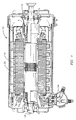
- FIG 1 shows a generator 10 comprising an axially extending rotor 12 enclosed in an annular stator 14 that surrounds and sleeves the rotor 12.
- the rotor 12 has a shaft 16 in which conductive coil windings 18 are axially arranged.
- the stator 14 has laminate punchings 20 that collectively form an annular core in which conductive coil windings 22 are positioned parallel with respect to the axial rotor coils 18.
- a DC electrical current is provided to the rotor coil windings 18.
- the rotating electrically charged rotor 12 creates a magnetic flux that induces an AC electrical current in the stationary stator coil windings 22.
- This induced AC electrical current is then drawn from stator leads 24 through one or more transformers and then to the power grid, and constitutes the electricity that the power generation plant provides to electricity consumers.
- the generator 10 has a frequency source signal (not shown in Figure 1) in operative association with the rotor 12 and stator 14 representative of an actual frequency at which the generator 10 is operating.
- the generator 10 also has a forcing source signal (not shown in Figure 1) in operative association with the rotor 12 and stator 14 representative of an actual forcing level at which the generator 10 is operating.
- the term "forcing" is defined herein as alternating torque applied to the rotor of the generator 10. Forcing is typically caused by negative sequence excitation, which causes unequal loads to be applied to generator windings and oscillating torques to be applied to the generator rotating components.
- a relay system (not shown in Figure 1) is adapted to respond to the frequency source signal and the forcing source signal by comparing the actual frequency with a predetermined desired frequency range and comparing the actual forcing level with at least one predetermined maximum forcing level.
- the relay system selectively trips the generator 10 to an off-line mode depending upon the comparisons.
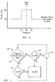
- Figure 2 shows a diagram of an exemplary standard negative-phase sequence current calculation curve. As shown, the negative-phase sequence current I 2 is a function of the three-phase currents Ia, Ib, Ic. One skilled in the art readily appreciates the relationship between negative-phase sequence current I 2 and negative sequence excitation, and that negative sequence excitation typically comprises the majority amount of alternating forces excitation and forcing.
- Negative sequence excitation typically causes a shaft torque proportional to the negative sequence current flow in the generator rotor and a corresponding torque at a frequency that is twice the system frequency (e.g., if the machine is operating synchronously with the system and the system frequency is 61 Hz and the negative sequence current flow in the stator windings is 5% of the machine capability, then an oscillating torque of roughly 5% of the steady-state torque, corresponding to a frequency of 122 Hz, is applied to the rotor.)
- generator frequency versus forcing is charted. As shown, the generator 10 can accept a maximum level of forcing depending upon the generator's operating frequency. In the exemplary chart, if the generator 10 is operating at less than 50 Hz it can accept up to 2% forcing; if the generator 10 is operating at 50-60 Hz it can accept up to 8% forcing; and if the generator 10 is operating at over 60 Hz it can accept up to 2% forcing.
- a relay can be used as a cutoff mechanism to ensure that the generator 10 does not receive or accept any forcing above the predetermined maximum levels.
- the frequency center line should typically be at about 50 or 60 Hz since that is the respective conventional nominal frequencies for Europe and the United States, although other convention-based frequencies can be used.
- the illustrated frequency range of the upper forcing level is 6 Hz (from 57 to 63 Hz), it could range from about 0-10 Hz or more depending upon the particular generator design and power grid.
- the illustrated maximum forcing range is 8% (from a low of 2% to a high of 10%), it can range from about 0-10% or more depending upon the particular generator design, power grid, and applicable standards.
- the illustrated lower maximum forcing level is 2%, it can range from 0-7% or more depending upon the particular generator design and power grid; similarly, although the illustrated upper forcing level is 8%, it can range from 0-10% or more.
- the geometry of the frequency versus forcing line need not be stepped, but can also be rounded, saw-toothed, curved, angular, linear, and combinations thereof to depict that the forcing limit can vary in a manner that is more gradual and/or complex than shown, as will be understood one skilled in the art.
- the particular configuration of the frequency versus forcing line can depend upon the particular generator design and power grid.
- Modern relays are typically programmable and multifunctional, so the relaying logic described herein can be programmed into a suitable generator protection module as will be understood by one skilled in the art, such as those commercially available from the Beckwith Electric Company, Inc. of Largo, Florida, such as Beckwith part number M-3425.
- the above-described linked relay system 26 can associate off-nominal frequency and alternating forces excitation and thereby provide several benefits, including superior generator protection and an increase in the allowable operating frequency range of synchronous generators 10 on a power grid.
- relay refers to the equipment used to protect and control the generator and that the functions described herein could be incorporated into control equipment, such as turbine controls, that are not normally described as relays or protective equipment but are capable of some protective functions and are sometimes used to provided similar functionality.
- a flow diagram shows use of the linked relay system 26 in a generator 10 for monitoring off-nominal frequency and alternating forces excitation.
- the linked relay system 28 is adapted to respond to the frequency source signal and the forcing source signal by comparing the actual frequency with a predetermined desired frequency range and comparing the actual forcing amount with at least one predetermined maximum forcing amount, and selectively tripping the generator 10 to an off-line mode depending upon these comparisons.
- the linked relay system 26 determines the off-nominal frequency. If the off-nominal frequency is within certain limits (e.g. IEC Zone A), then the linked relay system 26 determines if the forcing amount is below the upper forcing limit (e.g. less than 10%) for alternating forces excitation or forcing (Box 32). If the forcing amount is below the upper forcing limit, then the generator 10 is operating in a suitably safe mode and this process of monitoring the off-nominal frequency and alternating forces excitation is repeated as desired. If, however, the forcing is above the upper forcing limit, then the generator 10 is tripped to an off-line mode (Box 36).
- the upper forcing limit e.g. less than 10%
- the linked relay system 28 determines the off-nominal frequency. If the off-nominal frequency is outside certain limits (e.g. IEC Zone A), then the linked relay system 26 determines if the forcing amount is below the lower forcing limit (e.g. less than 2%) for alternating forces excitation or forcing (Box 34). If the forcing amount is below the lower forcing limit, then the generator 10 is operating in a suitably safe mode and this process of monitoring the off-nominal frequency and alternating forces excitation is repeated as desired. If, however, the forcing is above the lower forcing limit, then the generator 10 is tripped to an off-line mode (Box 36).
- the lower forcing limit e.g. less than 28%
- the linked relay system 28 need not follow the step sequence as shown in the exemplary flow diagram, but can also follow other step sequences, or include additional intermediate steps or a continuous variation in allowable forcing with frequency.
- the linked relay system 28 can first determine the forcing amount and then determine the off-nominal frequency using an algorithm that accounts for the characteristics of the machine and the local frequency requirements.
Landscapes
- Engineering & Computer Science (AREA)
- Power Engineering (AREA)
- Control Of Eletrric Generators (AREA)
- Protection Of Generators And Motors (AREA)
Applications Claiming Priority (2)
| Application Number | Priority Date | Filing Date | Title |
|---|---|---|---|
| US10/024,694 US6661207B2 (en) | 2001-12-17 | 2001-12-17 | Apparatus and method for protecting synchronous generators against off-nominal frequency deviation and alternating forces excitation |
| US24694 | 2001-12-17 |
Publications (3)
| Publication Number | Publication Date |
|---|---|
| EP1320165A2 true EP1320165A2 (fr) | 2003-06-18 |
| EP1320165A3 EP1320165A3 (fr) | 2006-04-12 |
| EP1320165B1 EP1320165B1 (fr) | 2012-12-26 |
Family
ID=21821904
Family Applications (1)
| Application Number | Title | Priority Date | Filing Date |
|---|---|---|---|
| EP02079811A Expired - Lifetime EP1320165B1 (fr) | 2001-12-17 | 2002-11-19 | Appareil et méthode de protection de générateurs synchrones de déviations de fréquence nominal et de forces d'excitation alternatives |
Country Status (2)
| Country | Link |
|---|---|
| US (1) | US6661207B2 (fr) |
| EP (1) | EP1320165B1 (fr) |
Families Citing this family (5)
| Publication number | Priority date | Publication date | Assignee | Title |
|---|---|---|---|---|
| US7372279B2 (en) * | 2005-05-27 | 2008-05-13 | Siemens Power Generation, Inc. | Power generation unit condition monitor using frequency profile analysis |
| US7877170B2 (en) * | 2007-05-24 | 2011-01-25 | Verdant Power | Remanent voltage generator tachometer and control for induction machine |
| EP2672596B1 (fr) | 2012-06-07 | 2020-08-05 | Grupo Guascor, S.L. Unipersonal | Unité de protection de générateur d'énergie |
| US9188632B1 (en) * | 2014-05-01 | 2015-11-17 | Siemens Energy, Inc. | Self learning radio frequency monitoring system for identifying and locating faults in electrical distribution systems |
| US10634807B2 (en) * | 2015-11-09 | 2020-04-28 | Halliburton Energy Services, Inc. | Determining borehole parameters using ultrasonic and micro-resistivity calipers |
Citations (1)
| Publication number | Priority date | Publication date | Assignee | Title |
|---|---|---|---|---|
| US3944846A (en) | 1974-03-19 | 1976-03-16 | Southern California Edison Company | Subsynchronous relay |
Family Cites Families (7)
| Publication number | Priority date | Publication date | Assignee | Title |
|---|---|---|---|---|
| AT399966B (de) * | 1993-03-19 | 1995-08-25 | Elin Energieversorgung | Synchronisiervorrichtung |
| US5541498A (en) * | 1994-12-08 | 1996-07-30 | Beckwith; Robert W. | Distribution circuit var management system using adaptive capacitor controls |
| DE69623692T2 (de) * | 1995-05-31 | 2003-05-22 | Kabushiki Kaisha Meidensha, Tokio/Tokyo | Verfahren und Vorrichtung zum Detektieren des Islanding-Betriebes eines verteilten Generators |
| US5805394A (en) * | 1997-06-17 | 1998-09-08 | Sundstrand Corporation | Overvoltage protection circuit for a generating system utilizing a fault current sensing Circuit in combination with a shunting circuit |
| DK174291B1 (da) * | 1997-06-26 | 2002-11-18 | Mita Teknik As | Fremgangsmåde til indkobling af en asynkron generator på et vekselspændingsnet, og en elektrisk kobling til brug ved denne fremgangsmåde |
| US6140803A (en) * | 1999-04-13 | 2000-10-31 | Siemens Westinghouse Power Corporation | Apparatus and method for synchronizing a synchronous condenser with a power generation system |
| SE517714C2 (sv) * | 2000-05-31 | 2002-07-09 | Abb Ab | Nätvärnssystem för skydd av ett totalt elkraftsystems integritet mot svagt dämpade effektsvängningar, elkraftsystem innefattande ett nätvärn, systemskyddssystemförfarande, systemskyddsterminal, datorprogramprodukt samt datorläsbart medium |
-
2001
- 2001-12-17 US US10/024,694 patent/US6661207B2/en not_active Expired - Lifetime
-
2002
- 2002-11-19 EP EP02079811A patent/EP1320165B1/fr not_active Expired - Lifetime
Patent Citations (1)
| Publication number | Priority date | Publication date | Assignee | Title |
|---|---|---|---|---|
| US3944846A (en) | 1974-03-19 | 1976-03-16 | Southern California Edison Company | Subsynchronous relay |
Also Published As
| Publication number | Publication date |
|---|---|
| EP1320165A3 (fr) | 2006-04-12 |
| US20030111981A1 (en) | 2003-06-19 |
| EP1320165B1 (fr) | 2012-12-26 |
| US6661207B2 (en) | 2003-12-09 |
Similar Documents
| Publication | Publication Date | Title |
|---|---|---|
| Nøland et al. | Excitation system technologies for wound-field synchronous machines: Survey of solutions and evolving trends | |
| JP5014437B2 (ja) | 励磁機と、送電系統に接続されない電力変換器とを有する可変速風力タービンのための電圧低下対応ライドスルーシステム | |
| US9548605B2 (en) | Protection circuits and methods for electrical machines | |
| US4384246A (en) | Series-thyristor subsynchronous damper for power generators | |
| Schaefer | Excitation control of the synchronous motor | |
| US6661207B2 (en) | Apparatus and method for protecting synchronous generators against off-nominal frequency deviation and alternating forces excitation | |
| Parsons | Cogeneration application of induction generators | |
| Clark et al. | Industrial and cogeneration protection problems requiring simulation | |
| de Oliveira Costa et al. | Electrical power quality and the challenges faced by power assemblies applications in petrochemical industry | |
| US20180102638A1 (en) | Fault current enhancement for energy resources with power electronic interface | |
| Baldwin et al. | Improve turbine-generator protection for increased plant reliability | |
| US20040212353A1 (en) | Use of a closing impedance to minimize the adverse impact of out-of-phase generator synchronization | |
| Parrish et al. | Synchronous versus induction motors: plant efficiency benefits resulting from the use of synchronous motors | |
| KR101664162B1 (ko) | 발전기 보호장치 및 보호방법 | |
| ASHRAF | SUPERVISED INDUSTRIAL TRAINING REPORT AT SHAH TAJ SUGAR INDUSTARIES | |
| Scharlach et al. | Lessons learned from generator event reports | |
| Akinwole | Improving industrial three phase induction motor availability using protection devices | |
| Singh et al. | Mitigation of switching effects on induction motor under star-delta scheme based energy conservation | |
| Muzzammel et al. | Simulation Analysis of Fully Protected Induction Motor | |
| Chay et al. | Impact of grid code evolution on the design of the generators for nuclear plants (Half speed, power above 800 MVA) | |
| Zimmerman et al. | Starting requirements and effects of large synchronous motors | |
| Fennell et al. | Sequential tripping of steam turbine generators: Working group report | |
| JPH05316800A (ja) | 同期発電機の過励磁防止制御装置 | |
| CN117833584A (zh) | 一种低转速大扭矩同步电机及其制做方法 | |
| Patterson et al. | Reclosing and tapped motor load |
Legal Events
| Date | Code | Title | Description |
|---|---|---|---|
| PUAI | Public reference made under article 153(3) epc to a published international application that has entered the european phase |
Free format text: ORIGINAL CODE: 0009012 |
|
| AK | Designated contracting states |
Designated state(s): AT BE BG CH CY CZ DE DK EE ES FI FR GB GR IE IT LI LU MC NL PT SE SK TR |
|
| AX | Request for extension of the european patent |
Extension state: AL LT LV MK RO SI |
|
| RAP1 | Party data changed (applicant data changed or rights of an application transferred) |
Owner name: SIEMENS POWER GENERATION, INC. |
|
| PUAL | Search report despatched |
Free format text: ORIGINAL CODE: 0009013 |
|
| AK | Designated contracting states |
Kind code of ref document: A3 Designated state(s): AT BE BG CH CY CZ DE DK EE ES FI FR GB GR IE IT LI LU MC NL PT SE SK TR |
|
| AX | Request for extension of the european patent |
Extension state: AL LT LV MK RO SI |
|
| 17P | Request for examination filed |
Effective date: 20060630 |
|
| AKX | Designation fees paid |
Designated state(s): DE FR GB IT |
|
| RAP1 | Party data changed (applicant data changed or rights of an application transferred) |
Owner name: SIEMENS ENERGY, INC. |
|
| 17Q | First examination report despatched |
Effective date: 20111117 |
|
| GRAP | Despatch of communication of intention to grant a patent |
Free format text: ORIGINAL CODE: EPIDOSNIGR1 |
|
| GRAS | Grant fee paid |
Free format text: ORIGINAL CODE: EPIDOSNIGR3 |
|
| GRAA | (expected) grant |
Free format text: ORIGINAL CODE: 0009210 |
|
| AK | Designated contracting states |
Kind code of ref document: B1 Designated state(s): DE FR GB IT |
|
| REG | Reference to a national code |
Ref country code: GB Ref legal event code: FG4D |
|
| REG | Reference to a national code |
Ref country code: DE Ref legal event code: R096 Ref document number: 60244273 Country of ref document: DE Effective date: 20130228 |
|
| PLBE | No opposition filed within time limit |
Free format text: ORIGINAL CODE: 0009261 |
|
| STAA | Information on the status of an ep patent application or granted ep patent |
Free format text: STATUS: NO OPPOSITION FILED WITHIN TIME LIMIT |
|
| 26N | No opposition filed |
Effective date: 20130927 |
|
| REG | Reference to a national code |
Ref country code: DE Ref legal event code: R097 Ref document number: 60244273 Country of ref document: DE Effective date: 20130927 |
|
| REG | Reference to a national code |
Ref country code: FR Ref legal event code: PLFP Year of fee payment: 14 |
|
| REG | Reference to a national code |
Ref country code: FR Ref legal event code: PLFP Year of fee payment: 15 |
|
| REG | Reference to a national code |
Ref country code: FR Ref legal event code: PLFP Year of fee payment: 16 |
|
| PGFP | Annual fee paid to national office [announced via postgrant information from national office to epo] |
Ref country code: IT Payment date: 20171128 Year of fee payment: 16 |
|
| PGFP | Annual fee paid to national office [announced via postgrant information from national office to epo] |
Ref country code: FR Payment date: 20181120 Year of fee payment: 17 Ref country code: GB Payment date: 20181106 Year of fee payment: 17 |
|
| PGFP | Annual fee paid to national office [announced via postgrant information from national office to epo] |
Ref country code: DE Payment date: 20190118 Year of fee payment: 17 |
|
| PG25 | Lapsed in a contracting state [announced via postgrant information from national office to epo] |
Ref country code: IT Free format text: LAPSE BECAUSE OF NON-PAYMENT OF DUE FEES Effective date: 20181119 |
|
| REG | Reference to a national code |
Ref country code: DE Ref legal event code: R119 Ref document number: 60244273 Country of ref document: DE |
|
| GBPC | Gb: european patent ceased through non-payment of renewal fee |
Effective date: 20191119 |
|
| PG25 | Lapsed in a contracting state [announced via postgrant information from national office to epo] |
Ref country code: FR Free format text: LAPSE BECAUSE OF NON-PAYMENT OF DUE FEES Effective date: 20191130 Ref country code: DE Free format text: LAPSE BECAUSE OF NON-PAYMENT OF DUE FEES Effective date: 20200603 Ref country code: GB Free format text: LAPSE BECAUSE OF NON-PAYMENT OF DUE FEES Effective date: 20191119 |