EP1320187A2 - Verfahren und System zur Regelung einer permanenterregten Maschine - Google Patents
Verfahren und System zur Regelung einer permanenterregten Maschine Download PDFInfo
- Publication number
- EP1320187A2 EP1320187A2 EP02079750A EP02079750A EP1320187A2 EP 1320187 A2 EP1320187 A2 EP 1320187A2 EP 02079750 A EP02079750 A EP 02079750A EP 02079750 A EP02079750 A EP 02079750A EP 1320187 A2 EP1320187 A2 EP 1320187A2
- Authority
- EP
- European Patent Office
- Prior art keywords
- sensor assembly
- rotor
- mode
- sector
- angular
- Prior art date
- Legal status (The legal status is an assumption and is not a legal conclusion. Google has not performed a legal analysis and makes no representation as to the accuracy of the status listed.)
- Withdrawn
Links
Images


Classifications
-
- H—ELECTRICITY
- H02—GENERATION; CONVERSION OR DISTRIBUTION OF ELECTRIC POWER
- H02P—CONTROL OR REGULATION OF ELECTRIC MOTORS, ELECTRIC GENERATORS OR DYNAMO-ELECTRIC CONVERTERS; CONTROLLING TRANSFORMERS, REACTORS OR CHOKE COILS
- H02P21/00—Arrangements or methods for the control of electric machines by vector control, e.g. by control of field orientation
- H02P21/06—Rotor flux based control involving the use of rotor position or rotor speed sensors
-
- H—ELECTRICITY
- H02—GENERATION; CONVERSION OR DISTRIBUTION OF ELECTRIC POWER
- H02P—CONTROL OR REGULATION OF ELECTRIC MOTORS, ELECTRIC GENERATORS OR DYNAMO-ELECTRIC CONVERTERS; CONTROLLING TRANSFORMERS, REACTORS OR CHOKE COILS
- H02P21/00—Arrangements or methods for the control of electric machines by vector control, e.g. by control of field orientation
- H02P21/34—Arrangements for starting
-
- H—ELECTRICITY
- H02—GENERATION; CONVERSION OR DISTRIBUTION OF ELECTRIC POWER
- H02P—CONTROL OR REGULATION OF ELECTRIC MOTORS, ELECTRIC GENERATORS OR DYNAMO-ELECTRIC CONVERTERS; CONTROLLING TRANSFORMERS, REACTORS OR CHOKE COILS
- H02P6/00—Arrangements for controlling synchronous motors or other dynamo-electric motors using electronic commutation dependent on the rotor position; Electronic commutators therefor
- H02P6/20—Arrangements for starting
Definitions
- the present invention is generally related to control of electromechanical machines, and, more particularly, the present invention is related to method and system for controlling a permanent magnet (PM) machine without using high resolution absolute rotor position information.
- PM permanent magnet
- the absolute position of the rotor of the machine is generally required to appropriately position the stator's current vector relative to the rotor's magnet flux vector in order for the machine to develop a desired level of torque.
- resolver devices can accurately determine the absolute position of the rotor, such devices generally require tight positional tolerances and associated driving circuitry, and thus their relatively high cost incrementally adds to the overall cost of a propulsion system that uses permanent magnet machines.
- sensorless techniques may require computationally intensive algorithms and may not be suitable to applications, such as those using flywheel alternator starter systems, where a relatively high initial torque is desired so that, for example, an internal combustion engine coupled to the starter system can be started as quickly as possible under extreme environmental conditions.
- absolute position sensors based on standard position-pulse techniques have limitations since such sensors may not be effectively utilized for applications that require high initial starting torque since the absolute position is not determined until a pulse indicative of relative position of the rotor is received by a controller. For example, the rotor position determination may not occur for up to about one mechanical revolution of the rotor, during which the controller would be unable to appropriately position the current vector relative to the flux vector. This condition could lead either to reduced torque generation or even to negative torque generation.
- the use of the expression brushless direct current mode of operation is a bit of a misnomer since the mode is not truly a DC mode, if by DC one means a mode whose machine voltages and currents are unidirectional for a given condition of speed and torque.
- the voltages and currents of the machine generally vary trapezoidally in the BLDC mode of operation, however, the expression BLDC as used herein is consistent with traditional and well-understood usage in the field of electrical motors.
- the present invention fulfills the foregoing needs by providing in one aspect thereof a method for controlling a permanent magnet machine.
- the method provides a sensor assembly for sensing rotor sector position relative to a plurality of angular sectors.
- the method allows starting the machine in a brushless direct current mode of operation using a calculated initial rotor position based on angular sector position information from the sensor assembly.
- the method Upon reaching a predefined mode-crossover criterion, the method allows switching to a sinusoidal mode of operation using rotor angle position based on extrapolating angular sector position information from the sensor assembly.
- the present invention further fulfills the foregoing needs by providing in another aspect thereof, a system for controlling a permanent magnet machine.
- the system includes a sensor assembly for sensing rotor sector position relative to a plurality of angular sectors.
- a rotor angle processor includes an angular sector assigner configured to assign rotor position based on angular sector position information from the sensor assembly, with an initial rotor position being used for starting the machine in a brushless direct current mode of operation.
- the rotor angle processor further includes an extrapolator configured to determine rotor angle position based on angular sector position information from the sensor assembly.
- a switching module is responsive to a switching signal from a mode-crossover controller to pass rotor position from the extrapolator.
- the rotor position information from the extrapolator is used to provide a sinusoidal mode of operation, in lieu of the brushless direct current mode of operation, upon the mode-crossover controller determining whether a predefined mode-crossover criterion has been reached.
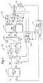
- FIG. 1 shows a block diagram representation of a system 10 embodying aspects of the present invention for controlling a permanent magnet machine (12).
- system 10 includes a sensor assembly 14 for sensing rotor sector position relative to a plurality of angular sectors.
- sensor assembly 14 comprises three sensors circumferentially spaced about 120 electrical degrees from one another. Examples of sensors that may be used for sensing rotor sector position include Hall-effect sensors, magneto-resistive sensors and optical sensors.
- the three sensors are electromagnetically coupled to a toothed wheel 16 with one tooth per pole pair.
- the rotor position would be known to a resolution of +/- 30 electrical degrees. That is, sensor assembly 14 allows determining the position of the rotor in any respective one of the six angular sectors. Since the machine is being started in a BLDC mode, it is desirable to assign the midpoint angle of the sector.
- One of the key features of the invention is the fact that a standard vector controller system is used during start up of the machine in a BLDC mode of operation.
- the inventors of the present invention have recognized that such standard vector controller may be, figuratively speaking,”forced” or “tricked” to operate during start up of the machine in the BLDC mode of operation and, thus, take advantage of the relatively superior starting torque generation afforded by that mode.
- the inventors of the present invention have further recognized that the transition from the BLDC mode to the sinusoidal mode of operation can be achieved in a seamless manner by the vector controller.
- the rotor sector position from sensor assembly 14 is supplied to a rotor angle processor 20 to determine the appropriate rotor position during the BLDC mode and during the sinusoidal mode.
- processor 20 includes an angular sector assigner 22 configured to assign rotor position ⁇ BLDC during the BLDC mode of operation based on the angular sector position information from sensor assembly 14.
- the rotor position ⁇ BLDC is passed through a mode-selector switch 25 to respective voltage and current transformation units 126 and 128 (FIG. 1) for starting the machine in the BLDC mode of operation.
- a sensor state determination module 24 is configured to determine the state of each sensor based on the state of the pulses from sensor assembly 14. Module 24 is further configured to determine, as the rotor of the machine rotates, the timing of each sensor state transition indicative of transitions between any two adjacent angular sectors.
- FIG. 4 in part illustrates exemplary sensor states corresponding to the angular sectors. For example, if the initial rotor position falls in a sector between zero and sixty degrees, then the initial rotor angle assignment in the BLDC mode may correspond to thirty degrees. As the rotor position transitions from that initial angular sector to the next angular sector, e.g., the angular sector between 60 and 120 degrees, then the next rotor angle assignment may correspond to ninety degrees.
- a mode crossover controller 26 Upon the machine reaching a predefined mode-crossover criterion, e.g., rotor machine speed, machine voltage limit, elapsed time value, rotor angle travel, etc, as determined by a mode crossover controller 26, the rotor angle position ⁇ EXT supplied to voltage and current transformation units 126 and 128 would be determined by a rotor angle and speed extrapolator 28 using extrapolation techniques well-understood by those skilled in the art.
- a mode-crossover criterion e.g., rotor machine speed, machine voltage limit, elapsed time value, rotor angle travel, etc.
- the present invention is not limited to the foregoing extrapolation equations since other extrapolation equations may be used for deriving rotor position information.
- the extrapolation equation may be based on parameters indicative of rotor acceleration, and may include a suitable digital filter to better accommodate rotor dynamics of any given machine application, and including sensor and target wheel variation.
- a module 32 processes the various sensor states so that in the event an invalid sensor state or invalid sensor sequence is determined, then a fault indication signal is generated so that appropriate corrective action may be taken.
- the extrapolated rotor position information is used by the voltage and current transformation units 126 and 128 to provide sinusoidal current mode of operation, in lieu of the BLDC mode of operation, upon the mode crossover controller 26 determining that the machine has reached the predefined mode crossover criterion.
- one or more parameters may be used to determine whether the machine has reached the mode crossover criterion, for example, rotor speed, machine voltage, elapsed time, rotor angle travel, etc.
- Each of the above parameters may be chosen as an indicator that the extrapolated rotor angle position has reached a sufficiently high level of accuracy to enable the machine to seamlessly transition from the BLDC mode of operation to the sinusoidal mode of operation.
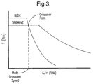
- FIG. 3 illustrates respective machine torque-speed plots for the BLDC and the sinusoidal modes of operations including an exemplary crossover point corresponding to a mode-crossover rotor speed.
- the direct (d) axis current reference (I ds ) and the quadrature (q) axis current reference (I qs ) may be adjusted as a function of commanded torque T e * and rotor speed ⁇ r using analytically and/or experimentally derived values stored in a look-up table 102 that may comprise a two-dimensional look-up table responsive to two respective inputs to supply two outputs.
- look-up table 102 may be configured to provide optimum efficiency control for an ideal case by adjusting the value of the d axis current reference (I ds ) and the q axis current reference (I qs ) as a function of commanded torque T e * and rotor speed ⁇ r .
- the value of the torque reference signal T e * may be externally-derived by a system master controller or may correspond to the torque value commanded by an operator through a suitable machine propulsion throttle handle.
- the d axis current reference, (I ds ) and a feedback current signal Id is each respectively applied to a subtractor 122 to generate a difference output signal.
- the subtracting operation respectively executed by subtractor 122 and other such devices described below may be executed by a summer having one inverting input terminal and one noninverting input terminal.
- any of the various arithmetic and logical operations performed in system 10 may be conducted through respective software modules as may be executed in a suitable microprocessor and such operations need not be executed through hardware modules.
- the difference output signal from subtractor 122 represents an error signal between the d axis current reference signal (Ids) and the feedback current signal Id.
- the torque-producing current component reference Iqs is processed by a subtractor 124 that receives a feedback current Iq.
- the difference output signal from subtractor 124 represents an error signal between the torque current component reference signal Iqs and the feedback current signal Iq.
- a standard vector controller may comprise components such as respective voltage and current transformation units 126 and 128, and two proportional plus integral (PI) current regulators 130 and 132, each such component using techniques well-understood by those skilled in the art.
- PI proportional plus integral
- Current transformation unit 128 converts the three-phase currents in the stationary frame into equivalent two-phase orthogonal currents in the rotor frame.
- the two orthogonal current signals I q and I d in the rotor frame are respectively applied to the two PI current regulators 130 and 132 as current feedback signals through subtractors 124 and 122.
- the output signals from the PI current regulators are then provided to voltage transformation unit 126 and are converted into equivalent two-phase voltage references in the stationary frame.
- Each respective output signal of voltage transformation unit 126 is then applied to a PWM inverter controller 140 that in one exemplary embodiment may comprise an over-modulation space vector PWM unit to generate six respective duty cycle values.
- the controller functionality is analogous to having six synchronous timers for respectively generating six-gate pulse signals to the respective gate drive circuits of an inverter 142 that energizes the phases of the permanent magnet machine 12.
- the inverter's legs will be appropriately switched on and off according to the voltage levels of the gate signals from the controller in order to control operation of the permanent magnet machine.
- FIG. 4 illustrates exemplary electromotive force (EMF) voltage signals for each phase of a three phase permanent magnet machine 12 (FIG. 1).
- EMF electromotive force
- FIG. 4 further illustrates signals 56, 58 and 60, such as may be generated by the sensor assembly 14 (FIG. 1), each representative of a respective stream of pulses indicative of rotor position relative to each phase of the machine.
- sensor assembly 14 comprises three sensors constructed to form an integrated sensor assembly. See U.S. Patent Application Serial No.
- FIG. 4 further illustrates exemplary phase currents 62, 64 and 66 that are produced by the machine when energized by an inverter circuit 142 (FIG. 1) in response to gating signals derived using combinatorial logic well-known to those skilled in the art for energizing the respective power switches in the inverter 142 based on the sensor state information.
- the present invention can be embodied in the form of computer-implemented processes and apparatus for practicing those processes.
- the present invention can also be embodied in the form of computer program code containing computer-readable instructions embodied in tangible media, such as floppy diskettes, CD-ROMs, hard drives, or any other computer-readable storage medium, wherein, when the computer program code is loaded into and executed by a computer, the computer becomes an apparatus for practicing the invention.
- the present invention can also be embodied in the form of computer program code, for example, whether stored in a storage medium, loaded into and/or executed by a computer, or transmitted over some transmission medium, such as over electrical wiring or cabling, through fiber optics, or via electromagnetic radiation, wherein, when the computer program code is loaded into and executed by a computer, the computer becomes an apparatus for practicing the invention.
- the computer program code segments configure the computer to create specific logic circuits or processing modules.
Landscapes
- Engineering & Computer Science (AREA)
- Power Engineering (AREA)
- Control Of Motors That Do Not Use Commutators (AREA)
Applications Claiming Priority (2)
| Application Number | Priority Date | Filing Date | Title |
|---|---|---|---|
| US7793 | 2001-12-03 | ||
| US10/007,793 US6774592B2 (en) | 2001-12-03 | 2001-12-03 | Method and system for controlling a permanent magnet machine |
Publications (2)
| Publication Number | Publication Date |
|---|---|
| EP1320187A2 true EP1320187A2 (de) | 2003-06-18 |
| EP1320187A3 EP1320187A3 (de) | 2004-04-07 |
Family
ID=21728169
Family Applications (1)
| Application Number | Title | Priority Date | Filing Date |
|---|---|---|---|
| EP02079750A Withdrawn EP1320187A3 (de) | 2001-12-03 | 2002-11-14 | Verfahren und System zur Regelung einer permanenterregten Maschine |
Country Status (2)
| Country | Link |
|---|---|
| US (1) | US6774592B2 (de) |
| EP (1) | EP1320187A3 (de) |
Cited By (5)
| Publication number | Priority date | Publication date | Assignee | Title |
|---|---|---|---|---|
| WO2009096649A1 (en) | 2008-01-31 | 2009-08-06 | Lg Electronics Inc. | Motor, apparatus for controlling motor, and method for starting motor |
| EP2605399A4 (de) * | 2011-10-17 | 2014-02-26 | Panasonic Corp | Motorantriebssystem und steuerungsverfahren dafür |
| EP2212991A4 (de) * | 2007-11-22 | 2016-11-30 | Lg Electronics Inc | Motor sowie vorrichtung und verfahren zur steuerung des motors |
| EP3557754A1 (de) * | 2018-04-17 | 2019-10-23 | Johnson Electric International AG | Motorantriebsschaltung, motorantriebsverfahren und motorvorrichtung mit verwendung davon |
| EP4287494A1 (de) * | 2022-06-02 | 2023-12-06 | Siemens Aktiengesellschaft | Bürstenlose gleichstrommaschine mit einer hall-sensoren umfassenden sensoreinrichtung |
Families Citing this family (16)
| Publication number | Priority date | Publication date | Assignee | Title |
|---|---|---|---|---|
| US20050263330A1 (en) * | 2004-05-28 | 2005-12-01 | Valeo Electrical Systems, Inc. | Field-oriented control for brushless DC motor |
| GB0415166D0 (en) * | 2004-07-06 | 2004-08-11 | Switched Reluctance Drives Ltd | Rotor position detection in an electrical machine |
| US20060066274A1 (en) * | 2004-09-30 | 2006-03-30 | Valeo Electrical Systems, Inc. | Overmodulation of electric motor in power steering system |
| US7075267B1 (en) * | 2004-12-29 | 2006-07-11 | Prolific Technology Inc. | Space vector-based current controlled PWM inverter for motor drives |
| GB0520178D0 (en) * | 2005-10-04 | 2005-11-09 | Switched Reluctance Drives Ltd | Rotor position detection in an electrical machine |
| US7282886B1 (en) * | 2006-08-04 | 2007-10-16 | Gm Global Technology Operations, Inc. | Method and system for controlling permanent magnet motor drive systems |
| CN101359892B (zh) * | 2007-08-03 | 2010-12-08 | 通用汽车环球科技运作公司 | 用于控制永磁电动机驱动系统的方法及系统 |
| TWI404324B (zh) * | 2008-05-15 | 2013-08-01 | Delta Electronics Inc | 馬達控制裝置及其控制方法 |
| US8264192B2 (en) * | 2009-08-10 | 2012-09-11 | Emerson Climate Technologies, Inc. | Controller and method for transitioning between control angles |
| KR101382305B1 (ko) * | 2010-12-06 | 2014-05-07 | 현대자동차주식회사 | 하이브리드 차량용 모터 제어 장치 |
| US9634593B2 (en) | 2012-04-26 | 2017-04-25 | Emerson Climate Technologies, Inc. | System and method for permanent magnet motor control |
| CN103470483B (zh) * | 2013-09-10 | 2016-01-06 | 广东美芝制冷设备有限公司 | 压缩机的控制方法及控制系统 |
| GB2566292B (en) * | 2017-09-07 | 2020-03-04 | Delphi Automotive Systems Lux | Method of controlling a brushless DC motor |
| TWI702782B (zh) * | 2017-10-26 | 2020-08-21 | 財團法人工業技術研究院 | 應用於三相直交流轉換器之電壓平衡控制方法及裝置 |
| US11588426B2 (en) * | 2020-01-17 | 2023-02-21 | Infineon Technologies Ag | Rotor angle error compensation for motors |
| CN114826039B (zh) * | 2022-03-01 | 2024-11-08 | 南京溧水电子研究所有限公司 | 适用于电动车电机的控制方法 |
Family Cites Families (17)
| Publication number | Priority date | Publication date | Assignee | Title |
|---|---|---|---|---|
| US3679954A (en) * | 1970-07-13 | 1972-07-25 | Lear Siegler Inc | Brushless d.c. motor with rate control of position sensor |
| JPS59123482A (ja) * | 1982-12-29 | 1984-07-17 | Fanuc Ltd | 同期モータの制御装置 |
| US4766359A (en) * | 1987-03-18 | 1988-08-23 | Westinghouse Electric Corp. | Absolute shaft position sensing circuit |
| JPH0349588A (ja) * | 1989-07-14 | 1991-03-04 | Omron Corp | 離散時間型acモータ制御装置 |
| JPH0670851A (ja) * | 1992-08-28 | 1994-03-15 | Toshiba Electric Appliance Co Ltd | 飲料供給装置における原料交換装置 |
| US5449986A (en) * | 1994-04-21 | 1995-09-12 | Dozor; David M. | Linearizing decoupling controller for electric motors |
| US5537020A (en) * | 1994-12-28 | 1996-07-16 | Hydro-Quebec | Method and apparatus for starting up a synchronous machine |
| US6081087A (en) * | 1997-10-27 | 2000-06-27 | Matsushita Electric Industrial Co., Ltd. | Motor control apparatus |
| US6075332A (en) * | 1998-05-14 | 2000-06-13 | Mccann; Roy A. | Predictive conductive angle motor control system for brake-by-wire application |
| JP3366858B2 (ja) * | 1998-05-29 | 2003-01-14 | 株式会社日立製作所 | 回転電機の制御装置 |
| US6605912B1 (en) | 1998-06-25 | 2003-08-12 | Delphi Technologies, Inc. | Method for controlling a permanent magnet motor |
| US6172498B1 (en) * | 1998-09-29 | 2001-01-09 | Rockwell Technologies, Llc | Method and apparatus for rotor angle detection |
| WO2001020767A1 (en) * | 1999-09-17 | 2001-03-22 | Delphi Technologies, Inc. | Low ripple permanent magnet motor control |
| US6324845B1 (en) | 2000-06-23 | 2001-12-04 | Delphi Technologies, Inc. | Self contained, supplemental vacuum assist unit for vehicle brake booster |
| GB0020501D0 (en) * | 2000-08-18 | 2000-10-11 | Switched Reluctance Drives Ltd | Apparatus and method for controlling an electric machine |
| US6407531B1 (en) * | 2001-01-09 | 2002-06-18 | Delphi Technologies, Inc. | Method and system for controlling a synchronous machine over full operating range |
| US6566830B2 (en) * | 2001-08-17 | 2003-05-20 | Delphi Technologies, Inc. | Method and system for controlling a permanent magnet machine |
-
2001
- 2001-12-03 US US10/007,793 patent/US6774592B2/en not_active Expired - Lifetime
-
2002
- 2002-11-14 EP EP02079750A patent/EP1320187A3/de not_active Withdrawn
Cited By (8)
| Publication number | Priority date | Publication date | Assignee | Title |
|---|---|---|---|---|
| EP2212991A4 (de) * | 2007-11-22 | 2016-11-30 | Lg Electronics Inc | Motor sowie vorrichtung und verfahren zur steuerung des motors |
| WO2009096649A1 (en) | 2008-01-31 | 2009-08-06 | Lg Electronics Inc. | Motor, apparatus for controlling motor, and method for starting motor |
| EP2238679A4 (de) * | 2008-01-31 | 2012-05-02 | Lg Electronics Inc | Motor, motorsteuerung und startverfahren für einen motor |
| US8384321B2 (en) | 2008-01-31 | 2013-02-26 | Lg Electronics Inc. | Motor, apparatus for controlling motor, and method for starting motor |
| EP2605399A4 (de) * | 2011-10-17 | 2014-02-26 | Panasonic Corp | Motorantriebssystem und steuerungsverfahren dafür |
| US8729846B2 (en) | 2011-10-17 | 2014-05-20 | Panasonic Corporation | Motor drive system and control method thereof |
| EP3557754A1 (de) * | 2018-04-17 | 2019-10-23 | Johnson Electric International AG | Motorantriebsschaltung, motorantriebsverfahren und motorvorrichtung mit verwendung davon |
| EP4287494A1 (de) * | 2022-06-02 | 2023-12-06 | Siemens Aktiengesellschaft | Bürstenlose gleichstrommaschine mit einer hall-sensoren umfassenden sensoreinrichtung |
Also Published As
| Publication number | Publication date |
|---|---|
| EP1320187A3 (de) | 2004-04-07 |
| US20030102829A1 (en) | 2003-06-05 |
| US6774592B2 (en) | 2004-08-10 |
Similar Documents
| Publication | Publication Date | Title |
|---|---|---|
| US6774592B2 (en) | Method and system for controlling a permanent magnet machine | |
| US6639371B2 (en) | Method and system for controlling start of a permanent magnet machine | |
| US6566830B2 (en) | Method and system for controlling a permanent magnet machine | |
| JP3636340B2 (ja) | 交流回転機用電力変換装置 | |
| Yoo et al. | Novel speed and rotor position estimation strategy using a dual observer for low-resolution position sensors | |
| JP3695342B2 (ja) | 電動機の制御装置 | |
| CN100407568C (zh) | 用于永磁体旋转电机的无传感器控制系统和方法 | |
| JP4483009B2 (ja) | モータ制御装置 | |
| US8754603B2 (en) | Methods, systems and apparatus for reducing power loss in an electric motor drive system | |
| JP4879649B2 (ja) | 電動機の制御装置 | |
| Scicluna et al. | Sensorless low/zero speed estimation for permanent magnet synchronous machine using a search-based real-time commissioning method | |
| JP2019103382A (ja) | モーター制御方法 | |
| JP2003299391A (ja) | 回転電機の制御装置 | |
| KR102331849B1 (ko) | Bldc 모터 제어장치 및 방법 | |
| JPH08308286A (ja) | 同期電動機の回転角速度検出装置、回転角度検出装置ならびに同期電動機の制御装置及び制御方法 | |
| JP4754378B2 (ja) | 電動機の制御装置 | |
| KR100713776B1 (ko) | 검출 전류의 비교를 통한 에스알엠의 여자 위치 검출 방법및 장치 | |
| JP4367279B2 (ja) | 同期モータの制御装置 | |
| US20220247335A1 (en) | Method for operating a brushless and sensorless multi-phase electric motor, and drive device with an electric motor | |
| JP2010226827A (ja) | モータ制御駆動装置及びモータ始動位置決め方法 | |
| JPH09215382A (ja) | 永久磁石同期モータの駆動方法 | |
| JP2019208329A (ja) | センサレスベクトル制御装置及びセンサレスベクトル制御方法 | |
| JP4400043B2 (ja) | 電動パワーステアリング装置 | |
| US12424952B2 (en) | Position sensing and control in a hybrid system | |
| Jayal et al. | Simplified sensor based vector control of permanent magnet synchronous motor drive |
Legal Events
| Date | Code | Title | Description |
|---|---|---|---|
| PUAI | Public reference made under article 153(3) epc to a published international application that has entered the european phase |
Free format text: ORIGINAL CODE: 0009012 |
|
| AK | Designated contracting states |
Designated state(s): AT BE BG CH CY CZ DE DK EE ES FI FR GB GR IE IT LI LU MC NL PT SE SK TR |
|
| AX | Request for extension of the european patent |
Extension state: AL LT LV MK RO SI |
|
| PUAL | Search report despatched |
Free format text: ORIGINAL CODE: 0009013 |
|
| AK | Designated contracting states |
Kind code of ref document: A3 Designated state(s): AT BE BG CH CY CZ DE DK EE ES FI FR GB GR IE IT LI LU MC NL PT SE SK TR |
|
| AX | Request for extension of the european patent |
Extension state: AL LT LV MK RO SI |
|
| AKX | Designation fees paid | ||
| REG | Reference to a national code |
Ref country code: DE Ref legal event code: 8566 |
|
| STAA | Information on the status of an ep patent application or granted ep patent |
Free format text: STATUS: THE APPLICATION IS DEEMED TO BE WITHDRAWN |
|
| 18D | Application deemed to be withdrawn |
Effective date: 20041008 |