EP1320209A2 - Disposifif de multiplexage de données numériques - Google Patents
Disposifif de multiplexage de données numériques Download PDFInfo
- Publication number
- EP1320209A2 EP1320209A2 EP02258509A EP02258509A EP1320209A2 EP 1320209 A2 EP1320209 A2 EP 1320209A2 EP 02258509 A EP02258509 A EP 02258509A EP 02258509 A EP02258509 A EP 02258509A EP 1320209 A2 EP1320209 A2 EP 1320209A2
- Authority
- EP
- European Patent Office
- Prior art keywords
- data
- digital data
- temporary memory
- occupied amount
- memory means
- Prior art date
- Legal status (The legal status is an assumption and is not a legal conclusion. Google has not performed a legal analysis and makes no representation as to the accuracy of the status listed.)
- Withdrawn
Links
Images



Classifications
-
- H—ELECTRICITY
- H04—ELECTRIC COMMUNICATION TECHNIQUE
- H04N—PICTORIAL COMMUNICATION, e.g. TELEVISION
- H04N7/00—Television systems
- H04N7/24—Systems for the transmission of television signals using pulse code modulation
- H04N7/52—Systems for transmission of a pulse code modulated video signal with one or more other pulse code modulated signals, e.g. an audio signal or a synchronizing signal
-
- H—ELECTRICITY
- H04—ELECTRIC COMMUNICATION TECHNIQUE
- H04J—MULTIPLEX COMMUNICATION
- H04J3/00—Time-division multiplex systems
- H04J3/16—Time-division multiplex systems in which the time allocation to individual channels within a transmission cycle is variable, e.g. to accommodate varying complexity of signals, to vary number of channels transmitted
- H04J3/1682—Allocation of channels according to the instantaneous demands of the users, e.g. concentrated multiplexers, statistical multiplexers
-
- H—ELECTRICITY
- H04—ELECTRIC COMMUNICATION TECHNIQUE
- H04J—MULTIPLEX COMMUNICATION
- H04J3/00—Time-division multiplex systems
- H04J3/24—Time-division multiplex systems in which the allocation is indicated by an address the different channels being transmitted sequentially
- H04J3/247—ATM or packet multiplexing
-
- H—ELECTRICITY
- H04—ELECTRIC COMMUNICATION TECHNIQUE
- H04L—TRANSMISSION OF DIGITAL INFORMATION, e.g. TELEGRAPHIC COMMUNICATION
- H04L47/00—Traffic control in data switching networks
- H04L47/10—Flow control; Congestion control
- H04L47/29—Flow control; Congestion control using a combination of thresholds
-
- H—ELECTRICITY
- H04—ELECTRIC COMMUNICATION TECHNIQUE
- H04L—TRANSMISSION OF DIGITAL INFORMATION, e.g. TELEGRAPHIC COMMUNICATION
- H04L47/00—Traffic control in data switching networks
- H04L47/10—Flow control; Congestion control
- H04L47/30—Flow control; Congestion control in combination with information about buffer occupancy at either end or at transit nodes
-
- H—ELECTRICITY
- H04—ELECTRIC COMMUNICATION TECHNIQUE
- H04L—TRANSMISSION OF DIGITAL INFORMATION, e.g. TELEGRAPHIC COMMUNICATION
- H04L47/00—Traffic control in data switching networks
- H04L47/50—Queue scheduling
-
- H—ELECTRICITY
- H04—ELECTRIC COMMUNICATION TECHNIQUE
- H04L—TRANSMISSION OF DIGITAL INFORMATION, e.g. TELEGRAPHIC COMMUNICATION
- H04L49/00—Packet switching elements
- H04L49/90—Buffering arrangements
-
- H—ELECTRICITY
- H04—ELECTRIC COMMUNICATION TECHNIQUE
- H04N—PICTORIAL COMMUNICATION, e.g. TELEVISION
- H04N21/00—Selective content distribution, e.g. interactive television or video on demand [VOD]
- H04N21/20—Servers specifically adapted for the distribution of content, e.g. VOD servers; Operations thereof
- H04N21/23—Processing of content or additional data; Elementary server operations; Server middleware
- H04N21/234—Processing of video elementary streams, e.g. splicing of video streams or manipulating encoded video stream scene graphs
- H04N21/23406—Processing of video elementary streams, e.g. splicing of video streams or manipulating encoded video stream scene graphs involving management of server-side video buffer
-
- H—ELECTRICITY
- H04—ELECTRIC COMMUNICATION TECHNIQUE
- H04N—PICTORIAL COMMUNICATION, e.g. TELEVISION
- H04N21/00—Selective content distribution, e.g. interactive television or video on demand [VOD]
- H04N21/20—Servers specifically adapted for the distribution of content, e.g. VOD servers; Operations thereof
- H04N21/23—Processing of content or additional data; Elementary server operations; Server middleware
- H04N21/236—Assembling of a multiplex stream, e.g. transport stream, by combining a video stream with other content or additional data, e.g. inserting a URL [Uniform Resource Locator] into a video stream, multiplexing software data into a video stream; Remultiplexing of multiplex streams; Insertion of stuffing bits into the multiplex stream, e.g. to obtain a constant bit-rate; Assembling of a packetised elementary stream
- H04N21/2365—Multiplexing of several video streams
-
- H—ELECTRICITY
- H04—ELECTRIC COMMUNICATION TECHNIQUE
- H04N—PICTORIAL COMMUNICATION, e.g. TELEVISION
- H04N21/00—Selective content distribution, e.g. interactive television or video on demand [VOD]
- H04N21/20—Servers specifically adapted for the distribution of content, e.g. VOD servers; Operations thereof
- H04N21/23—Processing of content or additional data; Elementary server operations; Server middleware
- H04N21/236—Assembling of a multiplex stream, e.g. transport stream, by combining a video stream with other content or additional data, e.g. inserting a URL [Uniform Resource Locator] into a video stream, multiplexing software data into a video stream; Remultiplexing of multiplex streams; Insertion of stuffing bits into the multiplex stream, e.g. to obtain a constant bit-rate; Assembling of a packetised elementary stream
- H04N21/2368—Multiplexing of audio and video streams
-
- H—ELECTRICITY
- H04—ELECTRIC COMMUNICATION TECHNIQUE
- H04N—PICTORIAL COMMUNICATION, e.g. TELEVISION
- H04N21/00—Selective content distribution, e.g. interactive television or video on demand [VOD]
- H04N21/40—Client devices specifically adapted for the reception of or interaction with content, e.g. set-top-box [STB]; Operations thereof
- H04N21/43—Processing of content or additional data, e.g. demultiplexing additional data from a digital video stream; Elementary client operations, e.g. monitoring of home network or synchronising decoder's clock; Client middleware
- H04N21/44—Processing of video elementary streams, e.g. splicing a video clip retrieved from local storage with an incoming video stream or rendering scenes according to encoded video stream scene graphs
- H04N21/44004—Processing of video elementary streams, e.g. splicing a video clip retrieved from local storage with an incoming video stream or rendering scenes according to encoded video stream scene graphs involving video buffer management, e.g. video decoder buffer or video display buffer
Definitions
- the present invention relates to a digital data multiplexing apparatus and, in particular, to a digital data multiplexing apparatus that inputs a plurality of kinds of digital data, for example, various kinds of packet data including videos, voices and text data, multiplexes the data in a mixed state and outputs the multiplexed data.
- a digital data multiplexing apparatus that inputs a plurality of kinds of digital data, for example, various kinds of packet data including videos, voices and text data, multiplexes the data in a mixed state and outputs the multiplexed data.
- such digital data is input to digital data multiplexing apparatus as various kinds of packet data, and multiplexed in a mixed state of the data to be sent and received.
- the digital data multiplexing apparatus for multiplexing digital data uses a plurality of temporary memory means (buffer memory) for temporarily storing a plurality of kinds of digital data in order to match input timing of the digital data.
- buffer memory temporary memory means
- This conventional digital data multiplexing apparatus is disclosed, for example, in Japanese Patent Laid-Open No. 9-205407.
- a multiplexing technique described in such a patent application selects digital data temporality stored in a pertinent buffer memory as temporary memory means, thereby making it possible to select data surely and control a size (memory capacity) of a buffer memory to be necessary minimum.
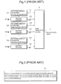
- Fig. 1 is a block diagram of a digital data multiplexing apparatus for explaining a conventional example.
- Fig.2 shows a program for explaining a buffer selecting operation of a data selection device shown in Fig. 1.
- the conventional digital data multiplexing apparatus is provided with: a plurality of buffer memories B1 to Bn for inputting digital data A1 to An from input terminals, respectively, and storing the digital data temporarily; occupied amount of buffer calculation devices O1 to On for calculating occupied state of data capacity in a plurality of buffer memories B1 to Bn; and a data selection device 6 for selecting output digital data C1 to Cn of the buffer memories B1 to Bn based on multiplex control signals 5-1 to 5-n, which are outputted from the occupied amount of buffer calculation devices O1 to On, respectively, and represent an input state of the buffer memories, and outputting the digital data as multiplexed data 7.
- digital data is selected as described in a selection program 11a shown in Fig. 2.
- digital data A1 to An are written in the buffer memories B1 to Bn, respectively.
- the occupied amount of buffer calculation devices O1 to On calculate an occupied amount of data in the buffer memories B1 to Bn, respectively.
- a threshold value is set in the occupied amount of buffer calculation devices O1 to On, respectively. If a calculated occupied amount of buffer has exceeded the threshold value, the occupied amount of buffer calculation devices O1 to On send the multiplex control signals 5-1 to 5-n indicating the state to the data selection device 6.
- the data selection device 6 sequentially reads out data from the buffer memories B1 to Bn in which the occupied amount of buffer has exceeded the threshold value and outputs the multiplexed data 7 of a fixed rate.
- the buffer memories B1 to Bn are selected in accordance with a priority. However, unselected ones of the buffer memories B1 to Bn are kept waited until outputs from selected ones of the buffer memories B1 to Bn end.
- a buffer memory for a second channel requires an extra buffer memory for being kept waited until an output from a buffer memory for a first channel ends.
- a buffer memory to be selected third requires an extra buffer memory for being kept waited until an output from a buffer memory selected first ends and an output from a buffer memory selected second ends. Therefore, as the number of input channels increases, a capacity necessary for a buffer memory selected last also increases.
- the above-described conventional digital data multiplexing apparatus has a drawback in that, as the number of channels of digital data to be input increases, a capacity of a buffer memory necessary for a channel with a low priority also increases.
- the invention seeks to provide for digital data multiplexing apparatus having advantages over known such apparatus.
- a plurality of temporary memory means for temporarily storing digital data individually; a plurality of occupied amount of data calculation means for calculating occupied amounts of digital data of the plurality of temporary memory means, respectively; occupied amount comparison means for comparing a result of calculation of the plurality of occupied amount of data calculation means and a threshold value of an occupied amount set for respective temporary memory means in advance; and data selection means for selecting an output from the plurality of temporary memory means to multiplex the output by a unit of packet according to a result of comparison of the occupied amount comparison means.
- the present invention advantageously provides a digital data multiplexing apparatus that can reduce a size, i.e. capacity, of an input buffer memory in multiplexing digital data by a unit of packet and outputting the data.
- the digital data multiplexing apparatus of the present invention can adopt various forms of application as described below.
- the data selection means of the digital data multiplexing apparatus of the present invention can select digital data stored in the pertinent temporary memory means.
- the data selection means can select digital data stored in a temporary memory means having a largest occupied amount among the plurality of temporary memory means.
- the plurality of temporary memory means of the digital data multiplexing apparatus of the present invention can use a buffer memory, respectively.
- the plurality of occupied amount of data calculation means use an occupied amount of buffer calculation device, respectively.
- a plurality of temporary memory means for temporarily storing digital data individually; a plurality of occupied amount of data calculation means for calculating occupied amounts of digital data of the plurality of temporary memory means, respectively; a priority control device that is connected to at least one out of the plurality of occupied amount of data calculation means and changes a priority of a pertinent temporary memory means among the plurality of temporary memory means; occupied amount comparison means for comparing an output from the priority control device and outputs from at least one of occupied amount of data calculation means not connected to the priority control device and a threshold value of an occupied amount to be set for respective temporary memory means in advance; and data selection means for selecting outputs from the plurality of temporary memory means according to a result of comparison of the occupied amount comparison means and multiplexing the outputs by a unit of packet.
- a plurality of temporary memory means for temporarily storing digital data individually; a plurality of occupied amount of data calculation means for calculating occupied amounts of digital data of the plurality of temporary memory means, respectively; a priority control device which is connected to at least one of the plurality of occupied amount of data calculation means and changes a priority of a pertinent temporary memory means among the plurality of temporary memory means; a priority selection switch which is connected to at least one of the plurality of occupied amount of data calculation means and the priority control device and switches an occupied amount of digital data of the temporary memory means outputted from the connected occupied amount of data calculation means and an occupied amount of digital data outputted from the connected priority control device; occupied amount comparison means for comparing an output from the priority control device and outputs from at least one of occupied amount of data calculation means not connected to the priority control device and a threshold value of an occupied amount to be set for respective temporary memory means in advance; and data selection means for selecting outputs from the plurality of temporary memory means according to
- a plurality of timing control devices for controlling timing for inputting and outputting digital data individually; one temporary memory means for inputting outputs from the plurality of timing control devices to temporarily store the outputs; occupied amount of data calculation means for calculating an occupied amount of digital data of the one temporary memory means for respective timing and generating a multiplex control signal corresponding to a plurality of kinds of digital data; occupied amount comparison means which is connected to the occupied amount of data calculation means and compares the multiplex control signal and a threshold value of an occupied amount of data to be set for respective timing control devices in advance; and data selection means for selecting an output from the one temporary memory means according to the multiplex control signal outputted from the occupied amount of data calculation means and a result of comparison of the occupied amount of comparison means and multiplexing the output by a unit of packet.
- an embodiment of the present invention relates to a digital data multiplexing apparatus for outputting data by a unit of packet, wherein the digital data multiplexing apparatus calculates an occupied amount of input buffers of a plurality of channels, compares the occupied amount with a threshold value set in advance and selects a buffer of which an occupied amount is the largest out of buffers of which the occupied amount has exceeded the threshold value and outputs the data, thereby reducing a size of the buffer.
- the conventional digital data multiplexing apparatus will be described.
- the number of channels is three
- an output rate is 300 bytes/S
- a packet size is 100 bytes
- a threshold value is 100 bytes for each channel.
- an input rate of the A1 channel is 99 bytes/S
- an input rate of an A2 channel is 0.9 byte/S
- an input rate of an A3 channel is 0.1 byte/S.
- a state in which an A2 channel and an A3 channel have exceeded the threshold value immediately before an A1 channel exceeds the threshold value is assumed to be a state S20. Operations of the digital data multiplexing apparatus will be described from this state.
- This state (S20) occurs when input starting timing of each channel is staggered.
- the A2 channel is selected first in accordance with a priority set in advance. Thereafter, data for one packet is outputted via a data selection device.
- a state after the output is assumed to be a state S21.
- the A1 channel has an occupied amount for 1.98 packets
- the A2 channel has an occupied amount for 0.009 packet
- the A3 channel has an occupied amount for 1.001 packets.
- the A1 channel is selected in accordance with the priority.
- the A1 channel has the highest priority and is selected most preferentially whenever it exceeds the threshold value. That is, the A1 channel is in the worst case in the state S21 and requires a buffer memory capacity for approximately two packets.
- an input rate of the A2 channel is 99 bytes/S
- an input rate of the A1 channel is 0.9 byte/S
- an input rate of the A3 channel is 0.1 byte/S.
- a state in which the A3 channel has exceeded the threshold value immediately before the A1 channel and the A2 channel exceed the threshold value is assumed to be a state S31. Operations of the digital data multiplexing apparatus will be described from this state.
- This state (S31) also occurs when input starting timing of each channel is staggered as in the above-described operations. In such a state, since the A3 channel has exceeded the threshold value, the A3 channel is selected.
- a state after the output is assumed to be a state S32.
- the A1 channel has an occupied amount for 1.009 packets
- the A2 channel has an occupied amount for 1.998 packets
- the A3 channel has an occupied amount for 0.001 packet.
- the A1 channel is selected in accordance with the priority.
- a state after the A1 channel is outputted is assumed to be a state S33.
- the A1 channel has an occupied amount for 0.018 packet
- the A2 channel has an occupied amount for 2.988 packets
- the A3 channel has an occupied amount for 0.002 packet.
- the state at this point is the worst case of the A2 channel, and the A2 channel requires a buffer memory capacity for approximately three packets.
- the digital data multiplexing apparatus starts operation in a state in which a channel with a lower priority than the channel has exceeded the threshold value and a channel that is in a state immediately before the channel and a channel with a higher priority than the channel exceed the threshold value.
- the digital data multiplexing apparatus requires an extra buffer memory for weights for transfer for one channel that has exceeded the threshold value and transfer for the channel with a higher threshold value than the channel.
- a buffer memory for approximately one packet that is required immediately before the channel exceeds the threshold value and approximately two packets that are required for weights for two channels with a higher priority than the channel, the total three packets, is required (there is no channel with a lower priority than the channel) .
- a capacity of a buffer memory necessary for a channel with a lower priority than the channel increases.
- Fig. 3 is a block diagram of a digital data multiplexing apparatus for explaining a first embodiment of the present invention.
- the digital data multiplexing apparatus in multiplexing a plurality of kinds of digital data (channels) A1 to An, the digital data multiplexing apparatus is provided with: a plurality of buffer memories B1 to Bn as temporary memory means for temporarily storing the digital data A1 to An individually; a plurality of occupied amount of buffer calculation devices O1 to On (occupied amount of data calculation means) for calculating occupied amount of digital data of these buffer memories B1 to Bn, respectively; an occupied amount of buffer comparison device 9 for comparing occupied amount of buffer signals 8-1 to 8-n that are results of calculation of these plurality of occupied amount of buffer calculation devices O1 to On and a threshold value of an occupied amount to be set for respective buffer memories B1 to Bn in advance; and a data selection device 6 for selecting output digital data C1 to Cn of the buffer memories B1 to Bn according to results of comparison of occupied amounts 10-1 to
- the occupied amount of buffer calculation devices O1 to On calculate occupied amounts of data of the buffer memories B1 to Bn and output the occupied amount of buffer signals 8-1 to 8-n to the occupied amount of buffer comparison device 9 and, at the same time, output the multiplex control signals 5-1 to 5-n to the data selection device 6. That is, the occupied amount of buffer calculation devices O1 to On compare the occupied amounts of data with a threshold value set in advance and notify the data selection device 6 to the effect that the occupied amounts of data have exceeded the threshold value. In addition, the occupied amount of buffer comparison device 9 compares occupied amounts of buffer to find which occupied amount of buffer is the largest and outputs a result of the comparison to the data selection device 6. This data selection device 6 selects a buffer memory with the largest occupied amount of buffer out of the buffer memories B1 to Bn of which the occupied amount of buffer has exceeded the threshold value and outputs it as multiplexed data 7.
- the data selection device 6 selects digital data stored in the pertinent buffer memory.
- the data selection device 6 selects digital data stored in a buffer memory having a largest occupied amount among them. Therefore, the buffer memories B1 to Bn can reduce a necessary total data capacity.
- the digital data multiplexing apparatus of the present invention shown in Fig. 3 has the buffer memories B1 to Bn and the occupied amount of buffer calculation devices O1 to On for respective input channel data A1 to An.
- the occupied amount of buffer comparison device 9 commonly provided for the buffer memories and the occupied amount of buffer calculation devices monitors the input digital data A1 to An and the output digital data C1 to Cn, calculates an occupied amount of buffer, and outputs the occupied amounts of buffer 8-1 to 8-n.
- the occupied amount of buffer comparison device 9 compares the occupied amount of buffer and the threshold value set in advance and outputs the multiplex control signals 5-1 to 5-n.
- the occupied amount of buffer comparison device 9 compares the occupied amounts of buffer 8-1 to 8-n to identify an occupied amount of which buffer memory is the largest and, then, outputs a result of the comparison to the data selection device 6.
- the data selection device 6 inputs the multiplex control signals 5-1 to 5-n, selects a buffer memory having a largest occupied amount out of the buffer memories of which the occupied amount has exceeded the threshold value, and outputs the multiplexed output 7.
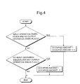
- Fig. 4 is a flow diagram of operations for increasing and decreasing an occupied amount of buffer in the occupied amount of buffer calculation device shown in Fig. 3.
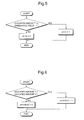
- Fig. 5 is a flow diagram of operations for judging an occupied amount of buffer in the occupied amount of buffer calculation device shown in Fig. 3.
- the occupied amount of buffer calculation device is constituted by, for example, an up-down counter.
- the up-down counter counts +1 when only an input operation takes place and counts -1 when only an output operation takes place.
- This value is an occupied amount of buffer.
- the occupied amount of buffer calculation device compares an occupied amount of buffer and a threshold value set in advance.
- the occupied amount of buffer calculation device outputs 1 if the occupied amount of buffer is larger, and outputs 0 if the occupied amount of buffer is smaller.
- This threshold value set in advance can be realized by, for example, referring to a value of a resistor.
- Fig. 6 is a flow diagram of operations for comparing an occupied amount of buffer in an occupied amount of buffer comparison device shown in Fig. 3.
- this occupied amount of buffer comparison device represents a case in which only two occupied amounts of buffer are compared and a result of the comparison is outputted.
- the same flow chart exists in all combinations of occupied amounts of buffer.
- the occupied amount of buffer comparison device determines that an occupied amount with a higher priority is larger and outputs the data.
- the occupied amount of buffer comparison device determines that the second occupied amount has a higher priority.
- Fig. 7 shows a program for explaining operations for selecting a buffer of a buffer selection unit provided inside a data selection device shown in Fig. 3.
- this data selection device for example, operation procedures of a buffer selection unit provided inside it are written as a program 11, and a buffer memory having a largest occupied amount is selected out of buffer memories selected according to a selection signal of each buffer memory.
- the number of channels of digital data to be inputted is three
- an output rate is 300 bytes/S
- a packet size is 100 bytes
- a threshold value for each channel is 100 bytes.
- a ratio of an input rate of each digital data may be any ratio as long as a sum of the input rates is equal to or lower than the output rate.
- the threshold value is preferably small. This is because a buffer memory is not selected unless an occupied amount of buffer exceeds the threshold value.
- the threshold value of each buffer it is necessary to set a smallest packet size. This is because, if a buffer memory smaller than the packet size is selected, it is possible that data output for one packet cannot be performed.
- the threshold value of each buffer the above-described packet size of 100 bytes is set.
- digital data is inputted in each buffer memory at the input rate of 100 bytes/S. Any buffer memory is not selected until an occupied amount of each buffer memory exceeds a threshold value of 100 bytes.
- the occupied amount of each buffer memory reaches 100 bytes.
- a selection signal becomes active for each channel simultaneously and outputted from each of the occupied amount calculation devices O1 to On.
- an occupied amount of buffer of the same 100 bytes is outputted for each channel. This state is assumed to be a state S1.
- an output buffer is selected from a result of comparison outputted from the occupied amount of buffer comparison device 9.
- the A3 channel is selected and outputted in accordance with a priority.
- a state in which this C channel is completed to be outputted for one packet one second later is assumed to be a state S2.
- the A1 channel and the A2 channel have occupied amounts for approximately 1.3 packets, and the A3 channel has an occupied amount for approximately 0.3 packet.
- the A1 channel has an occupied amount for approximately 1.7 packets, and the A2 channel and the A3 channel have occupied amounts for approximately 0.7 packet. Thereafter, what is selected next is the A1 channel that has exceeded the threshold value. A state after this A1 channel is outputted is the same as the state S1. These operations are repeated thereafter. Amaximum buffer memory necessary at this point is approximately 1.7 packets for the A1 channel.
- a worst case of the A1 channel is a case in which an input rate of the A1 channel is the highest.
- This input rate of the A1 channel is assumed to be 99 bytes/S that is a value close to 100 bytes/S.
- an input rate of the A2 channel is assumed to be 0.9 byte/S and an input rate of the A3 channel is assumed to be 0.1 byte/S.
- a sum of these input rates is 100 bytes/S.
- the aforementioned state S1 is an initial state of a worst case. This is because this state is a state with a largest occupied amount of buffer memory among the states before starting output of multiplexed data. This state occurs by staggering the start of input of each data in the order of the A3 channel, the A2 channel and the A1 channel.
- Combinations of states at an instance when a channel exceeds the threshold value and immediately before a channel exceeds the threshold value are close to the state S1 that is the initial state of the worst case without limit.
- the worst case of the A1 channel is the state S1 because there is a priority precisely.
- the worst case starts from a state in which the A1 channel is immediately before exceeding the threshold value and the A2 and A3 channels have exceeded the threshold value.
- This state is assumed to be a state S10.
- occupied amounts of both the channels are compared.
- the A3 channel having a higher priority is selected. At this point, the same channel is selected even if the A2 channel is immediately before exceeding the threshold value.
- a state in which this A3 channel is completed to be outputted for one packet one second after is assumed to be a state S11.
- the A1 channel has an occupied amount for 1.99 packets
- the A2 channel has an occupied amount for 1.009 packets
- the A3 channel has an occupied amount for 0.001 packet.
- the A1 channel having a larger occupied amount among the A1 channel and the A2 channel that have exceeded the threshold value.
- This state in which the A1 channel is completed to be outputted for one packet is assumed to be a state S12.
- the A1 channel has an occupied amount for 1.98 packets
- the A2 channel has an occupied amount for 1.018 packets
- the A3 channel has an occupied amount for 0.002 packet.
- the A1 channel hardly decreases because an input rate of the A1 channel is close to its output rate.
- the occupied amount decreases only one byte in one second. What is selected next is the A1 channel. This state in which the A1 channel is selected continues for a period during which the occupied amount of the A1 channel is more than that of the A2 channel.
- An occupied amount of each buffer memory at the time when the occupied amount of the A2 channel has exceeded the occupied amount of the A1 channel is as described below.
- the occupied amount of the A1 channel decreases one byte in one second, the occupied amount of the A2 channel increases by 0.9 byte.
- a condition of 1.9 - 0.01 x n ⁇ 1.018 + 0.009 x n is satisfied when n is 51, that is, 51 seconds after the state S12.
- the A1 channel has an occupied amount for 1.47 packets
- the A2 channel has an occupied amount for 1.477 packets
- the A3 channel has an occupied amount for 0.053 packet.
- This state is assumed to be a state S13. What is selected next is the A2 channel.
- the A1 channel has an occupied amount for 2.46 packets
- the A2 channel has an occupied amount for 0.486 packet
- the A3 channel has an occupied amount for 0.054 packet.
- an occupied amount of the A1 channel is for 2.46 packets .
- an input rate of the A1 channel is brought close to 100 bytes/S, which is its output rate, without limit, the occupied amount approaches 2.5 packets.
- the occupied amount of 2.5 packets is the peak amount. This can be proved by the following theory:
- an occupied amount of the A2 channel has a maximum value when an input rate of the A2 channel is the highest. If the maximum value is found in the same manner as in the A1 channel, the maximum value of the occupied amount is 2.5 packets. In addition, the same is true for the A3 channel.
- Fig. 8 is a block diagram of a digital data multiplexing apparatus for explaining a second embodiment of the present invention.
- Fig. 9 is a flow diagram of operations for controlling a priority of a buffer in a priority control device shown in Fig. 8.
- a priority control device 12 is additionally provided between the occupied amount of buffer calculation device O1 and the occupied amount of buffer comparison device 9 of the first embodiment.
- this priority control device 12 is provided with a function for, if an actual occupied amount of data of the buffer memory B1 has exceeded a threshold value, changing an occupied amount of buffer to a maximum value and outputting the data.
- the digital data multiplexing apparatus of the second embodiment of the present invention is capable of outputting data of a channel most preferentially if an occupied amount of the channel has exceeded the threshold value even if the occupied amount is smaller than those of other channels.
- the digital data multiplexing apparatus displays effects when it is desired to give a high priority to, for example, system data.
- the digital data multiplexing apparatus corresponds to one buffer memory B1, it is also possible to provide a plurality of buffer memories.
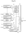
- Fig. 10 is a block diagram of a digital data multiplexing apparatus for explaining a third embodiment of the present invention.
- a priority selection switch 13 is additionally provided between the priority control device 12 and the occupied amount of buffer comparison device 9 of the second embodiment.
- This priority selection switch 13 is characterized by switching an occupied amount of buffer 8-1 outputted from the occupied amount of buffer calculation device O1 and an occupied amount of buffer outputted from the priority control device 12 according to a value of a resistor to output the data to the occupied amount of buffer comparison device 9. That is, in this case, the digital data multiplexing apparatus of the third embodiment of the present invention makes it possible to select whether a priority is raised or usual control is performed according to a type of digital data A1 to An to be inputted.
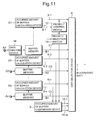
- Fig. 11 is a block diagram of a digital data multiplexing apparatus for explaining a fourth embodiment of the present invention.
- a data analysis device 14 is additionally provided in a pre-stage of the buffer memories B1 to Bn of the third embodiment. For example, when an input is a transport stream, this data analysis device 14 analyzes header information and, if the input is system data, controls the priority selection switch 13 according to the selection signal 12 for raising a priority.
- a digital data multiplexing apparatus of the fourth embodiment of the present invention makes it possible to automatically raise a priority if data is inputted of which a priority is required to be raised.
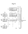
- Fig. 12 is a block diagram of a digital data multiplexing apparatus for explaining a fifth embodiment of the present invention.
- timing control devices 15A to 15N are additionally provided between the input digital data A1 to An and the buffer memory B of the first embodiment, one buffer memory B is shared by channels as a buffer memory necessary for the channels.
- output timing b1 to bn of data is adjusted in order to use the buffer memory B in a time division manner.
- the buffer memory operates at a clock three times as fast, and outputs data at first timing in the timing control device 15A for A1, at second timing in the timing control device 15B for A2 and at third timing in the timing control device 15N for A3 and repeatedly outputs the data in this way. Further, in this case, since the buffer memory B is shared and used in a time division manner, it is sufficient for the data selection device 6 to sequentially apply control indicated by dotted lines 120 to the buffer memory B.
- pointer management of the buffer memory B can be realized by changing a start address of each buffer memory.
- a size of a buffer memory necessary for one input is 2.5 packets. Therefore, for example, in a case in which one packet is 100 bytes, although a start address of A1 is 0, it is sufficient that a start address of A2 is 250 and a start address of A3 is 500.
- the digital data multiplexing apparatus of the present invention has an effect that a buffer memory capacity can be reduced by multiplexing to output data having a large occupied amount in a buffer memory.
- the digital data multiplexing apparatus of the present invention since a maximum value of a buffer memory necessary for each input channel does not change even if the number of input channels increases, the digital data multiplexing apparatus of the present invention has an effect in that the more the number of input channels increases, the more a sum of capacities necessary for a buffer memory can be reduced than in the past.
Landscapes
- Engineering & Computer Science (AREA)
- Signal Processing (AREA)
- Computer Networks & Wireless Communication (AREA)
- Multimedia (AREA)
- Computer Hardware Design (AREA)
- Time-Division Multiplex Systems (AREA)
- Data Exchanges In Wide-Area Networks (AREA)
- Television Systems (AREA)
- Information Transfer Systems (AREA)
Applications Claiming Priority (2)
| Application Number | Priority Date | Filing Date | Title |
|---|---|---|---|
| JP2001383332A JP2003188841A (ja) | 2001-12-17 | 2001-12-17 | デジタルデータ多重装置 |
| JP2001383332 | 2001-12-17 |
Publications (2)
| Publication Number | Publication Date |
|---|---|
| EP1320209A2 true EP1320209A2 (fr) | 2003-06-18 |
| EP1320209A3 EP1320209A3 (fr) | 2006-03-15 |
Family
ID=19187572
Family Applications (1)
| Application Number | Title | Priority Date | Filing Date |
|---|---|---|---|
| EP20020258509 Withdrawn EP1320209A3 (fr) | 2001-12-17 | 2002-12-10 | Disposifif de multiplexage de données numériques |
Country Status (3)
| Country | Link |
|---|---|
| US (1) | US20030112813A1 (fr) |
| EP (1) | EP1320209A3 (fr) |
| JP (1) | JP2003188841A (fr) |
Cited By (1)
| Publication number | Priority date | Publication date | Assignee | Title |
|---|---|---|---|---|
| CN112954449A (zh) * | 2021-01-29 | 2021-06-11 | 浙江大华技术股份有限公司 | 视频流处理方法、系统、电子装置和存储介质 |
Families Citing this family (2)
| Publication number | Priority date | Publication date | Assignee | Title |
|---|---|---|---|---|
| JP4268511B2 (ja) * | 2003-12-05 | 2009-05-27 | 株式会社日立国際電気 | 画像伝送装置 |
| JP4423301B2 (ja) * | 2005-01-18 | 2010-03-03 | 三菱電機株式会社 | 多重化装置及び送受信装置 |
Family Cites Families (6)
| Publication number | Priority date | Publication date | Assignee | Title |
|---|---|---|---|---|
| US5231633A (en) * | 1990-07-11 | 1993-07-27 | Codex Corporation | Method for prioritizing, selectively discarding, and multiplexing differing traffic type fast packets |
| JP3235655B2 (ja) * | 1997-12-01 | 2001-12-04 | 日本電気株式会社 | バースト性をもつ低速汎用データの固定長パケット多重装置 |
| US6470017B1 (en) * | 1998-04-21 | 2002-10-22 | Nippon Telegraph And Telephone Corporation | Packet multiplexing apparatus |
| GB2344031B (en) * | 1998-11-19 | 2004-03-10 | Nds Ltd | Improvements in or relating to processing digital signals |
| US7729302B2 (en) * | 2001-05-15 | 2010-06-01 | The United States Of America As Represented By The Secretary Of The Navy | Adaptive control of multiplexed input buffer channels |
| US7277429B2 (en) * | 2001-06-01 | 2007-10-02 | 4198638 Canada Inc. | Cell-based switch fabric with distributed scheduling |
-
2001
- 2001-12-17 JP JP2001383332A patent/JP2003188841A/ja active Pending
-
2002
- 2002-12-10 EP EP20020258509 patent/EP1320209A3/fr not_active Withdrawn
- 2002-12-11 US US10/316,688 patent/US20030112813A1/en not_active Abandoned
Cited By (2)
| Publication number | Priority date | Publication date | Assignee | Title |
|---|---|---|---|---|
| CN112954449A (zh) * | 2021-01-29 | 2021-06-11 | 浙江大华技术股份有限公司 | 视频流处理方法、系统、电子装置和存储介质 |
| CN112954449B (zh) * | 2021-01-29 | 2023-03-24 | 浙江大华技术股份有限公司 | 视频流处理方法、系统、电子装置和存储介质 |
Also Published As
| Publication number | Publication date |
|---|---|
| US20030112813A1 (en) | 2003-06-19 |
| EP1320209A3 (fr) | 2006-03-15 |
| JP2003188841A (ja) | 2003-07-04 |
Similar Documents
| Publication | Publication Date | Title |
|---|---|---|
| AU712478B2 (en) | An input buffer controller using back-pressure signals in ATM switches and a method for determining the logical queue depth | |
| US5166675A (en) | Communication system carrying out polling for request and data simultaneously and in parallel | |
| KR100247022B1 (ko) | Atm 스위칭 시스템의 단일 스위치 소자 및 버퍼 문턱값 결정 방법 | |
| US5991265A (en) | Asynchronous transfer mode system and method | |
| US6104698A (en) | Asynchronous transfer mode exchange system and priority control method | |
| US20030099195A1 (en) | Method and apparatus for notifying data congestion in a communication system | |
| US7382396B2 (en) | Image data processing system and method of mobile communication terminal | |
| EP0621710B1 (fr) | Mécanisme de mélange de trafic pour commutation rapide de circuit | |
| US20030112813A1 (en) | Digital data multiplexing apparatus | |
| US20040146102A1 (en) | Image transmission apparatus and image transmission method | |
| KR100346008B1 (ko) | 지연 요동 흡수 장치 및 방법 | |
| US6301260B1 (en) | Device and method for multiplexing cells of asynchronous transmission mode | |
| JPH11196088A (ja) | マルチキャスト通信方法及び方式 | |
| US20100274918A1 (en) | Stream data multiplexing device and multiplexing method | |
| US6510449B1 (en) | Data transmission system | |
| US20040008739A1 (en) | Multiplexing apparatus and method | |
| EP1517484A1 (fr) | Procédé et appareil d'ordonnancement de traffic | |
| US20090110005A1 (en) | Switching circuit and switching method | |
| US20010026562A1 (en) | Data transmission system using at cellular phones | |
| US7304943B2 (en) | Apparatus and method for bandwidth control | |
| JP3313564B2 (ja) | 多重化装置 | |
| JP2538105B2 (ja) | パケット交換装置における輻輳制御装置 | |
| KR100190842B1 (ko) | 병렬 cdp 검출을 이용한 atm 스위칭 장치 및 스위칭 방법 | |
| KR20000016621U (ko) | 데이터 지연 방지 장치를 구비한 시간 스위치 | |
| US20020103845A1 (en) | Method for obtaining hardware resources and apparatus for obtaining hardware resources |
Legal Events
| Date | Code | Title | Description |
|---|---|---|---|
| PUAI | Public reference made under article 153(3) epc to a published international application that has entered the european phase |
Free format text: ORIGINAL CODE: 0009012 |
|
| AK | Designated contracting states |
Designated state(s): AT BE BG CH CY CZ DE DK EE ES FI FR GB GR IE IT LI LU MC NL PT SE SI SK TR |
|
| AX | Request for extension of the european patent |
Extension state: AL LT LV MK RO |
|
| PUAL | Search report despatched |
Free format text: ORIGINAL CODE: 0009013 |
|
| AK | Designated contracting states |
Kind code of ref document: A3 Designated state(s): AT BE BG CH CY CZ DE DK EE ES FI FR GB GR IE IT LI LU MC NL PT SE SI SK TR |
|
| AX | Request for extension of the european patent |
Extension state: AL LT LV MK RO |
|
| RIC1 | Information provided on ipc code assigned before grant |
Ipc: H04N 7/52 20060101ALI20060123BHEP Ipc: H04N 7/24 20060101ALI20060123BHEP Ipc: H04L 12/56 20060101ALI20060123BHEP Ipc: H04J 3/24 20060101ALI20060123BHEP Ipc: H04J 3/16 20060101AFI20030328BHEP |
|
| AKX | Designation fees paid |
Designated state(s): FR GB IT |
|
| REG | Reference to a national code |
Ref country code: DE Ref legal event code: 8566 |
|
| STAA | Information on the status of an ep patent application or granted ep patent |
Free format text: STATUS: THE APPLICATION IS DEEMED TO BE WITHDRAWN |
|
| 18D | Application deemed to be withdrawn |
Effective date: 20060916 |