EP1320212B1 - Procédé et dispositif de multiplexage fréquentiel avec anullation d'interférence - Google Patents
Procédé et dispositif de multiplexage fréquentiel avec anullation d'interférence Download PDFInfo
- Publication number
- EP1320212B1 EP1320212B1 EP20020027581 EP02027581A EP1320212B1 EP 1320212 B1 EP1320212 B1 EP 1320212B1 EP 20020027581 EP20020027581 EP 20020027581 EP 02027581 A EP02027581 A EP 02027581A EP 1320212 B1 EP1320212 B1 EP 1320212B1
- Authority
- EP
- European Patent Office
- Prior art keywords
- signals
- transmitting
- information sequences
- signal
- receiving
- Prior art date
- Legal status (The legal status is an assumption and is not a legal conclusion. Google has not performed a legal analysis and makes no representation as to the accuracy of the status listed.)
- Expired - Lifetime
Links
Images







Classifications
-
- H—ELECTRICITY
- H04—ELECTRIC COMMUNICATION TECHNIQUE
- H04B—TRANSMISSION
- H04B7/00—Radio transmission systems, i.e. using radiation field
- H04B7/02—Diversity systems; Multi-antenna system, i.e. transmission or reception using multiple antennas
- H04B7/12—Frequency diversity
-
- H—ELECTRICITY
- H04—ELECTRIC COMMUNICATION TECHNIQUE
- H04B—TRANSMISSION
- H04B7/00—Radio transmission systems, i.e. using radiation field
- H04B7/02—Diversity systems; Multi-antenna system, i.e. transmission or reception using multiple antennas
- H04B7/04—Diversity systems; Multi-antenna system, i.e. transmission or reception using multiple antennas using two or more spaced independent antennas
- H04B7/06—Diversity systems; Multi-antenna system, i.e. transmission or reception using multiple antennas using two or more spaced independent antennas at the transmitting station
- H04B7/0613—Diversity systems; Multi-antenna system, i.e. transmission or reception using multiple antennas using two or more spaced independent antennas at the transmitting station using simultaneous transmission
-
- H—ELECTRICITY
- H04—ELECTRIC COMMUNICATION TECHNIQUE
- H04B—TRANSMISSION
- H04B7/00—Radio transmission systems, i.e. using radiation field
- H04B7/02—Diversity systems; Multi-antenna system, i.e. transmission or reception using multiple antennas
- H04B7/04—Diversity systems; Multi-antenna system, i.e. transmission or reception using multiple antennas using two or more spaced independent antennas
- H04B7/08—Diversity systems; Multi-antenna system, i.e. transmission or reception using multiple antennas using two or more spaced independent antennas at the receiving station
- H04B7/0837—Diversity systems; Multi-antenna system, i.e. transmission or reception using multiple antennas using two or more spaced independent antennas at the receiving station using pre-detection combining
- H04B7/0842—Weighted combining
-
- H—ELECTRICITY
- H04—ELECTRIC COMMUNICATION TECHNIQUE
- H04L—TRANSMISSION OF DIGITAL INFORMATION, e.g. TELEGRAPHIC COMMUNICATION
- H04L5/00—Arrangements affording multiple use of the transmission path
- H04L5/02—Channels characterised by the type of signal
- H04L5/06—Channels characterised by the type of signal the signals being represented by different frequencies
Definitions
- the present invention relates to a radio communication method and apparatus for multiplex transmission of plural signals in the same frequency band by use of a transmitting device composed of plural transmitters and a receiving device composed of plural receivers.
- the realization of high-speed transmission as for video delivery in future mobile radio communications calls for a radio communication scheme of high frequency utilization efficiency.
- the frequency utilization efficiency is commonly defined by the ratio of traffic volume and the spectrum space used. What is meant by the "spectrum space used" is the product of the frequency bandwidth used, the dimension of the physical space occupied and the time consumed.
- To raise the frequency utilization efficiency there are proposed mainly three schemes: (1) To increase the amount of information to be transmitted per unit frequency; (2) To reduce the cell radius to increase the number of reusable frequencies; and (3) To increase the number of usable frequencies per band by interleave channel assignment.
- the amount of information transmitted per unit frequency can be increased by making transmission signals multilevel.
- An example of this scheme is an application of 16 QAM (Quadrature Amplitude Modulation) to 256 QAM in fixed microwave transmission.
- An example of reduction of the frequency bandwidth is an interleave channel assignment in mobile communications.
- An example of reduction of the physical space is the implementation of microcells in PHS (Personal Handyphone System).
- An example of reduction of the time used is the implementation of a half-rate speech coding based on full-rate speech coding in PDC (Personal Digital Cellular).
- Radio transmission techniques as described above are combined to enhance the frequency utilization efficiency. For example, PDC multiplexes three or six speech channels in a 3-sector 1-carrier frequency system by the combined use of such techniques as frequency assignment by the sector cell system, high-efficiency speech coding, a time division multiple access system and so forth.
- the frequency utilization efficiency can be increased simply by closely spacing the frequency bands for use plural transmitters, but as the bands overlap more and more, signal separation becomes harder, resulting in increased interference and hence degrading the speech quality.
- the document WO 01/69815 A discloses a transmission apparatus, wherein two sequences of signals are modulated by carrier frequencies to produce modulated signals and each of the carrier-modulated signals is distributed into n and subjected to multiplication by n weights.
- the n weighted outputs for one of the two signals are combined by n adders with the n weighted signals for the other signal and the n combined signals are transmitted through n elements of antenna.
- the weights are determined so that n antenna elements form two beams on which the two signals are carried, respectively, and the two beams partially overlap each other in space, whereby the two combined signals on the two beams have correlation to each other.
- the receiving side separates the two signals and decodes the original transmission signals by maximum likelihood estimation considering the correlation between the received signals.
- Ung et al. discloses a Space Division Access Receiver that separates signals from multiple users received via multiple antenna elements on the basis of the assumption that those signals are sent from different locations so that the parameters of the communication channel between one signal source to an arbitrary one of the receiving antenna elements differs from that between another signal source and the same receiving antenna element. Under such condition signals having the same carrier frequency are transmitted from the respective sources, and the received signals are weighted and combined to recover the transmitted signals at the receiving side. The factors used for weighting and combining are obtained by means of training signals.
- US 5,710,797 A discloses a digital communication receiver capable of extracting the data bits of at least one desired signal in the presence of interfering signals of similar type. Parameters of each of the received signals are estimated, the received signals are reconstructed based on the estimated parameters, and all the reconstructed signals except for that of a most active one are subtracted from a combined signal of all the received signals to extract the most active received signal. Each of the other received signals can be extracted in a similar manner. Examples of parameters to be used are carrier frequency, timing, complex amplitudes and possibly channel impulse response.
- the frequency bands of plural transmitting signals may overlap to a certain degree; however, if the parameter values are close to one another, it would become difficult to separate the received signals.
- the signals are transmitted at different frequencies with the frequency bands overlapping each other and so that the cross correlation between the signals is reduced.
- the transmitted signals are received by the space diversity system and are separated. Since, the cross correlation between the transfer characteristic of the transmission signals is reduced, even if the transmitting antennas are closely spaced, the signals can be separated at the receiving side.
- transmission signals which have low cross correlation of the transfer characteristic between transmission channels of plural transmitting devices are multiplexed at the same carrier frequency to perform multiple access.
- Interchannel interference cancel means divides received signals from respective receiving antenna elements, and then multiplies them by weighting coefficients, and combines the weighted signals.
- the weighting coefficients are each adaptively controlled in such a manner as to minimize the correlation between respective combined output signals.
- the optimization of the controlled weighting coefficients achieves minimization of the interchannel interference.
- Fig. 1 there is depicted in block form a basic configuration of the present invention.
- the transmitting side in its entirety needs only to have at least two transmitters; accordingly, the above-mentioned N may be set to an integer equal to or greater than 1 and M an integer equal to or greater than 1, provided that N and M do not assume 1, simultaneously.
- N ⁇ M K information sequences in all differ from one another.
- the transmitters TR-1n to TR-Mn of the transmitting devices 10-1 to 10-M which bear the same number n transmit the information sequences at the same carrier frequency f n .
- the transmitter TR-11 of the transmitting device 10-1 and the transmitter TR-M1 of the transmitting device 10-M use the same carrier frequency f 1 .
- the transmitters TR-m 1 to TR-mN transmit signals of different carrier frequencies f 1 to f N , and the transmission signal bands for the transmitters TR-m1 and TR-mN each overlap the transmission signal band of at least one of the other transmitters.
- the interchannel interference canceller 21 is supplied with received signals from the receiving array antenna elements RA-1 to RA-K.
- the received signals each have M transmission signals multiplexed around the same center frequency.
- the interchannel interference canceller 21 cancels interchannel interference by processing the received signals from the antenna elements RA-1 to RA-K in such a manner as to minimize the cross correlation between the output signals of the inter-channel interference canceller. This permits separation of the transmission signals from all the transmitters which contain information sequence components.
- the separated received signals are each demodulated by the demodulator 22-k of one of the receivers RC-1 to RC-K, and discriminated by the discriminator 23-k to regenerate the original information sequence.
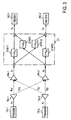
- Reference numerals P11-1, P11-2, P11-3 and P11-4 denote paths from the transmitting antenna TA-11 of the transmitting device 10-1 to the receiving antenna elements RA-1 to RA-4, respectively.
- Reference numerals P12-1,P12-2, P12-3 and P12-4 denote paths from the transmitting antenna TA-12 of the transmitting device 10-1 to the receiving antenna elements RA-1 to RA-4, respectively, Similarly, paths from the transmitting device 10-2 are denoted by P21-1 to P21-4 and P22-1 to P22-4.
- the N transmitting antennas TA-m1 to TA-mN of each transmitting device 10-m transmit signals at different carrier frequencies.
- the propagation characteristic is expressed as an impulse response of the propagation path, which is a function of frequency. Accordingly, propagation characteristics of the signals transmitted at different carrier frequencies usually differ from each other.
- the cross correlation between the received signals corresponding to each transmitted signal is called frequency correlation.
- the frequency correlation decreases with an increase in the carrier frequency difference between the two transmitted signals concerned. That is, different carrier frequencies of transmitters reduce the frequency correlation, causing a decrease in the cross correlation between signals received by the receiving array antenna. This permits adjacent placement of transmitting antennas.
- the transmitting antennas TA-11 and TA-12 in the same transmitting device 10-1 spaced the half-wave length apart transmit signals at the same carrier frequency over the paths P11-1 and P12-1 the correlation between two received signals by the receiving antenna RA-1 becomes very high.
- the cross correlation between the received signals could be reduced by choosing a proper carrier frequency difference between the two transmission signals with a view to decreasing the frequency correlation between the received signals. Since carrier frequencies of the plural transmitters differ in each transmitting device, the number of antennas may be reduced by combining transmission signals for each certain number of transmitters for application to one transmitting antenna.
- the M transmitting devices are spaced apart.
- the cross correlation in propagation characteristic between the signals transmitted from different transmitting devices is generally low. Accordingly, the use of the same carrier frequency for different transmitting devices permits multiplex transmission therefrom of plural signals at the same carrier frequency band.
- the spectrum of the signal transmitted from each transmitting antenna and the spectrum of the signal received by each receiving antenna element are shown adjacent the respective antennas in Fig. 2. All the transmission signals are transmitted over respective propagation paths and received by the receiving antenna elements RA-1 to RA-4.
- the transmission signals from the transmitting antennas TA-11 and TA-21 are multiplexed at the band of the center frequency f 1 .
- the transmission signals from the transmitting antennas TA-12 and TA-22 are multiplexed at the band of the center frequency f 2 .
- band signals of the carrier frequencies f 1 and f 2 are transmitted with their spectrums partly superimposed on each other.
- each received signal undergoes the following signal processing for interchannel interference cancellation and signal components of respective information sequences are separated. The principle of this operation will be described below with reference to Fig. 3.
- p ij a ij e j ⁇ ij
- w 11 represent a weighting coefficient of the path from the receiving antenna element RA-1 to the receiver RC-1
- w 12 a weighting coefficient of the path from the receiving antenna element RA-2 to the receiver RC-2
- w 21 a weighting coefficient of the path from the receiving antenna element RA-2 to the receiver RC-1
- w 22 a weighting coefficient of the path from the receiving antenna element RA-2 to the receiver RC-2
- W a weighting coefficient matrix.
- the present invention diagonalizes the matrix WP by manipulating the weighting coefficient matrix W .
- the weighting coefficient matrix W is adaptively controlled by using estimated transfer characteristics.
- an algorithm for adaptive control of the matrix W it is possible to use a zero-forcing, least square error, or similar criterion.
- These algorithms are commonly used for adaptive signal processing; in the present invention, too, they can similarly be used for signal processing.
- a description will be given of a method which uses a training signal as each transmission signal for initial convergence of the matrix W and updates the matrix W by the adaptive algorithm.
- Known signal sequences are separately transmitted, as transmission signals for weighting coefficient setting use, from the respective transmitters TR-1 and TR-2 to the antennas TA-1 and TA-2 and are received by the receivers RC-1 and RC-2, after which the weighting coefficient matrixes W are collectively calculated.
- the signals received by the receiving antenna elements RA-1 and RA-2 are detected intact by the receivers RC-1 and RC-2 without being combined each other.
- Px y and an estimated transfer function P' is adaptively determined in such a manner as to minimize an error between a replica P'x calculated from the function P' and the training signal x and the received signal y 1j , by which is obtained estimated transfer function values p' 11 and p' 22 for the training signal x.
- a training signal is transmitted from the transmitter TR-2 and an estimated matrix P' of the transfer function matrix P is similarly converged for the received signal y 2j .
- the following estimated transfer function matrix P' is obtained.
- P ⁇ p ⁇ 11 p ⁇ 21 p ⁇ 12 p ⁇ 22
- the matrix P' thus obtained is an estimated matrix of the transfer function of the path from the respective transmitters to the respective receiving antenna elements.
- P' P .
- Step 3 Assuming that the estimated matrix P' is ideal, an inverse matrix of the transfer function matrix P in which the matrix WP in Equation (9) is a unit matrix is calculated. Since the matrix in this example is, for example, a 2-by-2 matrix, the following matrix is obtained.
- the weighting coefficients w 11 to w 22 obtained from the estimated transfer function of the propagation path, obtained by the reception of the training sequence are used as initial values, and the weighting coefficients w 11 to w 22 are updated by an adaptive algorithm through use of the demodulated result (decoded result) as a reference signal, and the updated coefficients are set in the multipliers 21W11 to 21 W22 of the interchannel interference canceller 21, respectively.
- the weighting coefficient w 11 to w 22 may also be updated, for instance, at regular time intervals by an adaptive algorithm using a training signal or the demodulated results (decoded results) by the receivers RC-1 and RC-2.
- Fig. 3 does not impose any limitations on the transmitting carrier frequencies of the transmitters since the signals are transmitted from transmitting antennas at different positions. That is, the two transmitters TR-1 and TR-2 use the same frequency, but since the two transmitting antennas TA-1 and TA-2 are different in position, the received signals can be separated. What is more important is that even when transmission signals x 1 and x 2 are sent from the same antenna, if they are transmitted at different frequencies, their transfer functions in the propagation path differ, and consequently, received signals can be separated.
- Fig. 4 illustrates in block form an embodiment of the transmitting-station equipment according to the present invention.
- Each transmitting device of the transmitting-station equipment 100 includes N transmitters, each of which comprises a modulator and a carrier generator.
- Fig. 4 shows the case where the number of transmitting device M is two and the number of transmitters N is two.
- the transmitter TR-11 of the transmitting device 10-1 has a modulator 11-1, a frequency converter 12-1 and a carrier generator 13-1.
- an information sequence from an information sequence generator SG is separated by a serial-to-parallel converter (S/P) 15 into two signal sequences, which are input as different information sequences to the transmitters TR-11 and TR-12, respectively.
- S/P serial-to-parallel converter
- the other transmitters TR-12, TR-21 and TR-22 are also similarly configured.
- the carrier generator 13-1 generates a carrier signal of a preset frequency f L1 .
- the output from the modulator 11-1 is up-converted by the frequency converter 12-1 to the carrier frequency f L1 , and is fed to the transmitting antenna TA-11.
- the transmitter TR-12 of the same transmitting device 10-1 is identical in construction to the transmitter TR-11 except that it uses a carrier frequency f L2 different from that f L1 .
- the same combination of preset carrier frequencies f L1 and f L2 is used for the respective transmitting devices, but the carrier generator may preferably be a variable frequency type so as to deal with any combinations of carrier frequencies.
- Fig. 5 depicts in block form an example of the receiving device 20 corresponding to the transmitting-station equipment 100 of Fig. 4.
- the receiving device is shown to have four receiving antenna elements corresponding to the four transmitters in Fig. 4.
- the signals received by the antenna elements RA-1 to RA-4 are input to the interchannel interference canceller 21.
- the input signal may be an RF signal, signal down-converted to the IF band, base band signal, or digital signal A/D converted from such a signal; the basic configuration of the interchannel interference canceller does not change with the kind of input signal.
- the signal components of each information sequence separated by the interchannel interference canceller 21 are provided to the corresponding receivers RC-1 to RC-4, respectively.
- the receivers RC-1 to RC-4 generate, local signals of the frequencies f L1 and f L2 corresponding to the input signals are generated by local signal generators 25-1 to 25-4, and the received signals are converted by frequency converters 24-1 to 24-4 to the intermediate frequency or base band signals.
- the thus frequency-converted received signals are detected by demodulators 22-1 to 22-4 to regenerate signals z 1 , z 2 , z 3 and z 4 , which are applied to parallel-to-serial converters 26-1 and 26-2 to restore the two original information sequences.
- the detection method by the demodulators 22-1 to 22-4 may be a coherent detection, differential detection, or the like.
- the interchannel interference canceller 21 comprises: power dividers 21A-1 and 21A-2 for power-dividing input received signals from respective antenna elements to the number of all receivers; amplitude phase adjusting multipliers 21W11, 21W12, 21W21 and 21W22 for multiplying the outputs from the power dividers by weighting coefficients (tap coefficients) obtained by an adaptive algorithm for respective input-output paths; power combiners 21B-1 and 21B-2 for combining the amplitude phase modulated input signals; and a tap controller 21C for calculating tap coefficients and applying them to the amplitude phase adjusting multipliers 21W11 to 21W22.
- the tap coefficient controller 21C adaptively controls the weighting coefficients of the respective paths.
- the tap coefficient can be adaptively controlled by a conventional algorithm using a peak distortion or least square error criterion.
- the initial convergence values of the tap coefficients can be set as in the prior art by using the training signals transmitted from the transmitting side as described previously. This can be implemented by either analog or digital circuits.
- phase fluctuations or variations of the carriers used by the transmitters of the transmitting-station equipment 100 may become uniform, it is possible to use carrier generators connected to a local oscillator common to the transmitters of each transmitting device. It is also possible to operate the local oscillators in the respective transmitting devices in synchronism with a common local oscillator. For example, a GPS receiver is built in each transmitting device and a reference signal from a satellite is transmitted to each transmitting device to synchronize the common local oscillator in each transmitting device with the reference signal.
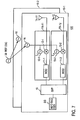
- FIG. 7 An example of such a configuration is shown in Fig. 7, in which the number of transmitting devices M is two.
- the illustrated example differs from the Fig. 4 example in that the transmitting devices 10-1 and 10-2 are each provided with a local oscillator 16 which generates a local signal in synchronization with a common reference signal generated by a reference oscillator 30.
- the transmitting device 10-1 provides the local signal from the local oscillator 16 to the carrier generators 13-1 and 13-2 of the transmitters TR-1 and TR-2, causing them to generate carriers of the frequencies f L1 and f L2 in synchronization with the reference signal.
- the transmitting device 10-2 is similarly configured. Thus, it is possible to make uniform the phase fluctuations or variations of the carriers among the transmitters TR-11, TR-12, TR21 and TR-22.
- Fig. 8 illustrates in block form an example of the receiving device 20 corresponding to the transmitting-station equipment of Fig. 7.
- a common oscillator 27 is provided to generate a common local signal, which is applied to the local signal generators 25-1 to 25-4, causing them to generate local signals of the frequencies f L1 and f L2 for down-conversion.
- the common local oscillator 27 is so configured as to generate the common local signal in synchronization with the reference signal from the reference oscillator 30 by GPS, for instance.
- the demodulated signals z 1 , z 2 , z 3 and z 4 from the demodulators 22-1 to 22-4 are fed back to the interchannel interference canceller 21, and they can be used as reference signals.
- the demodulated signals are applied to the parallel-to-serial converters 26-1 and 26-2 to restore the two original information sequences.
- Fig. 9 depicts a configuration provides increased signal separation accuracy by orthogonal coding.
- orthogonal coders 17-1 and 17-2 are provided in each transmitting device to improve the orthogonality of the transmission signals from the transmitting device.
- the orthogonal coder 17-1 is composed of a multiplier 17A-1 and an orthogonal code generator 17B-1.
- the other orthogonal coder 17-2 is also similarly configured.
- the orthogonal code generators 17B-1 and 17B-2 generate codes that are orthogonal to each other like spreading codes in CDMA communications, and in the multipliers 17A-1 and 17A-2 the information sequences are multiplied by such orthogonal codes, and the multiplied outputs are fed to the transmitters TR-11 and TR-12, respectively. This applies to the transmitting device 10-2.
- the orthogonal codes are all different from one another.
- the illustrated embodiment is identical in construction to the Fig. 4 embodiment except the above.
- Fig. 10 depicts the configuration of the receiving device 20 which receives transmission signals rendered into orthogonal codes in the transmitting-station equipment 100 of Fig. 9.
- the correlators 28A-1 to 28A-4 are supplied with the orthogonal codes from orthogonal code generators 28B-1 to 28B-4, respectively, so that they are correlated with the received signals.
- the orthogonal code generators 28B-1 to 28B-4 generate the same codes as those by the corresponding four orthogonal code generators in Fig.
- the input signals z 1 , z 2 , z 3 and z 4 superimposed on the orthogonal codes are separated.
- the illustrated embodiment is identical in construction and operation to the Fig. 5 embodiment except the above.
- the method described above is like an application of the spread spectrum communication method.
- a spreading gain by the sequence length of the orthogonal code can be obtained and the signal discrimination level can be increased accordingly-this permits implementation of more excellent communications even if the interchannel interference remains uncanceled.
- Fig. 11 illustrates in block form an embodiment of the transmitting-station equipment 100 using the error correcting code scheme, in which the orthogonal coders 17-1 and 17-2 in Fig. 9 are replaced with error correcting coders 18-1 and 18-2.
- the transmitting device 10-1 the information sequences to be transmitted are rendered by the error correcting coders 18-1 and 18-2 into error correcting codes, which are input to the transmitters TR-11 and TR-12.
- the transmitting device 10-2 is also similarly configured.
- Fig. 12 depicts the configuration of the receiving device 20 corresponding to the transmitting-station equipment 100 of Fig. 11.
- the illustrated embodiments uses decoders 29-1 to 29-4 as substitutes for the corresponding pairs of correlators 28A-1 to 28A-4 and orthogonal code generators 28B-1 to 28B-4.
- the outputs from the receivers RC-1 to RC-4 are decoded by the decoders 29-1 to 29-4 to obtain the received signals z 1 , z 2 , z 3 and z 4 , which are applied to the parallel-to-serial converters 26-1 and 26-2 to restore the original information sequences.
- the signal discrimination level could be raised by using, as the corresponding decoders, such maximum likelihood estimators as Viterbi decoders.
- any transmitting antennas can be used, but the cross correlation between the transfer characteristics of the transmission signals could be reduced by using an antenna of different polarization for each transmitting device.
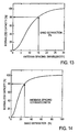
- Figs. 13 and 14 a description will be given of the effects of increased degree of signal separation and enhanced frequency utilization efficiency by slightly displacing the carrier frequencies which are generated in the plural transmitters of each transmitting device.
- the ratio of the difference ⁇ f between the center frequency f0 and f1 to the transmission bandwidth Ws is defined as the "band separation.”
- FIG. 13 depicts the normalized capacity with respect to the antenna spacing of the transmitter when the band separation is 0% (when the frequency bands used completely coincide). This suggests that even if the frequency bands of transmission signals from two transmitting antennas completely coincide, the signals could be received separately by providing a sufficiently wide antenna spacing. With an antenna spacing of about 0.5 wavelength, the normalized channel capacity is zero. To achieve a normalized channel capacity of 80% or so, the antenna spacing needs to be around 15 wavelengths.
- Fig. 14 shows the normalized capacity with respect to the band separation when the transmitting antenna spacing is 0.5 wavelength. Even when the transmitting antenna spacing is as close as approximately 0.5 wavelength, a normalized capacity of 80% can be achieved by shifting the carrier frequencies of the two transmitters from each other until the band separation reaches about 30%.
- Figs. 13, 14 and 16 show the results of evaluation obtained when the information sequences are not coded using the orthogonal codes, the characteristics could be further improved by orthogonal coding of the information sequences.
- the embodiments each have been described to use the receiving array antenna elements equal in number to the information sequences to be separated, that is, to the number of transmitters, the number of array antenna elements may be either smaller or larger.
- the number of power dividers (21A-1 and 21A-2) of the receiving device of Fig. 6 is also made equal to the number of receiving array antenna elements, and each power divider divides the received signal to signals of the same number as that of the information sequences and an amplitude phase adjusting multiplier is inserted in each signal path.
- the signal separation characteristic is improved accordingly.
- the signal separation characteristic is degraded accordingly, but it can be improved by using, for example, such an orthogonal coding technique as shown in Figs. 9 and 10, or such an error correcting code technique as shown in Figs. 11 and 12.
- the receiving device when the carrier frequencies of plural transmitters of the same transmitting device are slightly shifted from each other, even if the transmitting signal frequency bands substantially coincide with each other, the receiving device is able to separate the received signal by plural receiving antennas based on different transfer functions of respective paths.
Landscapes
- Engineering & Computer Science (AREA)
- Signal Processing (AREA)
- Computer Networks & Wireless Communication (AREA)
- Radio Transmission System (AREA)
- Noise Elimination (AREA)
- Mobile Radio Communication Systems (AREA)
Claims (8)
- Dispositif de réception comportant :une antenne réseau ayant N x M éléments (RA-1, ..., RA-K) destinés à recevoir des signaux émis par M ensembles de N porteuses de fréquences différentes portant des signaux respectivement modulés par des séquences d'informations différentes, les bandes des signaux desdites N porteuses se chevauchant, ledit N étant un entier égal ou supérieur à 2 et ledit M étant un entier égal ou supérieur à 1 ;un suppresseur (21) d'interférences entre canaux destiné à diviser des signaux reçus provenant desdits éléments de ladite antenne réseau en N x M signaux, à pondérer lesdits N x M signaux et à combiner lesdits N x M signaux pondérés et à séparer ledit signal combiné en N x M signaux ;N x M récepteurs (RC-1, ..., RC-K) ayant des démodulateurs (22-1, ..., 22-K) destinés à démoduler lesdits N x M signaux séparés ; etune unité (21C) de commande de coefficient destinée à commander des coefficients de pondération dudit suppresseur (21) d'interférences entre canaux pour minimiser la corrélation mutuelle entre des signaux de sortie provenant dudit suppresseur (21) d'interférences entre canaux ;caractérisé en ce que ledit suppresseur (21) d'interférences entre canaux comporte des diviseurs (21A-1, 21A-2) destinés chacun à diviser le signal reçu provenant de chacun desdits éléments (RA-1, ..., PA-K) de ladite antenne réseau en signaux égaux en nombre à des séquences d'informations devant être séparées, des multiplieurs (21W11, 21W22) destinés à multiplier lesdits signaux divisés par des coefficients de pondération, des unités de combinaison (21B-1, 21B-2) destinées à combiner lesdits signaux pondérés provenant de certains, différents, desdits éléments (RA-1, ..., RA-K) de l'antenne réseau pour générer des signaux combinés égaux en nombre auxdites séquences d'informations devant être séparées et pour appliquer lesdits signaux combinés auxdits récepteurs égaux en nombre auxdites séquences d'informations, et dans lequel ladite unité de commande (21C) de coefficient commande des coefficients de pondération devant être appliqués auxdits multiplieurs (21W11, 21W22) sur la base desdits signaux combinés, de façon à minimiser la corrélation mutuelle entre les signaux de sortie dudit suppresseur d'interférences entre canaux.
- Dispositif de réception selon la revendication 1, comportant en outre des corrélateurs (28B-1, 28A-1, ..., 28B4, 28A-4) prévus chacun à la sortie de chacun desdits récepteurs, pour restaurer l'une desdites séquences d'informations correspondant à un code orthogonal.
- Dispositif de réception selon la revendication 1, comportant en outre des décodeurs (29-1, 29-4) prévus chacun à la sortie de chacun desdits récepteurs (RC-1, RC-2) pour restaurer l'une desdites séquences d'informations correspondant à un code de correction d'erreur.
- Procédé pour une communication radio entre au moins un dispositif d'émission (10-1, ... 10-M) ayant N émetteurs (TA-11, ..., TA-1N) et N éléments d'antenne d'émission connectés chacun à la sortie de l'un, correspondant, desdits N émetteurs, et un dispositif de réception (RC-1, ..., RC-K) pourvu d'une antenne réseau ayant N éléments (RA-1, RA-K) d'antenne de réception et N récepteurs, ledit procédé comprenant les étapes suivantes qui consistent :du côté de l'émission,(a) à moduler différentes séquences d'informations dans lesdits émetteurs (TR-11, ..., TR-1N) et à convertir lesdites séquences d'informations modulées avec des fréquences porteuses différentes, chacune des bandes de signaux d'émission chevauchant au moins l'une des autres bandes de signaux d'émission ; etdu côté de la réception,caractérisé en ce que l'étape (c) comprend :(b) à recevoir plusieurs signaux à l'aide desdits N éléments (RA-1, RA-K) d'antenne de réception ;(c) à traiter lesdits signaux reçus pour minimiser la corrélation mutuelle entre lesdits signaux de sortie traités et à séparer des composantes respectives de signaux de séquences d'informations desdits signaux reçus ; et(d) à démoduler lesdites composantes de signaux de séquences d'informations séparées par plusieurs récepteurs afin de restaurer les séquences d'informations d'origine,la division du signal reçu provenant de chacun desdits éléments (RA-1, ..., PA-K) de ladite antenne réseau en signaux égaux en nombre à des séquences d'informations devant être séparées ;la multiplication desdits signaux divisés par des coefficients de pondération ;la combinaison desdits signaux pondérés provenant de certains, différents, desdits éléments (RA-1, ..., RA-K) de l'antenne réseau pour générer des signaux combinés égaux en nombre auxdites séquences d'informations devant être séparées ;la fourniture desdits signaux combinés auxdits récepteurs égaux en nombre auxdites séquences d'informations, etla commande de coefficients de pondération sur la base desdits signaux combinés, minimisant ainsi la corrélation mutuelle entre les signaux de sortie traités.
- Procédé selon la revendication 4, dans lequel M dispositifs d'émission (10-1, ..., 10-M) sont prévus à des intervalles du côté de l'émission, et dans lequel l'étape (a) comprend l'émission par chacun desdits N émetteurs de chacun desdits M dispositifs d'émission de N séquences d'informations différentes utilisant le même ensemble de fréquences porteuses différentes, et l'étape (b) comprend la réception, du côté de la réception, de signaux émis par N x M éléments (RA-1, RA-K) d'antenne de réception.
- Procédé selon la revendication 4 ou 5, qui comprend une étape consistant à émettre un signal d'enseignement connu depuis chacun desdits émetteurs (TR-11, ..., TR-1N), et ladite étape (c) comprend une étape de préréception dudit signal d'enseignement par ledit élément (RA-1, RA-K) d'antenne de réception de chaque dispositif de réception, de minimisation de ladite corrélation mutuelle en utilisant une séquence de signal d'enseignement connue en tant que signal de référence, et de séparation desdites séquences d'informations des signaux de séquences d'informations reçus ensuite.
- Procédé selon la revendication 4 ou 5, dans lequel ladite étape (a) comprend les étapes qui consistent :(a-1) à coder des séquences d'informations différentes par des codes orthogonaux différents dans plusieurs émetteurs (TR-11, ..., TR-1N) de chacun desdits dispositifs d'émission ; et(a-2) à moduler les signaux de sortie codés et à émettre lesdits signaux de sortie modulés à différentes fréquences porteuses avec des bandes de signaux d'émission qui se chevauchent ; etladite étape (d) comprend en outre une étape de restauration desdites séquences d'informations en détectant la corrélation entre lesdits signaux modulés et lesdits codes orthogonaux.
- Procédé selon la revendication 4 ou 5, dans lequel ladite étape (a) comprend les étapes qui consistent :(a-1) à coder des séquences d'informations différentes par des codes de correction d'erreur dans plusieurs émetteurs (TR-11, ..., TR-1N) de chacun desdits dispositifs d'émission ; et(a-2) à moduler les signaux de sortie codés et à émettre lesdits signaux de sortie modulés à des fréquences porteuses différentes, avec des bandes de signaux d'émission qui se chevauchent ; etladite étape (d) comprend en outre une étape de restauration desdites séquences d'informations en soumettant lesdits signaux démodulés à un décodage correspondant auxdits codes de correction d'erreur.
Applications Claiming Priority (2)
| Application Number | Priority Date | Filing Date | Title |
|---|---|---|---|
| JP2001379146A JP3992489B2 (ja) | 2001-12-12 | 2001-12-12 | 無線通信方法及びその装置 |
| JP2001379146 | 2001-12-12 |
Publications (3)
| Publication Number | Publication Date |
|---|---|
| EP1320212A2 EP1320212A2 (fr) | 2003-06-18 |
| EP1320212A3 EP1320212A3 (fr) | 2004-10-06 |
| EP1320212B1 true EP1320212B1 (fr) | 2006-12-06 |
Family
ID=19186642
Family Applications (1)
| Application Number | Title | Priority Date | Filing Date |
|---|---|---|---|
| EP20020027581 Expired - Lifetime EP1320212B1 (fr) | 2001-12-12 | 2002-12-10 | Procédé et dispositif de multiplexage fréquentiel avec anullation d'interférence |
Country Status (5)
| Country | Link |
|---|---|
| US (1) | US7227906B2 (fr) |
| EP (1) | EP1320212B1 (fr) |
| JP (1) | JP3992489B2 (fr) |
| CN (1) | CN1237734C (fr) |
| DE (1) | DE60216559T2 (fr) |
Families Citing this family (53)
| Publication number | Priority date | Publication date | Assignee | Title |
|---|---|---|---|---|
| FI20012581A0 (fi) * | 2001-12-27 | 2001-12-27 | Nokia Corp | Häiriönpoistomenetelmä kommunikaatiojärjestelmässä |
| JP4350491B2 (ja) * | 2002-12-05 | 2009-10-21 | パナソニック株式会社 | 無線通信システム、無線通信方法、及び無線通信装置 |
| JP2004254111A (ja) * | 2003-02-20 | 2004-09-09 | Sanyo Electric Co Ltd | アダプティブアレイ無線通信装置、アンテナ相関表示方法、アンテナ相関調整方法、アンテナ相関表示プログラム、およびアンテナ相関調整プログラム |
| JP4133531B2 (ja) * | 2003-04-15 | 2008-08-13 | シャープ株式会社 | 無線通信装置及び無線通信システム |
| JP2005027179A (ja) * | 2003-07-04 | 2005-01-27 | Toshiba Corp | 受信装置および受信回路 |
| US8204149B2 (en) * | 2003-12-17 | 2012-06-19 | Qualcomm Incorporated | Spatial spreading in a multi-antenna communication system |
| US8027417B2 (en) | 2003-12-19 | 2011-09-27 | Nortel Networks Limited | Interference-weighted communication signal processing systems and methods |
| US7336746B2 (en) * | 2004-12-09 | 2008-02-26 | Qualcomm Incorporated | Data transmission with spatial spreading in a MIMO communication system |
| US8169889B2 (en) | 2004-02-18 | 2012-05-01 | Qualcomm Incorporated | Transmit diversity and spatial spreading for an OFDM-based multi-antenna communication system |
| US20050180312A1 (en) * | 2004-02-18 | 2005-08-18 | Walton J. R. | Transmit diversity and spatial spreading for an OFDM-based multi-antenna communication system |
| US20050238111A1 (en) * | 2004-04-09 | 2005-10-27 | Wallace Mark S | Spatial processing with steering matrices for pseudo-random transmit steering in a multi-antenna communication system |
| US8923785B2 (en) * | 2004-05-07 | 2014-12-30 | Qualcomm Incorporated | Continuous beamforming for a MIMO-OFDM system |
| US8285226B2 (en) * | 2004-05-07 | 2012-10-09 | Qualcomm Incorporated | Steering diversity for an OFDM-based multi-antenna communication system |
| US7110463B2 (en) * | 2004-06-30 | 2006-09-19 | Qualcomm, Incorporated | Efficient computation of spatial filter matrices for steering transmit diversity in a MIMO communication system |
| US7978649B2 (en) | 2004-07-15 | 2011-07-12 | Qualcomm, Incorporated | Unified MIMO transmission and reception |
| US7233777B2 (en) * | 2004-08-31 | 2007-06-19 | L-3 Integrated Systems Company | Separation of AM cochannel signals in an overloaded signal environment |
| US7978778B2 (en) | 2004-09-03 | 2011-07-12 | Qualcomm, Incorporated | Receiver structures for spatial spreading with space-time or space-frequency transmit diversity |
| JP4440739B2 (ja) * | 2004-09-06 | 2010-03-24 | 株式会社エヌ・ティ・ティ・ドコモ | 周波数共用型送信機 |
| US20060063494A1 (en) * | 2004-10-04 | 2006-03-23 | Xiangdon Zhang | Remote front-end for a multi-antenna station |
| JP4802830B2 (ja) * | 2005-04-11 | 2011-10-26 | パナソニック株式会社 | 端末装置 |
| JP4327122B2 (ja) * | 2005-05-11 | 2009-09-09 | 株式会社東芝 | 無線受信機および無線受信方法 |
| WO2007004924A1 (fr) * | 2005-07-01 | 2007-01-11 | Telefonaktiebolaget Lm Ericsson (Publ) | Système de télécommunications sans fil à capacité améliorée de transmission |
| WO2007021056A1 (fr) * | 2005-08-19 | 2007-02-22 | Electronics And Telecommunications Research Institute | Procede d'estimation de voie et procede de creation d'un signal d'entrainement pour l'estimation des voies dans un systeme ofdm-mimo |
| US8543070B2 (en) | 2006-04-24 | 2013-09-24 | Qualcomm Incorporated | Reduced complexity beam-steered MIMO OFDM system |
| US8290089B2 (en) * | 2006-05-22 | 2012-10-16 | Qualcomm Incorporated | Derivation and feedback of transmit steering matrix |
| ATE469493T1 (de) * | 2006-08-21 | 2010-06-15 | Koninkl Philips Electronics Nv | Übertragungsverfahren und vorrichtungen zur unterdrückung der interferenzen zwischen trägern |
| EP1971043A1 (fr) | 2007-03-16 | 2008-09-17 | Sony Deutschland GmbH | Dispositif de transmission et procédé pour transmettre des signaux dans un système de communication sans fil, dispositif de réception et procédé pour la réception de signaux dans un système de communication sans fil |
| KR101454027B1 (ko) * | 2007-08-10 | 2014-10-24 | 한국전자통신연구원 | 병렬 구조를 가지는 시분할 다중화 통신 시스템 및 방법 |
| US8249513B2 (en) | 2007-08-13 | 2012-08-21 | Samsung Electronics Co., Ltd. | System and method for training different types of directional antennas that adapts the training sequence length to the number of antennas |
| GB2453147B (en) * | 2007-09-27 | 2009-11-18 | Toshiba Res Europ Ltd | A wireless transmission device |
| US20090121935A1 (en) * | 2007-11-12 | 2009-05-14 | Samsung Electronics Co., Ltd. | System and method of weighted averaging in the estimation of antenna beamforming coefficients |
| US8478204B2 (en) | 2008-07-14 | 2013-07-02 | Samsung Electronics Co., Ltd. | System and method for antenna training of beamforming vectors having reuse of directional information |
| JP5721316B2 (ja) * | 2009-03-03 | 2015-05-20 | シャープ株式会社 | 送信装置、受信装置および通信システム |
| FR2966665A1 (fr) * | 2010-10-22 | 2012-04-27 | France Telecom | Procede et dispositif de communication radio pour antennes d'usager multiples |
| CN103718376B (zh) * | 2011-06-06 | 2016-06-08 | 安德烈斯·彼得勒斯·克龙涅·福里 | 多波束多无线电天线 |
| TW201316709A (zh) * | 2011-10-12 | 2013-04-16 | Transystem Inc | 具一擴充模組之多重輸入多重輸出的無線通信系統 |
| TWI439066B (zh) * | 2012-02-15 | 2014-05-21 | Transystem Inc | 多重輸入多重輸出無線通訊系統之擴充模組 |
| JP2013251071A (ja) * | 2012-05-30 | 2013-12-12 | Advantest Corp | 信号測定装置、信号測定方法、プログラム、記録媒体 |
| CN103813346A (zh) * | 2012-11-08 | 2014-05-21 | 华为技术有限公司 | 一种通信信号传输方法、装置及系统 |
| EP2984884A1 (fr) | 2013-04-08 | 2016-02-17 | Telefonaktiebolaget LM Ericsson (publ) | Exécution de mesures inter-fréquences sur des porteuses ayant des bandes passantes se chevauchant |
| WO2014168539A1 (fr) * | 2013-04-08 | 2014-10-16 | Telefonaktiebolaget L M Ericsson (Publ) | Procédés permettant d'effectuer des mesures inter-fréquences en état de repos |
| JP6356345B2 (ja) * | 2015-05-14 | 2018-07-11 | 株式会社Nttドコモ | マルチバンドアレーアンテナ |
| CN105099643B (zh) * | 2015-08-18 | 2019-03-01 | 北京科技大学 | 一种全双工无线通信的方法、天线装置及系统 |
| US10236947B2 (en) * | 2016-02-19 | 2019-03-19 | Elwha Llc | System with transmitter and receiver configured to provide a channel capacity that exceeds a saturation channel capacity |
| US9800310B2 (en) * | 2016-02-19 | 2017-10-24 | Elwha Llc | Transmitter configured to provide a channel capacity that exceeds a saturation channel capacity |
| US9780853B2 (en) * | 2016-02-19 | 2017-10-03 | Elwha Llc | Receiver configured to provide a channel capacity that exceeds a saturation channel capacity |
| US10236955B2 (en) * | 2016-02-19 | 2019-03-19 | Elwha Llc | System with transmitter and receiver remote from one another and configured to provide a channel capacity that exceeds a saturation channel capacity |
| JP6299024B1 (ja) * | 2016-10-21 | 2018-03-28 | 株式会社国際電気通信基礎技術研究所 | 無線通信装置および無線通信方法 |
| US10425837B2 (en) | 2017-10-02 | 2019-09-24 | The Invention Science Fund I, Llc | Time reversal beamforming techniques with metamaterial antennas |
| US10833381B2 (en) | 2017-11-08 | 2020-11-10 | The Invention Science Fund I Llc | Metamaterial phase shifters |
| CN108135029A (zh) * | 2017-12-21 | 2018-06-08 | 深圳地空互联技术有限公司 | 一种应用于高速移动通信的方法、装置及系统 |
| US10200069B1 (en) | 2018-02-20 | 2019-02-05 | The Invention Science Fund I, Llc | Large area metamaterial antenna optimization |
| CN111951538A (zh) * | 2020-09-16 | 2020-11-17 | 江苏赛普光电科技有限公司 | 激光贴墙仪串频保护系统及其运行方法 |
Family Cites Families (11)
| Publication number | Priority date | Publication date | Assignee | Title |
|---|---|---|---|---|
| JP2508574B2 (ja) * | 1992-11-10 | 1996-06-19 | 日本電気株式会社 | 多チャンネルエコ―除去装置 |
| DE69432013T2 (de) * | 1993-10-12 | 2003-10-09 | Ntt Mobile Communications Network Inc., Tokio/Tokyo | Übertragungsverfahren mit mehreren stationen und empfänger dafür |
| US5640146A (en) * | 1995-02-24 | 1997-06-17 | Ntp Incorporated | Radio tracking system and method of operation thereof |
| US5710797A (en) * | 1995-05-23 | 1998-01-20 | Libit Signal Processing Inc. | Method and apparatus for digital communication in the presence of closely spaced adjacent channels |
| US5887037A (en) * | 1996-02-27 | 1999-03-23 | Lucent Technologies Inc. | Introducing processing delay as a multiple of the time slot duration |
| JP2914445B2 (ja) * | 1997-08-05 | 1999-06-28 | 日本電気株式会社 | Cdma適応受信装置 |
| US6714608B1 (en) * | 1998-01-27 | 2004-03-30 | Broadcom Corporation | Multi-mode variable rate digital satellite receiver |
| JP3609937B2 (ja) | 1998-03-20 | 2005-01-12 | シャープ株式会社 | 受信機 |
| JP3894468B2 (ja) | 1999-12-16 | 2007-03-22 | Kddi株式会社 | スペクトラム拡散通信方法 |
| JP2001267991A (ja) * | 2000-03-16 | 2001-09-28 | Sony Corp | 送信装置、送信方法、通信システム及びその通信方法 |
| US6999538B2 (en) * | 2001-09-10 | 2006-02-14 | Mitsubishi Electric Research Laboratories, Inc. | Dynamic diversity combiner with associative memory model for recovering signals in communication systems |
-
2001
- 2001-12-12 JP JP2001379146A patent/JP3992489B2/ja not_active Expired - Fee Related
-
2002
- 2002-12-10 DE DE2002616559 patent/DE60216559T2/de not_active Expired - Lifetime
- 2002-12-10 EP EP20020027581 patent/EP1320212B1/fr not_active Expired - Lifetime
- 2002-12-11 CN CNB021559740A patent/CN1237734C/zh not_active Expired - Fee Related
- 2002-12-11 US US10/315,993 patent/US7227906B2/en not_active Expired - Lifetime
Also Published As
| Publication number | Publication date |
|---|---|
| DE60216559D1 (de) | 2007-01-18 |
| CN1237734C (zh) | 2006-01-18 |
| JP3992489B2 (ja) | 2007-10-17 |
| US7227906B2 (en) | 2007-06-05 |
| EP1320212A2 (fr) | 2003-06-18 |
| DE60216559T2 (de) | 2007-06-21 |
| JP2003179567A (ja) | 2003-06-27 |
| CN1426171A (zh) | 2003-06-25 |
| US20030123565A1 (en) | 2003-07-03 |
| EP1320212A3 (fr) | 2004-10-06 |
Similar Documents
| Publication | Publication Date | Title |
|---|---|---|
| EP1320212B1 (fr) | Procédé et dispositif de multiplexage fréquentiel avec anullation d'interférence | |
| RU2216866C2 (ru) | Способ и устройство для передачи данных в системе с множеством несущих частот | |
| KR960012426B1 (ko) | 스프레드 스펙트럼 노이즈 제거 방법 및 장치 | |
| CA2174344C (fr) | Transmission de signaux a vitesse variable dans un systeme de communications a spectre etale utilisant le codage d'ensembles secondaires | |
| EP0599500B1 (fr) | Emetteur et récepteur en diversité de fréquence | |
| US6952455B1 (en) | Adaptive antenna method and apparatus | |
| US7164696B2 (en) | Multi-carrier CDMA communication device, multi-carrier CDMA transmitting device, and multi-carrier CDMA receiving device | |
| US8583068B2 (en) | Interference reduction for multiple signals | |
| US6549582B1 (en) | Method and apparatus for combining transponders on multiple satellites into virtual channels | |
| US7072409B2 (en) | Space multiplex radio communication method and radio communication apparatus | |
| US20030013468A1 (en) | Radio communication system | |
| EP0807345B1 (fr) | Procede de transmission de donnees amrc, emetteur et recepteur avec supersymbole pour eliminer les interferences | |
| EP1667340A1 (fr) | Procede de communication protegee, appareil de transmission et appareil de reception | |
| US7693140B2 (en) | CDMA transmitting apparatus and CDMA receiving apparatus | |
| US7072410B1 (en) | Multiple access system and method for multibeam digital radio systems | |
| KR20010106445A (ko) | 스택 캐리어 이산 다중 톤 통신기술 | |
| KR101011751B1 (ko) | 수신기에서의 신호 분리를 지원하기 위한 복수의 동시 전송기를 위한 기복형 전송 패턴 | |
| CN101563849B (zh) | 波动传输场型以支持接收器处的信号分离 | |
| WO1996014699A1 (fr) | Techniques de diversite d'antennes | |
| WO1998056123A1 (fr) | Systeme et procede faisant appel a des signaux amdc polarises | |
| WO2005002067A2 (fr) | Ondes porteuses multiples a spectre etale utilisant une modification non lineaire de bandes sous-porteuses | |
| JPH0758727A (ja) | 周波数ダイバーシチ伝送装置 | |
| JP4091270B2 (ja) | 空間多重無線通信方法及び無線通信装置 | |
| EP1216515A2 (fr) | Communications dans un systeme amcr | |
| WO2002003641A1 (fr) | Emetteur cofdm avec diversite et retard |
Legal Events
| Date | Code | Title | Description |
|---|---|---|---|
| PUAI | Public reference made under article 153(3) epc to a published international application that has entered the european phase |
Free format text: ORIGINAL CODE: 0009012 |
|
| 17P | Request for examination filed |
Effective date: 20021210 |
|
| AK | Designated contracting states |
Designated state(s): AT BE BG CH CY CZ DE DK EE ES FI FR GB GR IE IT LI LU MC NL PT SE SI SK TR |
|
| AX | Request for extension of the european patent |
Extension state: AL LT LV MK RO |
|
| PUAL | Search report despatched |
Free format text: ORIGINAL CODE: 0009013 |
|
| AK | Designated contracting states |
Kind code of ref document: A3 Designated state(s): AT BE BG CH CY CZ DE DK EE ES FI FR GB GR IE IT LI LU MC NL PT SE SI SK TR |
|
| AX | Request for extension of the european patent |
Extension state: AL LT LV MK RO |
|
| 17Q | First examination report despatched |
Effective date: 20050120 |
|
| AKX | Designation fees paid |
Designated state(s): DE GB |
|
| RTI1 | Title (correction) |
Free format text: METHOD AND APPARATUS FOR FREQUENCY MULTIPLEXING WITH INTERFERENCE CANCELLATION |
|
| GRAP | Despatch of communication of intention to grant a patent |
Free format text: ORIGINAL CODE: EPIDOSNIGR1 |
|
| GRAS | Grant fee paid |
Free format text: ORIGINAL CODE: EPIDOSNIGR3 |
|
| GRAA | (expected) grant |
Free format text: ORIGINAL CODE: 0009210 |
|
| AK | Designated contracting states |
Kind code of ref document: B1 Designated state(s): DE GB |
|
| REG | Reference to a national code |
Ref country code: GB Ref legal event code: FG4D |
|
| REF | Corresponds to: |
Ref document number: 60216559 Country of ref document: DE Date of ref document: 20070118 Kind code of ref document: P |
|
| PLBE | No opposition filed within time limit |
Free format text: ORIGINAL CODE: 0009261 |
|
| STAA | Information on the status of an ep patent application or granted ep patent |
Free format text: STATUS: NO OPPOSITION FILED WITHIN TIME LIMIT |
|
| 26N | No opposition filed |
Effective date: 20070907 |
|
| PGFP | Annual fee paid to national office [announced via postgrant information from national office to epo] |
Ref country code: DE Payment date: 20181127 Year of fee payment: 17 |
|
| PGFP | Annual fee paid to national office [announced via postgrant information from national office to epo] |
Ref country code: GB Payment date: 20181205 Year of fee payment: 17 |
|
| REG | Reference to a national code |
Ref country code: DE Ref legal event code: R119 Ref document number: 60216559 Country of ref document: DE |
|
| GBPC | Gb: european patent ceased through non-payment of renewal fee |
Effective date: 20191210 |
|
| PG25 | Lapsed in a contracting state [announced via postgrant information from national office to epo] |
Ref country code: DE Free format text: LAPSE BECAUSE OF NON-PAYMENT OF DUE FEES Effective date: 20200701 Ref country code: GB Free format text: LAPSE BECAUSE OF NON-PAYMENT OF DUE FEES Effective date: 20191210 |