EP1320253A2 - Transformation de couleurs dans l'espace couleur tridimensionel - Google Patents
Transformation de couleurs dans l'espace couleur tridimensionel Download PDFInfo
- Publication number
- EP1320253A2 EP1320253A2 EP02258356A EP02258356A EP1320253A2 EP 1320253 A2 EP1320253 A2 EP 1320253A2 EP 02258356 A EP02258356 A EP 02258356A EP 02258356 A EP02258356 A EP 02258356A EP 1320253 A2 EP1320253 A2 EP 1320253A2
- Authority
- EP
- European Patent Office
- Prior art keywords
- matrix
- black
- white
- rgb pixel
- tetrahedron
- Prior art date
- Legal status (The legal status is an assumption and is not a legal conclusion. Google has not performed a legal analysis and makes no representation as to the accuracy of the status listed.)
- Withdrawn
Links
Images


Classifications
-
- H—ELECTRICITY
- H04—ELECTRIC COMMUNICATION TECHNIQUE
- H04N—PICTORIAL COMMUNICATION, e.g. TELEVISION
- H04N1/00—Scanning, transmission or reproduction of documents or the like, e.g. facsimile transmission; Details thereof
- H04N1/46—Colour picture communication systems
- H04N1/56—Processing of colour picture signals
- H04N1/60—Colour correction or control
- H04N1/6016—Conversion to subtractive colour signals
- H04N1/6019—Conversion to subtractive colour signals using look-up tables
-
- G—PHYSICS
- G06—COMPUTING OR CALCULATING; COUNTING
- G06T—IMAGE DATA PROCESSING OR GENERATION, IN GENERAL
- G06T11/00—Two-dimensional [2D] image generation
- G06T11/10—Texturing; Colouring; Generation of textures or colours
-
- G—PHYSICS
- G09—EDUCATION; CRYPTOGRAPHY; DISPLAY; ADVERTISING; SEALS
- G09G—ARRANGEMENTS OR CIRCUITS FOR CONTROL OF INDICATING DEVICES USING STATIC MEANS TO PRESENT VARIABLE INFORMATION
- G09G5/00—Control arrangements or circuits for visual indicators common to cathode-ray tube indicators and other visual indicators
- G09G5/02—Control arrangements or circuits for visual indicators common to cathode-ray tube indicators and other visual indicators characterised by the way in which colour is displayed
-
- G—PHYSICS
- G09—EDUCATION; CRYPTOGRAPHY; DISPLAY; ADVERTISING; SEALS
- G09G—ARRANGEMENTS OR CIRCUITS FOR CONTROL OF INDICATING DEVICES USING STATIC MEANS TO PRESENT VARIABLE INFORMATION
- G09G2320/00—Control of display operating conditions
- G09G2320/06—Adjustment of display parameters
- G09G2320/0693—Calibration of display systems
Definitions
- the present invention relates to the field of computer graphics and, more specifically, to the field of color transformation.
- CTR Cathode Ray Tube
- LCD Liquid Crystal Display
- PDP Plasma Display Panel
- 3D LUT 3D lookup table
- This technique uses a table defining a corresponding output color for each input color.
- the 3D LUT technique requires vast amounts of memory to store the entire table.
- the initial creation of the table can take a long period of time.
- Another color transformation technique involves the use of matrix calculation. This technique uses a matrix function that is applied to an input color to produce an output color. The matrix calculation technique, however, reduces the gamut of colors that can be produced by the output device. In addition, this technique transforms the input color into another color space before transforming the input color into the default color space. This is computationally intensive and time-consuming.
- a method, system and computer readable medium for transforming three dimensional (3D) color information into a color standard is described.
- a 3D cube defined by eight RGB color points representing the eight vertices of the 3D cube is stored. Each of the eight points represents one of the colors: red, yellow, white, magenta, blue, black, green and cyan.
- each of the eight points represents the difference between the capacity of a display and the color standard.
- the 3D cube is divided into six tetrahedrons and the tetrahedron corresponding to an input RGB pixel is selected.
- a 3x3 matrix based on the vertices of the selected tetrahedron is calculated. The 3x3 matrix is then multiplied by the components of the input RGB pixel to produce an output RGB pixel conforming to the color standard.
- FIG. 1 is a block diagram illustrating the overall system 100 architecture of an embodiment of the present invention.
- FIG. 1 shows graphics 102, an Operating System (OS) 104, a device driver 106, output device hardware 108, a transformer 110 and an output device 112.
- Graphics 102 are any images that can be shown on output device 112.
- Graphics 102 are produced by a computer application program such as a video game, a broadcaster such as a television station, or any other entity capable of producing an image and providing it to system 100 via a communications path.
- System 100 is a system for displaying graphics 102 on output device 112.
- system 100 is a television or monitor for processing images that are received via a radio frequency, a satellite transmission, cable, telephone, Ethernet or any other communications path.
- system 100 is a personal computer (PC) (e.g., an IBM or compatible PC workstation running the Microsoft Windows 95/98/2000/CE/NT/XP operating system, a Macintosh computer running the Mac OS operating system, or a SUN workstation running the UNIX operating system), a Personal Digital Assistant (PDA) (e.g., a PalmPilot running the Palm OS operating system), a game console (e.g., a Microsoft Xbox console or a Sony Playstation 2 console) or interactive television.
- system 100 is a camcorder (e.g., a Sony MiniDV camcorder) or a mobile phone capable of displaying color images.
- OS 104 is the operating system for system 100, i.e., the low-level software which handles the interface to peripheral hardware, schedules tasks, allocates storage, and presents a default interface to the user when no computer application program is running.
- OS 104 is the Microsoft Windows 95/98/2000/CE/NT/XP operating system, the Macintosh operating system, the UNIX operating system, the LINUX operating system or any other software capable of performing the tasks of an operating system.
- OS 104 is implemented in hardware, software or any combination of the two.
- Output device 112 is any device capable of displaying a color image.
- output device 112 is a television set, a computer monitor, a laptop display, a DVD player display, a PDA display, a camcorder display, a mobile phone display or a printer.
- output device 112 is a Cathode Ray Tube (CRT), a Liquid Crystal Display (LCD), a plasma display, an organic Light Emitting Device (LED) or any other electrical, optical, biological, chemical or mechanical device capable of displaying a color image. While only one output device 112 is shown in FIG. 1 for ease of explanation, the system 100 may support any number of output devices 112.
- Output device hardware 108 is any hardware used in conjunction with output device 112 for displaying images.
- Output device hardware 108 includes such hardware units as a graphics card (such as an Nvidia GeForce II graphics card), a graphics controller located within a CRT, or a printer controller.
- Device driver 106 is the unit capable of controlling, or driving, the output device hardware 108.
- Device driver 106 provides a level of abstraction between the output device hardware 108 and the OS 104. As such, device driver 106 allows higher level OS calls to interact with functions and elements specific to output device hardware 108.
- Device driver 106 is implemented in hardware, software or any combination of the two.
- Transformer 110 represents the substantive functions of the present invention.
- Transformer 110 performs the transformation of an input RGB pixel into an output RGB pixel conforming to the standard color space. The functions performed by transformer 110 are described in greater detail below.
- Transformer 110 is implemented in hardware, software or any combination of the two.
- transformer 110 resides in OS 104, device driver 106, any element of output device hardware 108 or any combination of the above.
- transformer 110 is a separate entity that interacts with OS 104, device driver 106, any element of output device hardware 108 or any combination of the above.
- FIG. 1 The operation system 100 of FIG. 1 according to one embodiment of the present invention is shown in the flowcharts of FIGs. 2 and 3.
- the RGB color space represents a closed set of colors defined by RGB color points.
- the RGB color space is a system of defining colors by their Red, Green and Blue components. Thus, every color in the RGB color space is defined by three values - the Red component, the Green component and the Blue component.
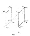
- FIG. 4 is an illustration of a 3D cube 400 representing the RGB color space, in one embodiment of the present invention.
- FIG. 4 shows the eight color points generally known in the art to represent the boundaries of the RGB color space.
- Each of the eight color points defines a limit vertex of the 3D cube 400 representing the RGB color space.
- the vertices of the 3D cube 400 are denoted as "limit vertices" because these vertices define the boundaries, or limits, of the color space.
- 3D cube 400 has as its vertices: red vertex 402, yellow vertex 404, white vertex 416, magenta vertex 412, black vertex 414, green vertex 406, cyan vertex 408 and the blue vertex 410. Each vertex is, in turn, defined by three color components.
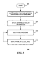
- FIG. 2 is a flowchart depicting the overall operation and control flow 200 of one embodiment of the present invention.
- Flow 200 describes generally the functions performed by transformer 110 in FIG. 1.
- Control flow 200 begins with step 202 and flows directly to step 204.
- step 204 the difference, or delta, between the capacity of the output device and the color standard is determined.
- This step requires testing to be performed on the output device 112.
- the testing consists of producing certain test color points on the output device 112 and measuring the color of the test color points with a device such as a colorimeter. These measurements are then compared to control measurements.
- a control measurement is a measurement that is taken from a color-standard-conforming output device displaying the same color point.
- a difference, or delta is calculated between the measurements taken from the output device 112 and the control measurement. More specifically, for each RGB component of a test color point, a delta is calculated between the measurements taken from the output device 112 and the control measurement.
- the result of the testing is a set of eight color point deltas, with each color point delta consisting of three components - a Red component, a Green component and a Blue component.
- a delta measurement is taken for each of the following test color points: red, yellow, white, magenta, blue, black, green and cyan. Specifically, a delta measurement is taken for each component of each test color point - a Red component, a Green component and a Blue component. In an embodiment of the present invention, the delta measurements for each of the eight test color points are then combined to define the vertices of a 3D cube representing a color space symbolizing the delta between the capacity of the output device and the color standard.
- this 3D cube will be referred to as the "delta 3D cube.”
- the eight RGB points defining the vertices of the delta 3D cube are defined by RGB triplets as shown in equations (2).
- the manner in which eight color points define the vertices of a 3D cube representing a color space is defined in greater detail in FIG. 4 above.
- step 206 the delta measurements (i.e., the delta 3D cube) calculated in step 204 above are stored.
- the delta measurements are later used by the transformer 110 when transforming RGB input pixels to output RGB pixels conforming to the color standard.
- an input RGB pixel is provided to transformer 110.
- step 210 an output pixel conforming to the color standard and corresponding to the input pixel is calculated in a transformation process.
- steps 204 and 206 are not performed by transformer 110.
- the delta measurements are taken by a third party and stored in transformer 110 or in any other location to which transformer 110 has access.
- Transformer 110 does not participate in the process of testing the output device 112 and simply uses the results of the testing, i.e., the delta measurements.
- steps 204 and 206 are performed by a third party and control flows directly from step 202 to step 208.
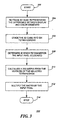
- FIG. 3 is a flowchart depicting the operation and control flow of the transformation process, in one embodiment of the present invention.
- Flow 300 describes generally the transformation process performed by transformer 110 in step 210 of FIG. 2.
- Control flow 300 begins with step 302 and flows directly to step 304.
- step 304 the delta measurements calculated and stored in steps 204 and 206 of FIG. 2 above are retrieved by transformer 110.
- transformer 110 retrieves eight RGB color points defining the vertices of a delta 3D cube representing a color space symbolizing the differences between the capacity of the output device and the color standard.
- An example of the eight RGB color points retrieved by transformer 110 is shown in equations (2) above.
- step 306 the delta 3D cube represented by the eight retrieved RGB color points is divided into six equal tetrahedrons.
- a tetrahedron is a 3D shape defined by four points in 3D, where all of the points are not coplanar.
- the delta 3D cube is divided into six tetrahedrons such that the following three conditions are met: I) all tetrahedrons are equal; II) each of the six tetrahedrons are defined by four vertices of the 3D cube; and III) all tetrahedrons share the black-to-white edge.
- the division of a 3D cube into six equal tetrahedrons in this fashion is described in greater detail below.
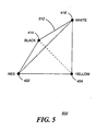
- FIG. 5 is an illustration of one of the six equal tetrahedrons within the 3D cube 400 shown in FIG. 4, in one embodiment of the present invention.
- Tetrahedron 500 shows that condition II is met because all of its vertices are vertices of the 3D cube 400.
- Tetrahedron 500 has the following vertices: red vertex 402, white vertex 416, yellow vertex 404 and black vertex 414.
- Tetrahedron 500 also shows that condition III is met because the black-to-white edge 420 is an edge of the tetrahedron. The remaining five tetrahedrons within 3D cube 400 are defined in the same fashion.
- Tetrahedron 1 (Red 402, Yellow 404, Black 414, White 416); Tetrahedron 2: (Red 402, Magenta 412, Black 414, White 416); Tetrahedron 3: (Green 406, Yellow 404, Black 414, White 416); Tetrahedron 4: (Green 406, Cyan 408, Black 414, White 416); Tetrahedron 5: (Blue 410, Magenta 412, Black 414, White 416); Tetrahedron 6: (Blue 410, Cyan 408, Black 414, White 416);
- the delta 3D cube represented by the eight retrieved RGB color points is divided into six tetrahedrons which are not necessarily equal.
- the delta 3D cube is divided into six tetrahedrons such that only one condition is met: every point within the 3D cube is located within only one tetrahedron.
- transformer 110 determines which of the six equal tetrahedrons within the delta 3D cube (as defined in step 306) corresponds to the input RGB pixel provided in step 208 of FIG. 2 above.
- the tetrahedron corresponding to the input RGB pixel is the tetrahedron in which the input RGB pixel is located according to 3D cube 400 of FIG. 4. That is, if the 3D cube 400 were divided into six equal tetrahedrons as described above, the tetrahedron corresponding to the input RGB pixel is the tetrahedron within which the coordinates of the input RGB pixel lie.
- a 3x3 matrix is calculated based on the vertices of the tetrahedron (within the delta 3D cube) that corresponds to the input RGB pixel.
- the coefficients of the first row of the 3x3 matrix are based on a first edge of the tetrahedron
- the coefficients of the second row of the 3x3 matrix are based on a second edge of the tetrahedron
- the coefficients of the third row of the 3x3 matrix are based on a third edge of the tetrahedron.
- none of the coefficients of the 3x3 matrix are based on the black-to-white-edge 420 of the tetrahedron.
- step 312 the 3x3 matrix calculated in step 310 above is multiplied by the input RGB pixel (defined in equation (3) above). This step is shown below: As explained above, the result of flow 300 is an output RGB pixel defined in equation (4) above. The result of the multiplying step 312 is three components, wherein each component represents a component of the output RGB pixel.
- the result of the multiplying step 312 is offset by the value of the input RGB pixel and by the value of the black vertex of the delta 3D cube.
- each component value of the output RGB pixel is offset by the corresponding component of the input RGB pixel and the corresponding component of the black vertex of the delta 3D cube.
- the delta 3D cube consists only of a 3x3 matrix wherein each coefficient of the matrix consists of three components. This relatively small amount of information is the only data necessary to transform an input RGB pixel into an output RGB pixel conforming to a color standard. This is an improvement over the large 3D look up table used by the 3D LUT table technique of the prior art described above.
- the small size of the delta 3D cube of the present invention results in an efficient color transformation.
- Another feature of the present invention is the lack of a reduction in the gamut of colors produced by the transformation in the output device.
- the output of the system of the present invention encompasses the entire gamut of colors that can be produced by the input RGB pixels. This feature results in greater accuracy of colors that are produced in the output device by the transformation technique.
- Yet another feature of the present invention is the mapping of the input RGB pixel directly into the color space of the color standard.
- the system of the present invention does not map a input RGB pixel into an intermediary color space before mapping the input RGB pixel into the color space of the color standard. This feature results in fewer calculations and less computing time. This leads to greater efficiency in performing the transformation function.
- Yet another feature of the present invention is a reduction in computing power necessary for performing the transformation, in contrast to the matrix multiplication techniques available in the prior art.
- the transformation process of the present invention requires the calculation of the simple (and computationally inexpensive) inequalities of equations (6).
- step 310 computationally inexpensive subtractions of equations (7) are calculated.
- step 312 computationally inexpensive auditions and multiplications (i.e., matrix multiplication) of equation (10) are calculated. This feature results in fewer calculations and less computing time. This leads to greater efficiency in performing the transformation function.
- the 3D cube 400 is divided into eight equal cubes, each of which is then subdivided into six equal tetrahedrons.
- This embodiment provides an alternative to the transformation process of flow 300 of FIG. 3.
- steps 302 and 304 of flow 300 are executed.
- 3D cube 400 is divided into eight equal cubes before step 306.
- Each of the eight cubes is then subdivided into six equal tetrahedrons, similar to step 306.
- steps 308 to 314 are executed.
- an additional number of calculations are performed (compared to flow 300), however greater accuracy and resolution results.
- the 3D cube 400 is divided into any number of equal cubes, each of which is then subdivided into six equal tetrahedrons. This is proceeded with steps similar to steps 306 to 314.
- FIG. 7 is an illustration of a divided three-dimensional cube 700 representing a color space, in an embodiment of the present invention.
- 3D cube 700 is similar to 3D cube 400 in that eight RGB points (or limit vertices) are used to represent a color space.
- 3D cube 700 shows the 3D cube is divided into eight sub-cubes during the transformation process - whereas 3D cube 400 is not divided into smaller cubes.
- 3D cube 700 represents the embodiment of the present invention, wherein a 3D cube is divided into eight equal cubes, each of which is then subdivided into six equal tetrahedrons (as described above).
- variable "k” represents the number of points necessary to represent a 3D cube in one of the three dimensions.
- any dimension i.e., any line consisting of an edge of the 3D cube
- 3D cube 700 which has been divided into eight sub-cubes
- any dimension i.e., any line consisting of an edge of the 3D cube
- 3D cube 700 can be shown that any dimension (i.e., any line consisting of an edge of the 3D cube) can be minimally defined by three points - the two endpoints of any edge, plus an additional midpoint of the edge, at the separation between two sub-cubes.
- two points are necessary to represent the 3D cube in one dimension.
- Yet another feature of the present invention is the more efficient retrieval of stored values, in contrast to the prior art.
- the following method of retrieving requires a reduced number of bits.
- N number of values (wherein N is a base ten number) requires a number of bits x, such that x is defined by: 2 x-1 ⁇ N ⁇ 2 x
- the determination of the location of the input RGB pixel within the divided cube conventionally requires four bits (referring to equation 16). In an embodiment of the present invention, the number of bits necessary for this determination is reduced. Using the most significant bit of each of the three components of the input RGB pixel, the location of the input RGB pixel within the 3D cube can be determined. The first bit is used to determine whether the pixel is located within the top four sub-cubes or the bottom four sub-cubes. The second bit is used to determine whether the pixel is located within the right two sub-cubes, or the left two sub-cubes, of the remaining four sub-cubes.
- the third bit is used to determine whether the pixel is located within the front sub-cube, or the back sub-cube, of the remaining two sub-cubes. In this fashion, a reduced number of bits (three bits as opposed to four bits) is used to retrieve the desired information. This retrieval method is also used upon retrieval of the delta cube in step 304 of FIG. 3.
- the present invention (i.e., system 100, flows 200, 300 or any part thereof) is implemented using hardware, software or a combination thereof and is implemented in one or more computer systems or other processing systems.
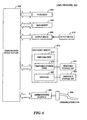
- An example of a computer system 600 is shown in FIG. 6.
- the computer system 600 represents any single or multi-processor computer. In conjunction, single-threaded and multi-threaded applications are used. Unified or distributed memory systems are used.
- the present invention is implemented in a multi-platform (platform independent) programming language such as Java, programming language/structured query language (PL/SQL), hyper-text mark-up language (HTML), practical extraction report language (PERL), Flash programming language, common gateway interface/structured query language (CGI/SQL) or the like.
- Java-enabled and JavaScript-enabled browsers are used, such as, Netscape, HotJava, and Microsoft Explorer browsers.
- Active content web pages can be used. Such active content web pages include Java applets or ActiveX controls, or any other active content technology developed now or in the future.
- the present invention is not intended to be limited to Java, JavaScript, or their enabled browsers, and are implemented in any programming language and browser, developed now or in the future, as would be apparent to a person skilled in the relevant art(s) given this description.
- the present invention is implemented using a high-level programming language (e.g., C++) and applications written for the Microsoft Windows NT or SUN OS environments. It will be apparent to persons skilled in the relevant art(s) how to implement the invention in alternative embodiments from the teachings herein.
- a high-level programming language e.g., C++
- applications written for the Microsoft Windows NT or SUN OS environments e.g., C++
- Computer system 600 includes one or more processors, such as processor 604.
- processors 604 execute software implementing the routines of the invention, described above.
- Each processor 604 is connected to a communication infrastructure 602 (e.g., a communications bus, cross-bar, or network).
- a communication infrastructure 602 e.g., a communications bus, cross-bar, or network.
- Computer system 600 includes an output device interface 608 that forwards graphics, text, and other data from the communication infrastructure 602 (or from a frame buffer not shown) for display on the output device 610.
- Computer system 600 also includes a main memory 606, preferably random access memory (RAM), and also includes a secondary memory 612.
- the secondary memory 612 includes, for example, a hard disk drive 614 and/or a removable storage drive 616, representing a floppy disk drive, a magnetic tape drive, an optical disk drive, etc.
- the removable storage drive 616 reads from and/or writes to a removable storage unit 618 in a well known manner.
- Removable storage unit 618 represents a floppy disk, magnetic tape, optical disk, etc., which is read by and written to by removable storage drive 616.
- the removable storage unit 618 includes a computer usable storage medium having stored therein computer software and/or data.
- secondary memory 612 includes other similar means for allowing computer programs or other instructions to be loaded into computer system 600.
- Such means include, for example, a removable storage unit 622 and an interface 620.
- Examples include a program cartridge and cartridge interface (such as that found in video game console devices), a removable memory chip (such as an EPROM, or PROM) and associated socket, and other removable storage units 622 and interfaces 620 which allow software and data to be transferred from the removable storage unit 622 to computer system 600.
- Computer system 600 also includes a communications interface 624.
- Communications interface 624 allows software and data to be transferred between computer system 600 and external devices via communications path 626.
- Examples of communications interface 624 include a modem, a network interface (such as Ethernet card), a communications port, interfaces described above, etc.
- Software and data transferred via communications interface 624 are in the form of signals which are electronic, electromagnetic, optical or other signals capable of being received by communications interface 624, via communications path 626.
- communications interface 624 provides a means by which computer system 600 interfaces to a network such as the Internet.
- the present invention is implemented using software running (that is, executing) in an environment similar to that described above.
- computer program product is used to generally refer to removable storage unit 618, a hard disk installed in hard disk drive 614, or a carrier wave carrying software over a communication path 626 (wireless link or cable) to communication interface 624.
- a computer useabie medium includes magnetic media, optical media, or other recordable media, or media that transmits a carrier wave or other signal.
- Computer programs are stored in main memory 606 and/or secondary memory 612. Computer programs are also received via communications interface 624. Such computer programs, when executed, enable the computer system 600 to perform the features of the present invention as discussed herein. In particular, the computer programs, when executed, enable the processor 604 to perform features of the present invention. Accordingly, such computer programs represent controllers of the computer system 600.
- the present invention is implemented as control logic in software, firmware, hardware or any combination thereof.
- the software is stored in a computer program product and loaded into computer system 600 using removable storage drive 606, hard disk drive 614, or interface 620.
- the computer program product is downloaded to computer system 600 over communications path 626.
- the control logic when executed by the one or more processors 604, causes the processor(s) 604 to perform functions of the invention as described herein.
- the invention is implemented primarily in firmware and/or hardware using, for example, hardware components such as application specific integrated circuits (ASICs).
- ASICs application specific integrated circuits
- the present invention is implemented in the ST Microelectronics ADE 3250 integrated circuit.
- This integrated circuit is an all-inclusive display engine for high quality dual input IQPanel applications with the additional option for video (digital CCIR656 YUV) input.
- the ADE 3250 integrates a programmable LCD timing controller for a flexible IQPanel or smart panel design.
Landscapes
- Engineering & Computer Science (AREA)
- Physics & Mathematics (AREA)
- General Physics & Mathematics (AREA)
- Theoretical Computer Science (AREA)
- Computer Hardware Design (AREA)
- Multimedia (AREA)
- Signal Processing (AREA)
- Facsimile Image Signal Circuits (AREA)
- Color Image Communication Systems (AREA)
- Image Processing (AREA)
Applications Claiming Priority (2)
| Application Number | Priority Date | Filing Date | Title |
|---|---|---|---|
| US14332 | 2001-12-11 | ||
| US10/014,332 US20030117415A1 (en) | 2001-12-11 | 2001-12-11 | Color transformation in 3D color space |
Publications (1)
| Publication Number | Publication Date |
|---|---|
| EP1320253A2 true EP1320253A2 (fr) | 2003-06-18 |
Family
ID=21764834
Family Applications (1)
| Application Number | Title | Priority Date | Filing Date |
|---|---|---|---|
| EP02258356A Withdrawn EP1320253A2 (fr) | 2001-12-11 | 2002-12-03 | Transformation de couleurs dans l'espace couleur tridimensionel |
Country Status (3)
| Country | Link |
|---|---|
| US (2) | US20030117415A1 (fr) |
| EP (1) | EP1320253A2 (fr) |
| JP (1) | JP2003208606A (fr) |
Cited By (1)
| Publication number | Priority date | Publication date | Assignee | Title |
|---|---|---|---|---|
| FR2923067A1 (fr) * | 2007-10-25 | 2009-05-01 | St Microelectronics Grenoble | Procede de traitement d'un flux video numerique et dispositif correspondant. |
Families Citing this family (10)
| Publication number | Priority date | Publication date | Assignee | Title |
|---|---|---|---|---|
| AU2003206150A1 (en) * | 2002-02-07 | 2003-09-02 | Samsung Electronics Co., Ltd | Information storage medium containing display mode information, and reproducing apparatus and method therefor |
| US6753988B1 (en) * | 2002-03-29 | 2004-06-22 | Cypress Semiconductor Corp. | Apparatus and method for color data conversion |
| JP2007134750A (ja) * | 2005-10-12 | 2007-05-31 | Seiko Epson Corp | 色変換装置、色変換方法、色変換プログラム、画像処理装置、及び画像表示装置 |
| CN101898451B (zh) * | 2006-01-17 | 2012-09-26 | 精工爱普生株式会社 | 驱动电路及液滴喷出装置 |
| KR100790983B1 (ko) * | 2006-02-22 | 2008-01-02 | 삼성전자주식회사 | 색 보정을 위한 3*3 행렬의 행렬 계수들을 가시화하는방법, 튜닝 방법 및 그 방법을 기록한 컴퓨터로 읽을 수있는 기록 매체 |
| US8760496B2 (en) * | 2010-10-26 | 2014-06-24 | Verizon Patent And Licensing Inc. | Methods and systems for presenting adjunct content during a presentation of a media content instance |
| CN102419867A (zh) * | 2011-12-31 | 2012-04-18 | 大连海事大学 | 一种图像的润色方法 |
| CN103049266A (zh) * | 2012-12-17 | 2013-04-17 | 天津大学 | Delta3D三维场景漫游的鼠标操作方法 |
| US9756221B2 (en) | 2013-01-29 | 2017-09-05 | Hewlett-Packard Development Company, L.P. | RGB to NPAC-related space translation |
| US11475257B2 (en) | 2018-04-06 | 2022-10-18 | Hewlett-Packard Development Company, L.P. | Mapping between color spaces |
Family Cites Families (5)
| Publication number | Priority date | Publication date | Assignee | Title |
|---|---|---|---|---|
| US5428465A (en) * | 1991-08-12 | 1995-06-27 | Matsushita Electric Industrial Co., Ltd. | Method and apparatus for color conversion |
| EP0674430A1 (fr) * | 1994-03-24 | 1995-09-27 | Eastman Kodak Company | Procédé et dispositif pour la transformation interactive des valeurs de couleurs entre espaces de couleur |
| JPH0822556A (ja) * | 1994-07-08 | 1996-01-23 | Ricoh Co Ltd | テクスチャマッピング装置 |
| JPH0877341A (ja) * | 1994-08-29 | 1996-03-22 | Xerox Corp | カラー画像処理装置及び方法 |
| US5748176A (en) * | 1995-07-20 | 1998-05-05 | Hewlett-Packard Company | Multi-variable colorimetric data access by iterative interpolation and subdivision |
-
2001
- 2001-12-11 US US10/014,332 patent/US20030117415A1/en not_active Abandoned
-
2002
- 2002-12-03 EP EP02258356A patent/EP1320253A2/fr not_active Withdrawn
- 2002-12-11 JP JP2002359793A patent/JP2003208606A/ja active Pending
-
2004
- 2004-02-26 US US10/788,238 patent/US6930691B2/en not_active Expired - Lifetime
Cited By (2)
| Publication number | Priority date | Publication date | Assignee | Title |
|---|---|---|---|---|
| FR2923067A1 (fr) * | 2007-10-25 | 2009-05-01 | St Microelectronics Grenoble | Procede de traitement d'un flux video numerique et dispositif correspondant. |
| US8988454B2 (en) | 2007-10-25 | 2015-03-24 | Stmicroelectronics (Grenoble 2) Sas | Method for processing a digital video stream and corresponding device |
Also Published As
| Publication number | Publication date |
|---|---|
| US20040233214A1 (en) | 2004-11-25 |
| JP2003208606A (ja) | 2003-07-25 |
| US6930691B2 (en) | 2005-08-16 |
| US20030117415A1 (en) | 2003-06-26 |
Similar Documents
| Publication | Publication Date | Title |
|---|---|---|
| US8390644B2 (en) | Methods and apparatus for color uniformity | |
| US7598961B2 (en) | method and apparatus for converting from a source color space to a target color space | |
| EP0321290B1 (fr) | Texture de cellule en couleur | |
| CN108053797B (zh) | 一种显示装置的驱动方法及驱动装置 | |
| CN107863084B (zh) | 一种显示装置的驱动方法及驱动装置 | |
| CN107863083B (zh) | 一种显示装置的驱动方法及驱动装置 | |
| EP3961551B1 (fr) | Procédé et appareil de conversion de gamme des couleurs, et support | |
| CN116092423B (zh) | 一种显示面板色彩校正方法及装置 | |
| US6930691B2 (en) | Color transformation in 3D color space | |
| US6760036B2 (en) | Extended precision visual system | |
| US20210335183A1 (en) | Display control method and device for n-primary-color display panel, and display device | |
| US7050065B1 (en) | Minimalist color space converters for optimizing image processing operations | |
| WO2007132397A2 (fr) | Développement | |
| US20180276787A1 (en) | Multiple stage memory loading for a three-dimensional look up table used for gamut mapping | |
| US6823091B2 (en) | Pixel resampling system and method | |
| CN110599394A (zh) | 在线演示文稿中的图片处理方法、装置、存储介质及设备 | |
| US5844567A (en) | Computer graphics system and method for texture mapping using triangular interpolation | |
| US7405736B2 (en) | Efficient perceptual/physical color space conversion | |
| CN114119778B (zh) | 用户界面的深色模式生成方法、电子设备及存储介质 | |
| US6720972B2 (en) | Method and apparatus for remapping subpixels for a color display | |
| JPH09101771A (ja) | 画像処理装置 | |
| US7397479B2 (en) | Programmable multiple texture combine circuit for a graphics processing system and method for use thereof | |
| US20050179700A1 (en) | Appearance determination using fragment reduction | |
| EP1217582A1 (fr) | Filtre numerique | |
| US20050129309A1 (en) | Error diffusion method and apparatus using area ratio in CMYKRGBW cube |
Legal Events
| Date | Code | Title | Description |
|---|---|---|---|
| PUAI | Public reference made under article 153(3) epc to a published international application that has entered the european phase |
Free format text: ORIGINAL CODE: 0009012 |
|
| AK | Designated contracting states |
Designated state(s): AT BE BG CH CY CZ DE DK EE ES FI FR GB GR IE IT LI LU MC NL PT SE SI SK TR |
|
| AX | Request for extension of the european patent |
Extension state: AL LT LV MK RO |
|
| STAA | Information on the status of an ep patent application or granted ep patent |
Free format text: STATUS: THE APPLICATION HAS BEEN WITHDRAWN |
|
| 18W | Application withdrawn |
Effective date: 20050111 |