EP1320280A2 - Procédé de fabrication d'appareils auditifs - Google Patents
Procédé de fabrication d'appareils auditifs Download PDFInfo
- Publication number
- EP1320280A2 EP1320280A2 EP02016677A EP02016677A EP1320280A2 EP 1320280 A2 EP1320280 A2 EP 1320280A2 EP 02016677 A EP02016677 A EP 02016677A EP 02016677 A EP02016677 A EP 02016677A EP 1320280 A2 EP1320280 A2 EP 1320280A2
- Authority
- EP
- European Patent Office
- Prior art keywords
- ear
- shell
- individual
- skin
- ear device
- Prior art date
- Legal status (The legal status is an assumption and is not a legal conclusion. Google has not performed a legal analysis and makes no representation as to the accuracy of the status listed.)
- Withdrawn
Links
Images


Classifications
-
- H—ELECTRICITY
- H04—ELECTRIC COMMUNICATION TECHNIQUE
- H04R—LOUDSPEAKERS, MICROPHONES, GRAMOPHONE PICK-UPS OR LIKE ACOUSTIC ELECTROMECHANICAL TRANSDUCERS; ELECTRIC HEARING AIDS; PUBLIC ADDRESS SYSTEMS
- H04R25/00—Electric hearing aids
- H04R25/65—Housing parts, e.g. shells, tips or moulds, or their manufacture
- H04R25/652—Ear tips; Ear moulds
-
- A—HUMAN NECESSITIES
- A61—MEDICAL OR VETERINARY SCIENCE; HYGIENE
- A61F—FILTERS IMPLANTABLE INTO BLOOD VESSELS; PROSTHESES; DEVICES PROVIDING PATENCY TO, OR PREVENTING COLLAPSING OF, TUBULAR STRUCTURES OF THE BODY, e.g. STENTS; ORTHOPAEDIC, NURSING OR CONTRACEPTIVE DEVICES; FOMENTATION; TREATMENT OR PROTECTION OF EYES OR EARS; BANDAGES, DRESSINGS OR ABSORBENT PADS; FIRST-AID KITS
- A61F11/00—Methods or devices for treatment of the ears or hearing sense; Non-electric hearing aids; Methods or devices for enabling ear patients to achieve auditory perception through physiological senses other than hearing sense; Protective devices for the ears, carried on the body or in the hand
- A61F11/30—Non-electric hearing aids, e.g. ear trumpets, sound amplifiers or ear-shells
-
- B—PERFORMING OPERATIONS; TRANSPORTING
- B29—WORKING OF PLASTICS; WORKING OF SUBSTANCES IN A PLASTIC STATE IN GENERAL
- B29C—SHAPING OR JOINING OF PLASTICS; SHAPING OF MATERIAL IN A PLASTIC STATE, NOT OTHERWISE PROVIDED FOR; AFTER-TREATMENT OF THE SHAPED PRODUCTS, e.g. REPAIRING
- B29C64/00—Additive manufacturing, i.e. manufacturing of three-dimensional [3D] objects by additive deposition, additive agglomeration or additive layering, e.g. by 3D printing, stereolithography or selective laser sintering
- B29C64/10—Processes of additive manufacturing
- B29C64/106—Processes of additive manufacturing using only liquids or viscous materials, e.g. depositing a continuous bead of viscous material
- B29C64/124—Processes of additive manufacturing using only liquids or viscous materials, e.g. depositing a continuous bead of viscous material using layers of liquid which are selectively solidified
- B29C64/129—Processes of additive manufacturing using only liquids or viscous materials, e.g. depositing a continuous bead of viscous material using layers of liquid which are selectively solidified characterised by the energy source therefor, e.g. by global irradiation combined with a mask
- B29C64/135—Processes of additive manufacturing using only liquids or viscous materials, e.g. depositing a continuous bead of viscous material using layers of liquid which are selectively solidified characterised by the energy source therefor, e.g. by global irradiation combined with a mask the energy source being concentrated, e.g. scanning lasers or focused light sources
-
- B—PERFORMING OPERATIONS; TRANSPORTING
- B29—WORKING OF PLASTICS; WORKING OF SUBSTANCES IN A PLASTIC STATE IN GENERAL
- B29C—SHAPING OR JOINING OF PLASTICS; SHAPING OF MATERIAL IN A PLASTIC STATE, NOT OTHERWISE PROVIDED FOR; AFTER-TREATMENT OF THE SHAPED PRODUCTS, e.g. REPAIRING
- B29C64/00—Additive manufacturing, i.e. manufacturing of three-dimensional [3D] objects by additive deposition, additive agglomeration or additive layering, e.g. by 3D printing, stereolithography or selective laser sintering
- B29C64/10—Processes of additive manufacturing
- B29C64/171—Processes of additive manufacturing specially adapted for manufacturing multiple 3D objects
- B29C64/182—Processes of additive manufacturing specially adapted for manufacturing multiple 3D objects in parallel batches
-
- B—PERFORMING OPERATIONS; TRANSPORTING
- B33—ADDITIVE MANUFACTURING TECHNOLOGY
- B33Y—ADDITIVE MANUFACTURING, i.e. MANUFACTURING OF THREE-DIMENSIONAL [3D] OBJECTS BY ADDITIVE DEPOSITION, ADDITIVE AGGLOMERATION OR ADDITIVE LAYERING, e.g. BY 3D PRINTING, STEREOLITHOGRAPHY OR SELECTIVE LASER SINTERING
- B33Y80/00—Products made by additive manufacturing
-
- H—ELECTRICITY
- H04—ELECTRIC COMMUNICATION TECHNIQUE
- H04R—LOUDSPEAKERS, MICROPHONES, GRAMOPHONE PICK-UPS OR LIKE ACOUSTIC ELECTROMECHANICAL TRANSDUCERS; ELECTRIC HEARING AIDS; PUBLIC ADDRESS SYSTEMS
- H04R25/00—Electric hearing aids
- H04R25/65—Housing parts, e.g. shells, tips or moulds, or their manufacture
- H04R25/658—Manufacture of housing parts
-
- B—PERFORMING OPERATIONS; TRANSPORTING
- B29—WORKING OF PLASTICS; WORKING OF SUBSTANCES IN A PLASTIC STATE IN GENERAL
- B29L—INDEXING SCHEME ASSOCIATED WITH SUBCLASS B29C, RELATING TO PARTICULAR ARTICLES
- B29L2031/00—Other particular articles
- B29L2031/753—Medical equipment; Accessories therefor
-
- H—ELECTRICITY
- H04—ELECTRIC COMMUNICATION TECHNIQUE
- H04R—LOUDSPEAKERS, MICROPHONES, GRAMOPHONE PICK-UPS OR LIKE ACOUSTIC ELECTROMECHANICAL TRANSDUCERS; ELECTRIC HEARING AIDS; PUBLIC ADDRESS SYSTEMS
- H04R1/00—Details of transducers, loudspeakers or microphones
- H04R1/10—Earpieces; Attachments therefor ; Earphones; Monophonic headphones
- H04R1/1016—Earpieces of the intra-aural type
-
- H—ELECTRICITY
- H04—ELECTRIC COMMUNICATION TECHNIQUE
- H04R—LOUDSPEAKERS, MICROPHONES, GRAMOPHONE PICK-UPS OR LIKE ACOUSTIC ELECTROMECHANICAL TRANSDUCERS; ELECTRIC HEARING AIDS; PUBLIC ADDRESS SYSTEMS
- H04R2460/00—Details of hearing devices, i.e. of ear- or headphones covered by H04R1/10 or H04R5/033 but not provided for in any of their subgroups, or of hearing aids covered by H04R25/00 but not provided for in any of its subgroups
- H04R2460/11—Aspects relating to vents, e.g. shape, orientation, acoustic properties in ear tips of hearing devices to prevent occlusion
Definitions
- the present invention relates to a method defined in the preamble of claim 1.
- the present invention is based on the problems arising in manufacturing of in-ear hearing aids. However, the solution as found is generally applicable to ear devices as defined further below.
- hearing aid shells When manufacturing hearing aid shells today typically audiologists produce a model of the shape of the individual auditory canals, thereby taking a mold thereof, typically of silicon. This model is then sent to the hearing aid manufacturer who on the basis of this basis casts a hearing aid shell from a plastic material.
- the above-mentioned procedure is on one hand highly labor intensive and on the other hand the resulting hearing aid will mostly be less than optimal with respect to comfort of wear and space utilization.
- the material used in this conventional manufacturing furthermore necessitates a relatively thick wall of the in-ear hearing aid shell, thereby further and additionally reducing the space available for implementing the functional components.
- the objective of the present invention is to eliminate these drawbacks.
- the invention is characterized in that at least one shape of the application area for the device is three-dimensionally digitized to result in a set of data and that the ear device or its shell is realized by an additive built-up process controlled by the set of data.
- this manufacturing method is particularly appropriate for in-ear hearing aids, it also may be used with comparable advantages for outside-the-ear hearing aids, further for other ear devices, as e.g. for manufacturing earphones of all kinds, water-protection inserts, noise-protection inserts etc.
- account is taken that the area where the ear device is applied to the individual - think in particular of in-ear ear devices - undergoes a substantial dynamic in everyday life, for instance the auditory canal during chewing.
- registering a single shape of the area of application of the device so to speak as a snapshot, such dynamics cannot be taken into account for manufacturing the ear device.
- it registers more than one shape of the individual area of application of the device during its natural motion or at distinct positions out of that natural motion similarly to registering a movie of the dynamics of the application area, and it controls the additive built-up process in function of the data set so obtained.
- ear device a device which is applied adjacent to the outside of the external ear and/or to the external ear and/or in the auditory canal.
- Such devices include outside-the-ear hearing aids, in-ear hearing aids, earphones, noise-protection and water-protection inserts etc.
- Such devices may thus be active or passive i.e. with built-in electronic devices or without it.
- Their outer shape is partly fitted to the area of the body, adjacent or in the ear, where they are to be applied. In German such ear devices are known as "Otoplastik".
- the preferred manufacturing method for the ear devices described individually below rests on 3D digitizing the shape of an individual's particular application area for the ear device and then realizing the ear device or the shell thereof by an additive built-up process.
- Additive built-up processes are also known as "rapid prototyping". References to such additive built-up processes as already used in rapid prototyping may be found at/in
- the additive built-up processes always deposit a thin layer of material on a surface, be it as a full surface as is the case in laser sintering or stereo lithography, be it already as a contour of a sectional layer of the ear device or of its shell under construction. Thereupon the desired sectional shape is stabilized, i.e. solidified.
- the sectional layer of one individual ear device or of its shell is deposited or solidified, but several of such individual devices or shells simultaneously.
- laser sintering e.g. the one laser which commonly is mirror controlled, sequentially solidifies the sectional layers of several ear devices or of their shells before all these solidified sectional layers are commonly lowered. Thereupon and following up deposition of a new layer of powder across all already solidified and lowered sectional layers, the several further sectional layers are realized.
- the particular ear devices or the particular shells thereof are manufactured individually and individually digitally controlled.
- a single laser beam is used to solidify the several sectional layers and/or more than one beam are operated in parallel and are controlled in parallel.
- one laser solidifies one sectional layer while simultaneously the powder layer for the formation of another ear device or shell thereof is deposited. Thereupon the one laser solidifies the prepared powder layer according to the sectional layer for the further device while the previously solidified layer is lowered and a new powder layer is deposited thereon.
- the laser operates intermittently between two or more ear devices or their shells being built up, the laser down time caused by the powder deposition when forming one of the shells being exploited to solidify a sectional layer of another ear device being built up.
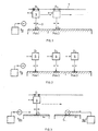
- Fig. 1 schematically shows how, in one embodiment, several ear devices or their shells are industrially manufactured in parallel processing, using laser sintering or laser- or stereolithography.
- a laser with a control unit 5 and a beam 3 is mounted above the bed 1 for powder or liquid medium.
- the laser solidifies the layer S 1 of a first ear device or of its shell while being controlled by a first individual set of data, D 1 .
- the laser is moved by a conveying device 7 into a second position where by means of the individual data set D 2 it produces the layer S 2 corresponding to a further individual contour.
- a conveying device 7 into a second position where by means of the individual data set D 2 it produces the layer S 2 corresponding to a further individual contour.
- several lasers can be moved together as one unit and accordingly more than one individual ear device can be produced simultaneously.
- sectional layers of individual ear devices or of their shells are solidified simultaneously at one or several liquid or powder beds 1 by means of simultaneously and individually controlled lasers 5.
- the powder source 9 again deposits a new layer of powder, whereas in the case of laser- or stereolithography the just solidified sectional layers or the already solidified build-ups are lowered into the liquid bed.
- the laser 5 solidifies the layer S 1 at the one powder or liquid bed 1a and then switches over to the bed 1b (dashed lines), where, during the solidification cycle at bed 1a, the powder depositing source 9b deposits powder over a previously solidified layer S 1 , or, as regards laser- or stereolithography, the layer S 1 is being lowered. Only when the laser 5 becomes active at the bed 1b the powder source 9a deposits a new layer of powder over the just solidified layer S 1 at the bed 1a, or the layer S 1 is lowered in liquid in the bed 1a.
- sectional layers of more than one ear device or of their shells are simultaneously deposited, i.e. in one stroke by one deposition head, or, when in parallel, by several such heads.
- the above discussed method allows implementing highly complex shapes of ear devices or of their shells, both as regards their external shape with individual matching to the application area and, as regards a shell, its inside shape. Overhangs, recesses and protrusions are easily implemented.
- the digitizing procedure of the individual application area is carried out in a specialized facility, in the latter case at the audiologist.
- the individual shape is recorded there - especially in relation to hearing aids - and is transmitted to a production center, be it by transmitting a data storage medium, be it by an internet connection etc.
- the ear device or its shell and specifically the in-ear hearing aid shell is shaped at the production center.
- the final assembly of the functional components is also carried out at this center.
- in-ear ear devices may be realized as hearing protectors, as earphones, as water-protection inserts and especially as in-ear hearing aids, which may be introduced similarly to rubbery plugs and of which the outer surface optimally applies the shape of the application area, namely of the auditory canal.
- venting ducts or channels can easily be fitted into the in-ear ear devices, so that as the ear device may be seated in a sealing manner in the auditory canal, eardrum ventilation is kept undegraded.
- the device's inside space can be optimized and be optimally utilized due to the individual 3D data or the application area, even individually as regards any individual apparatus configuration to be received in the device as in the case of a hearing aid.
- the centralized manufacturing of their shells allows central storing and managing of individual data relating to the individual shape of the application area and also of the individual functional components and their adjustment. If for any reason a shell must be replaced, it can be readily remanufactured by retrieving the individual data sets without the heretofore necessary laborious new matching process.
- the use of the cited additive built-up processes in manufacturing of ear devices or of their shells makes it possible to integrate thereat various functional elements which are laid out at the computer when designing the ear device and which are integrally produced as the ear device or its shell is built up.
- Conventionally such functional elements have been fitted into or joined to the finished ear device or to its shell, which may be recognized by material interfaces or by inhomogeneities in the material at link areas of such components to e.g. the shell.
- ear devices especially those provided with electronics such as hearing aids, and especially in-ear hearing aids
- components which can be directly integrated by the proposed technique into the ear device or its shell are e.g. seats and fasteners for components, earwax protection systems, venting channels or grooves for in-ear ear devices, supports which position in-ear ear devices in the auditory canal as so-called claws or channel locks.
- Fig. 4 illustrates in a schematic manner an in-ear ear device 11, e.g. an in-ear hearing aid, at which the acoustic output 13 to the ear drum is protected by an earwax protection cap 15.
- This protection cap 15 heretofore has been mounted during manufacturing as a separate part onto the shell 16 of the ear device 11, being affixed e.g. by gluing or bonding.
- the earwax protection cap 15a is directly integrated to the shell 16a of the otherwise identical in-ear ear device 11a.
- P in Fig. the link area schematically denoted by P in Fig.
- venting systems are now presented which at least partly remedy the drawbacks of known systems.
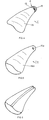
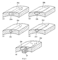
- Figs. 7(a) through (f) show schematic and perspective representations of cutaways of the outer wall 18 residing in the auditory canal of an in-ear ear device with novel venting-slot profiles.
- the cross-sectional profile of the venting slot 20a is rectangular or quadratic and constrained to predetermined, accurately maintained dimensional ratios.
- the cross-sectional profile of the venting slot 20b has the shape of the sector of a circle or of an ellipse, again constrained by accurately predetermined cross-sectional edge curve 21b.
- FIGs. 7(c) through (f) further venting slots cross-sectional profiles are shown, which additionally are protected against earwax.
- the profile of slot 20c according to fig. 7(c) is in the form of a cross-sectional T.
- the inwardly projecting parts 23c and the resulting constriction 25c pointing towards the wall of the auditory canal already provide a substantial protection against earwax influence. Even if earwax were to penetrate the constriction 25c and harden therein, the venting slot will not thereby be significantly constricted or even clogged, the slot then becomes a closed venting channel.
- the Figs. 7(d) through 7(f) are based on the principle as shown in Fig. 7(c) and the cross-sectional shape of the open slot bottom parts 27d through 27f is shown in different geometries, namely being arcuate according to Fig. 7(d) or having the form of a sector of an ellipse, triangular according to Fig. 7(e) and circular or elliptical according to Fig. 7(f).
- the most varied acoustical impedances may be implemented along the novel venting slots, which is as an example shown at the slot 29 of Fig. 8, which, propagating in its longitudinal direction, defines for different profiles, combined as desired and according to Fig. 8, from profiles according to Fig. 7.
- the resultant acoustical transfer behavior of the slot abutting the auditory canal can be computer modeled and checked and then be integrated into the in-ear ear device or its shell.
- venting slots may be differently dimensioned according to the respective application area in the auditory canal, with respect to earwax protection and to acoustical behavior and thus may be realized in an optimized manner along the surface of an ear device.
- This embodiment of the novel venting system is based on venting channels which at least along parts thereof are fully integrated into the ear device and which are thus closed there towards the wall of the auditory canals.
- This system will be elucidated below in relation to its realization in the shell of an ear device. It must be nevertheless emphasized that when no further unit needs to be integrated into an ear device and such ear device is tailored as a full material device the discussion below is also valid for channels which are provided through such full material devices.
- Fig. 11 shows in analogy to Fig. 7 different cross-sectional shapes and relations of cross-sectional areas of proposed venting channels or ducts 33a through 33e.
- the cross-sectional contour of the venting channel 33a in the shell of the ear device is rectangular or quadratic.
- the cross-section of the channel 35b has the shape of a sector of a circle or of an ellipse.
- the cross-section of the venting channel 33c is circular or elliptical, whereas it is triangular in the embodiment according to Fig. 11(d).
- the shell of the ear device exhibits a complex inside shape, for instance has an integrated support part 37.
- the venting channel 35e of this embodiment is designed with a cross-sectional contour which exploits the complex shape of the shell of the ear device. As a result its cross-sectional shape runs in a complex manner partly into the support strip 37 integrated in the shell 35e.
- Fig. 12 shows an embodiment of a fully integrated venting channel 39 which has along its length extent and as shown e.g. within the shell of the ear device, different cross-sectional shapes and/or extents of cross-sectional areas, as a result of which different acoustical impedances are implemented so as to optimize the acoustical transfer behavior.
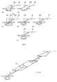
- venting channels or slots but especially closed channels as addressed in this section of the description, can easily be utilized simultaneously and at least along parts thereof as acoustical conductor segments at the output side of active electromechanical transducers, as e.g. at the output side of microphones, e.g. in in-ear hearing aids.
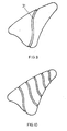
- Fig. 13 and 14 show how, on one hand, the integrated venting channels as described in this section of the description, can be extended by selecting a commensurate path along a respective ear device 43 and, on the other hand, how two or more such channels, where appropriate fitted with different and/or varying channel cross-sections, in analogy to Fig. 12, can be integrated in the ear device.
- the expert is given access to a huge number of embodiment variations of novel venting systems and in particular to a large number of degrees of freedom on account of the different parameters each dimensionable per se to individually create optimal protection against earwax and optimal acoustical transfer behavior for respective individual ear devices.
- the specific individual system configuration is calculated or computer modeled to meet the cited requirements. Thereupon the individual ear device is manufactured. Again the initially cited additive built-up processes, as known for rapid prototyping, are especially appropriate, controlled by the optimized modeling result.
- This section discloses novel ear devices optimally matching the dynamics of the sites of use, i.e. the application area.
- conventional in-ear ear devices cannot meet the requirements of the comparatively large movement dynamics of the auditory canal for instance during chewing, because they exhibit substantially the same shape stability all along the device.
- the acoustical conductors between outside-the-ear haring aids and the auditory canal cannot freely follow the movement dynamics of the application area.
- hearing protection devices with earphones, water-protection inserts etc.
- their intrinsic function, namely protection will be partly degraded when increased account is taken of the movement dynamics of the application areas.
- hearing protection devices made of elastically shape-changing plastics which meet well the cited dynamics of the application area, but as a tradeoff against their acoustical transfer behavior.
- Fig. 15 schematically shows a longitudinal section of an in-ear ear device
- Fig. 16 shows a schematic cross-section of a segment of this ear device.
- the ear device e.g. for receiving electronic components, comprises a shell 45, which is elastic, stocking-like, of thin-walled material.
- the shape stability of the shell skin, which in this embodiment is smooth on its outside, is assured, where desired, by ribs 47 integrated at the inside of the shell and being of the same material as the shell skin.
- the density and shape of ribs 47 provided will be first computed and thereupon the ear device is realized on the basis of the computed data.
- the above mentioned manufacturing processes using additive built-up are exceedingly appropriate to this purpose.
- the above discussed in-ear ear device design may be combined with a venting system as elucidated in relation with the Figs. 7 through 14.
- the ribs controlling dimensional or shape stability as e.g. bending behavior in given zones of the ear device may be fitted with different cross-sectional contours, and may transit where necessary from one contour into another as propagating along their longitudinal extent.
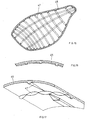
- Fig. 17 is a perspective view schematically illustrating the design of the outer skin 45 fitted with ribs 47 of varying cross-sectional areas along their longitudinal extents.
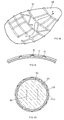
- the inner rib pattern can be complemented as shown in Figs. 17 and 18 by an external rib pattern.
- a pattern of ribs 51 is manufactured on the outside of the ear device 49, where called for, with zones of varying density, direction and cross-sectional profile.
- ear devices with a cavity such complementation may be implemented in ear devices with a cavity, but also in ear devices lacking such cavities, which do not hold e.g. electronic components, namely e.g. in hearing protection and in water protection ear devices.
- Such an ear device is shown in a schematic cross-sectional view in Fig. 20.
- the inside space 53 consists of an extremely compressible absorbing material which is enclosed by a shape-subtending shell skin 55 which is provided with the rib pattern 57.
- Both the "skin" 55 and the rib pattern 57 are jointly and integrally manufactured. Again the initially cited manufacturing processes are appropriate for this purpose, with resort to additive built-up techniques.
- Figs. 18 and 19 in particular show that by means of the external rib pattern, it is possible to simultaneously form venting slots or free venting spaces as indicated in schematic and illustrative manner by the arrow P.
- ear devices also can be manufactured which leave free a cavity to receive units such as electronic components, but wherein the intermediate space between such a cavity 59 designed specifically for the required volumes and shapes of the additional elements to be integrated and the shell skin 55 is filled by e.g. a resilient or acoustically attenuating material, or wherein components to be installed are cast in place with such a material up to the shell skin 55.
- the shell 55 or 45 of the Figs. 15, 16 and 17 furthermore may be made of an electrically conducting material so that thereby the electronic components inside become electrically shielded. This feature also applies to the filling material 53 of Fig. 20.
- an ear device was shown by the example of a in-ear ear device, the shell thereof being shape stabilized by inner and/or outer ribs, resulting in an extremely lightweight and controllably shapable construction. Obviously, such construction may also be applied as required to outside-the-ear ear devices.
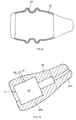
- Fig. 21 shows another embodiment of an-ear ear device which is made flextural or compressible in a predetermined region.
- the shell 51 of the ear device in particular that of an in-ear hearing aid, for that purpose, is fitted in one or more predetermined areas with a corrugated or accordion-like bellows structure 63, where bendability or compressability are required.
- this procedure is illustrated in Fig. 21 by means of the shell of an in-ear ear device, such a structure can be implemented easily and if required also for an outside-the-ear ear device.
- the initially cited manufacturing processes are preferably used for implementation.
- this ear device can be filled too with a filler material corresponding to the particular requirements, or components installed therein can be embedded in such a filler material, as a result of which the device becomes more stable and has improved acoustical behavior.
- Fig. 22 schematically shows an in-ear ear device 65 in longitudinal section, the shape of the inside space 67 substantially corresponding to that of the electronic module 69 of Fig. 23 to be received in this inside space.
- the ear device 65 is made of an elastic material, and as shown in Fig. 23, can be urged over the electronic module 69.
- the inside space 67 is configured in such a way that the module(s) to be received are directly positioned and affixed in mechanically interlocking manner by the ear device 65. On account of such a procedure, it is easy to fit one and the same electronic module 69 with different ear devices 65 so as e.g. to account for the growth of the auditory canal of a child.
- the ear device shell becomes so practically an easily exchangeable, disposable accessory part.
- the ear device 65 is easily exchanged not only to match changed conditions on the application area, but also merely for being soiled. This feature even can be used for instance in the event of external otitis, in medical applications, for instance to deposit medicines at the outer surface of the ear device or at least to insert sterilized ear devices at regular intervals.
- the design shown in the Figs. 22 and 23 may be combined with a design disclosed in the sections 2) and 3), and preferably the ear device 65 is manufactured by the processes discussed under section 1), thereby allowing configuring the most complex shapes to seat the module 69 without play and vibration-free.
- the phase plate 1 which otherwise is present in conventional in-ear hearing aids, is made integrally with the ear device.
- the same feature applies to further supports and to seats for the electronic components of the hearing aid.
- This feature also applies to the ear devices as discussed in sections 2) and 3) and as discussed in the following sections 5), 6) and 7).
- Fig. 24 shows a further embodiment of an ear device, again in the form of an in-ear hearing aid as an example, allowing simple and quick exchange of installed components.
- the design consists in manufacturing the ear device shell of an in-ear ear device subdivided into several parts, which may be assembled in the manner as e.g. shown in Fig. 24.
- quick connections such as latches, pawl locks or even bayonet locks or the like
- the housing or shell segments 73a and 73b of the in-ear ear device can quickly be mutually separated, the installed components such as electronic modules can be removed and may be inserted in another shell possibly with a different outer shape or principally in a new shell if this is necessary, for instance for cleaning or sterility reasons.
- This goal is principally attained in that the acoustical conductors mentioned - at the input side of the acoustic/electrical converters or at the output side of the electrical to acoustical converters - are integrated into the ear device or in the wall of the ear device shell.
- a converter module 75 comprises an acoustical input or output 77.
- the shell 79 of the ear device of an in-ear or of an outside-the-ear hearing aid or of a headphone comprises, as an integral part, an acoustical conductor 81.
- This acoustical conductor is embedded at least to a part and as shown in Fig. 25 within the wall of the ear device shell 79.
- acoustical stub conductors or conductor segments 83 preferably the respective acoustical impedance of the acoustical conductor 81 is matched.
- this concept makes it possible to implement acoustical input apertures 85 distributed along the ear device and there where desired, and to couple such apertures via acoustical conductors 89, which are integrated in the ear device or its shell 87 to the acoustical/electrical converters 91 as provided and essentially independent therefrom, where such converters 91 are placed within the ear device.
- acoustical conductors 89 which are integrated in the ear device or its shell 87 to the acoustical/electrical converters 91 as provided and essentially independent therefrom, where such converters 91 are placed within the ear device.
- Fig. 26 there is e.g. shown how two converters are centralized to one module and their inputs are connected to the desired apertures 85 by acoustical conductors 89 respectively tailored. From consideration of the Figs.
- venting channels additionally as acoustical conductor channels, especially if one accurately conceives the acoustical impedance conditions by means of acoustical matching members 83 as schematically shown in Fig. 25.
- each finished ear device in particular in-ear ear devices
- each finished ear device thereby especially each in-ear ear device and thereby most particularly each in-ear hearing aid. Therefore it is proposed to provide within the ear device or within its shell an individual identification by means of intrusions and/or extrusions which besides of the individual purchaser may identify e.g. the manufacturer, may further define for a serial number of the product, may identify whether the device is to be worn on the left or on the right hand side.
- Such an identification is implemented most preferably during the manufacturing of the ear device with the built-up processes as were described under section 1). By such identification it is made sure that departing from manufacturing any mix up of devices is prevented. This is especially important for a subsequent possibly automated assembly with further modules, so e.g. during assembling of in-ear hearing aids. This procedure may obviously be combined with one or more than one of the procedures and aspects as described under the sections 2) to 5).
- a further possibility e.g. resides to register the dynamics of the application area by means of x-rays.
- the computer unit 97 calculates from the dynamic data as stored in unit 95 and possibly with the help of further manufacturing parameters as schematically shown at K the best fitting shape for the ear device so that an optimum comfort is reached when wearing the device in daily use and thereby maintaining its functional task.
- the computer unit 97 calculates the characteristics of the different areas of the ear device with respect to flexibility, flexural behavior, compressability etc. At its output the computer unit 97 controls as was mentioned the manufacturing process 99, thereby preferably a manufacturing process as it was disclosed in section 1) as preferred manufacturing processes.
- module housings When applying a hearing device to an individual's ear 79, being for an in-the-ear hearing device into the ear channel of the individual or for an outside-the-ear hearing device adjacent to individual's ear, characteristics of individual's skin at such application area should, under certain circumstances, be considered when manufacturing the hearing device for that individual.
- a single or multiple characteristics (a) to (d) of the skin at the application area of the individual i.e. at that area, which comes in contact with the hearing device carried by the individual and possibly of areas just adjacent thereto, may be considered to make sure that the applied hearing device does not act as a disturbing factor for the individual under any of the addressed aspects.
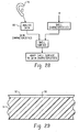
- the skin at that area is analyzed. This may be done by visual inspection, taking a probe etc. briefly by any known method of skin analysis. Thereby there is generated a skin analyzing result, which is significant for at least one of the following skin characteristics:
- Information of one and preferably more than one of the above mentioned skin characteristics is retrieved from skin analyzing 80 and applied for controlling surface manufacturing of the hearing device shell, especially along areas of said surface, which will be situated adjacent to or in intimate contact with individual's skin at the application area.
- Manufacturing of the shell besides of such surface manufacturing is governed by other criteria P, as by geometric shape of the application area, intended use of the hearing device, modules to be built in etc.
- the surface area of the hearing device shell is manufactured to take into account visual appearance and possibly macro- and/or micro-roughness and texture of the skin by appropriately coloring and appropriately tailoring surface macro- and/or micro-roughness of the shell's surface area. This may be done by appropriately manufacturing such surface of the shell material, i.e. by appropriately tailoring its substantial rigid material surface.
- the surface of the shell to come in intimate contact with the application area's skin of the individual by applying a gel, a liquid or a pasteous substance to the surface of the shell.
- a substance as an antibiotically acting substance or a neutralizing substance, may thereby be applied to the substantially rigid material of the remaining shell in that, as shown in fig. 29 the solid material surface 90 of the shell 91 is roughened or structured, especially micro-structured, and there is applied a film 92 of the said liquid, gel or pasteous material.
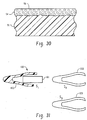
- An other possibility is, as shown in fig. 30, to conceive at least the surface area of the solid shell material 30 to be porous and to fill such porous surface 94 with the respectively suited liquid, gel or pasteous substance to be slowly dispatched to the surface 96 of the shell 91 so as to realize long-term dispatching such substance to the skin of individual's application area.
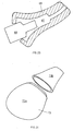
- a hearing device 100 schematically shown, some parts or modules 101 upon which a shell 103 is removably applied as e.g. a stocking.
- a shell 103 is removably applied as e.g. a stocking.
- the hearing device may become a device for dispatching medicaments to the individual, especially via the skin of individual's application area.
- the shell's surface especially at the contact area to individual's application area, any disturbing of the skin as of irritation thereof may be prevented in advance.
Landscapes
- Engineering & Computer Science (AREA)
- Physics & Mathematics (AREA)
- Manufacturing & Machinery (AREA)
- Health & Medical Sciences (AREA)
- Materials Engineering (AREA)
- Chemical & Material Sciences (AREA)
- General Health & Medical Sciences (AREA)
- Acoustics & Sound (AREA)
- Otolaryngology (AREA)
- Optics & Photonics (AREA)
- Neurosurgery (AREA)
- Life Sciences & Earth Sciences (AREA)
- Signal Processing (AREA)
- Mechanical Engineering (AREA)
- Public Health (AREA)
- Biomedical Technology (AREA)
- Veterinary Medicine (AREA)
- Vascular Medicine (AREA)
- Psychology (AREA)
- Biophysics (AREA)
- Heart & Thoracic Surgery (AREA)
- Animal Behavior & Ethology (AREA)
- Headphones And Earphones (AREA)
- Measurement Of The Respiration, Hearing Ability, Form, And Blood Characteristics Of Living Organisms (AREA)
Applications Claiming Priority (2)
| Application Number | Priority Date | Filing Date | Title |
|---|---|---|---|
| US09/982,290 US7014010B2 (en) | 2000-06-30 | 2001-10-17 | Method for manufacturing an ear device and ear device |
| US982290 | 2001-10-17 |
Publications (2)
| Publication Number | Publication Date |
|---|---|
| EP1320280A2 true EP1320280A2 (fr) | 2003-06-18 |
| EP1320280A3 EP1320280A3 (fr) | 2003-08-13 |
Family
ID=25529008
Family Applications (1)
| Application Number | Title | Priority Date | Filing Date |
|---|---|---|---|
| EP02016677A Withdrawn EP1320280A3 (fr) | 2001-10-17 | 2002-07-26 | Procédé de fabrication d'appareils auditifs |
Country Status (6)
| Country | Link |
|---|---|
| US (2) | US7014010B2 (fr) |
| EP (1) | EP1320280A3 (fr) |
| JP (3) | JP4674032B2 (fr) |
| AU (1) | AU2002300247B2 (fr) |
| CA (1) | CA2397245A1 (fr) |
| WO (1) | WO2003034783A2 (fr) |
Cited By (4)
| Publication number | Priority date | Publication date | Assignee | Title |
|---|---|---|---|---|
| EP1585361A1 (fr) * | 2004-03-31 | 2005-10-12 | Siemens Audiologische Technik GmbH | Casque d'écoute avec fonctionnalité de prothèse auditive |
| EP1562399A3 (fr) * | 2005-03-24 | 2005-10-19 | Phonak Ag | Paire de prothèses auditives avec identification droite-gauche pour non-voyants |
| EP1595515A1 (fr) * | 2004-05-10 | 2005-11-16 | Phonak Ag | Bouchon d'oreille, procédé de fabrication et utilisation |
| US8616214B2 (en) | 2011-04-06 | 2013-12-31 | Kimberly-Clark Worldwide, Inc. | Earplug having a resilient core structure |
Families Citing this family (23)
| Publication number | Priority date | Publication date | Assignee | Title |
|---|---|---|---|---|
| US7555356B2 (en) * | 2003-04-03 | 2009-06-30 | Phonak Ag | Method for manufacturing a body-worn electronic device adapted to the shape of an individual's body area |
| US20050074543A1 (en) * | 2003-10-07 | 2005-04-07 | Stevens Randal A. | Method of coating an SLA part |
| JP2005131050A (ja) * | 2003-10-29 | 2005-05-26 | Matsushita Electric Ind Co Ltd | 外耳道形状の測定方法及び補聴器シェルの製造方法並びに補聴器 |
| CA2613507C (fr) * | 2005-06-27 | 2011-03-15 | Widex A/S | Methode et outil de mise en forme d'une piece allongee deformable destinee a une prothese auditive |
| US20070147642A1 (en) * | 2005-12-22 | 2007-06-28 | Siemens Audiologische Technik Gmbh | Method for constructing an otoplastic and calibrating a hearing device |
| US7740104B1 (en) * | 2006-01-11 | 2010-06-22 | Red Tail Hawk Corporation | Multiple resonator attenuating earplug |
| JP2008236147A (ja) * | 2007-03-19 | 2008-10-02 | Rion Co Ltd | 耳穴形補聴器の製造方法 |
| US8384916B2 (en) | 2008-07-24 | 2013-02-26 | Massachusetts Institute Of Technology | Dynamic three-dimensional imaging of ear canals |
| JP2010161765A (ja) * | 2008-12-09 | 2010-07-22 | Gn Resound Japan Kk | 耳あな式補聴器 |
| JP5305888B2 (ja) * | 2008-12-19 | 2013-10-02 | リオン株式会社 | 耳あな型補聴器 |
| WO2011000375A1 (fr) * | 2009-07-02 | 2011-01-06 | Widex A/S | Bouchon d'oreille à électrodes de surface |
| EP4353479B1 (fr) | 2009-08-19 | 2026-03-11 | Smith & Nephew, Inc. | Structures d'implant poreux |
| JP2011082701A (ja) * | 2009-10-05 | 2011-04-21 | Foster Electric Co Ltd | ヘッドホン |
| US9512627B2 (en) | 2010-05-10 | 2016-12-06 | L. Michael Taron | Collapsible saw horse |
| US9042589B2 (en) * | 2013-10-24 | 2015-05-26 | Logitech Europe, S.A. | Custom fit in-ear monitors utilizing a single piece driver module |
| KR101545087B1 (ko) * | 2014-04-17 | 2015-08-17 | 채승호 | 귀마개와 이를 가지는 귀마개 세트 |
| CA2983197C (fr) | 2015-05-04 | 2020-06-30 | T&W Engineering A/S | Moniteur d'eeg pourvu d'un boitier fixe individuellement sur une personne |
| EP3957079A1 (fr) * | 2019-06-12 | 2022-02-23 | Huawei Technologies Co., Ltd. | Écouteur ayant un agencement de ventilation |
| EP4054203A4 (fr) * | 2019-10-30 | 2024-01-17 | Listeningassist Corporation | Équipement destiné à être porté sur l'oreille externe |
| WO2021123048A1 (fr) * | 2019-12-19 | 2021-06-24 | Gn Hearing A/S | Manchon d'étanchéité pour la protection de composants dans un dispositif auditif |
| US11425479B2 (en) | 2020-05-26 | 2022-08-23 | Logitech Europe S.A. | In-ear audio device with interchangeable faceplate |
| KR102292926B1 (ko) * | 2020-08-27 | 2021-08-25 | 주식회사 알머스 | 이어폰용 가변 이어팁 |
| JP7755782B2 (ja) * | 2021-10-29 | 2025-10-17 | 株式会社Jvcケンウッド | 耳装着具 |
Citations (7)
| Publication number | Priority date | Publication date | Assignee | Title |
|---|---|---|---|---|
| DE1231304B (de) * | 1964-12-24 | 1966-12-29 | Wolfgang Dreve | Verfahren zur Herstellung von Ohrpassstuecken fuer Schwerhoerigen-Geraete und Plastik zur Durch-fuehrung des Verfahrens |
| EP0084973A2 (fr) * | 1982-01-25 | 1983-08-03 | Nicolet Instrument Corporation | Electrode pour le canal auditif |
| DE9102655U1 (de) * | 1990-10-10 | 1991-07-18 | Dreve, Wolfgang, 4750 Unna | Otoplastik-Hörgerät |
| US5889874A (en) * | 1997-02-18 | 1999-03-30 | Siemens Audiologische Technik Gmbh | Hearing aid device to be worn in the ear |
| WO2000076271A1 (fr) * | 1999-06-08 | 2000-12-14 | Insonus Medical, Inc. | Dispositif de correction auditive a installation dans le conduit, pour un port prolonge |
| FR2806630A1 (fr) * | 2000-03-22 | 2001-09-28 | Iris Laboratoire | Element de prothese implantable dans le corps |
| WO2001087001A2 (fr) * | 2001-07-26 | 2001-11-15 | Phonak Ag | Procede de fabrication de dispositifs d'ecoute |
Family Cites Families (22)
| Publication number | Priority date | Publication date | Assignee | Title |
|---|---|---|---|---|
| US3996934A (en) * | 1971-08-09 | 1976-12-14 | Alza Corporation | Medical bandage |
| US4194512A (en) * | 1977-06-08 | 1980-03-25 | Foti Thomas M | Probe for nystagmus testing |
| DE8518681U1 (de) * | 1985-06-27 | 1986-06-12 | Siemens AG, 1000 Berlin und 8000 München | Hörhilfe |
| US5068902A (en) * | 1986-11-13 | 1991-11-26 | Epic Corporation | Method and apparatus for reducing acoustical distortion |
| US4817609A (en) * | 1987-09-11 | 1989-04-04 | Resound Corporation | Method for treating hearing deficiencies |
| US4820525A (en) * | 1987-09-17 | 1989-04-11 | American Home Products Corporation (Del.) | Transdermal drug delivery system |
| CH677570A5 (fr) * | 1989-05-17 | 1991-05-31 | Ascom Audiosys Ag | |
| JP2571128B2 (ja) * | 1989-06-16 | 1997-01-16 | フオスター電機株式会社 | ヘッドホン |
| US5045266A (en) * | 1989-11-02 | 1991-09-03 | National Patent Development Corporation | Process of making a hearing aid earmold in situ |
| US5185802A (en) * | 1990-04-12 | 1993-02-09 | Beltone Electronics Corporation | Modular hearing aid system |
| DE4041105A1 (de) | 1990-12-21 | 1992-06-25 | Toepholm & Westermann | Verfahren zum herstellen von individuell an die konturen eines ohrkanals angepassten otoplastiken oder ohrpassstuecken |
| US5487012A (en) | 1990-12-21 | 1996-01-23 | Topholm & Westermann Aps | Method of preparing an otoplasty or adaptive earpiece individually matched to the shape of an auditory canal |
| AU6439896A (en) * | 1995-09-14 | 1997-03-20 | Resound Corporation | Method for fabricating a hearing aid faceplate and a faceplate produced thereby |
| JP2837649B2 (ja) * | 1995-10-04 | 1998-12-16 | リオン株式会社 | 挿耳形補聴器用シェルの製造方法 |
| BE1010200A3 (nl) | 1996-04-26 | 1998-03-03 | Variphone Benelux Naamloze Ven | Werkwijze en inrichting voor het vervaardigen van oorstukjes. |
| AR012683A1 (es) * | 1997-07-29 | 2000-11-08 | Decibel Instr Inc | Un acoplador acustico intracanal, el adaptador acustico intracanal que lo contiene y un dispositivo de distribucion de acopladores que lo contiene |
| JPH1169497A (ja) * | 1997-08-18 | 1999-03-09 | Shizuko Honda | 補聴器保護カバ− |
| WO2000034739A2 (fr) | 1998-12-10 | 2000-06-15 | William Forrest Fagan | Procede de fabrication d'enveloppes d'appareils de correction auditive |
| US6940989B1 (en) * | 1999-12-30 | 2005-09-06 | Insound Medical, Inc. | Direct tympanic drive via a floating filament assembly |
| DE50010130D1 (de) | 2000-06-30 | 2005-05-25 | Phonak Ag Staefa | Verfahren zur herstellung von im-ohr-hörgeräten und im-ohr-hörgerät |
| US20020133080A1 (en) * | 2001-02-06 | 2002-09-19 | William Apruzzese | Layered calibration standard for tissue sampling |
| US20030100819A1 (en) * | 2001-11-28 | 2003-05-29 | Welch Allyn, Inc. | Hand-held chemical sensing instrument |
-
2001
- 2001-10-17 US US09/982,290 patent/US7014010B2/en not_active Expired - Lifetime
- 2001-11-30 WO PCT/CH2001/000690 patent/WO2003034783A2/fr not_active Ceased
-
2002
- 2002-07-23 AU AU2002300247A patent/AU2002300247B2/en not_active Ceased
- 2002-07-26 EP EP02016677A patent/EP1320280A3/fr not_active Withdrawn
- 2002-08-09 CA CA002397245A patent/CA2397245A1/fr not_active Abandoned
- 2002-10-09 JP JP2002295769A patent/JP4674032B2/ja not_active Expired - Fee Related
-
2003
- 2003-12-11 US US10/733,063 patent/US7185733B2/en not_active Expired - Lifetime
-
2009
- 2009-02-20 JP JP2009037814A patent/JP2009105994A/ja active Pending
-
2010
- 2010-12-10 JP JP2010276112A patent/JP2011087322A/ja active Pending
Patent Citations (7)
| Publication number | Priority date | Publication date | Assignee | Title |
|---|---|---|---|---|
| DE1231304B (de) * | 1964-12-24 | 1966-12-29 | Wolfgang Dreve | Verfahren zur Herstellung von Ohrpassstuecken fuer Schwerhoerigen-Geraete und Plastik zur Durch-fuehrung des Verfahrens |
| EP0084973A2 (fr) * | 1982-01-25 | 1983-08-03 | Nicolet Instrument Corporation | Electrode pour le canal auditif |
| DE9102655U1 (de) * | 1990-10-10 | 1991-07-18 | Dreve, Wolfgang, 4750 Unna | Otoplastik-Hörgerät |
| US5889874A (en) * | 1997-02-18 | 1999-03-30 | Siemens Audiologische Technik Gmbh | Hearing aid device to be worn in the ear |
| WO2000076271A1 (fr) * | 1999-06-08 | 2000-12-14 | Insonus Medical, Inc. | Dispositif de correction auditive a installation dans le conduit, pour un port prolonge |
| FR2806630A1 (fr) * | 2000-03-22 | 2001-09-28 | Iris Laboratoire | Element de prothese implantable dans le corps |
| WO2001087001A2 (fr) * | 2001-07-26 | 2001-11-15 | Phonak Ag | Procede de fabrication de dispositifs d'ecoute |
Non-Patent Citations (2)
| Title |
|---|
| DATABASE MEDLINE [online] US NATIONAL LIBRARY OF MEDICINE (NLM), BETHESDA, MD, US; 1 January 1992 (1992-01-01), MEDING B, RINGDAHL A: "Allergic contact dermatitis from the earmolds of hearing aids", Database accession no. 1601193 * |
| MEDING, BIRGITTA; RINGDAHL, ANDERS: "Allergic Contact Dermatitis from the Earmolds of Hearing Aids.", EAR & HEARING, vol. 13, no. 2, 1 April 1992 (1992-04-01), pages 122 - 124 * |
Cited By (4)
| Publication number | Priority date | Publication date | Assignee | Title |
|---|---|---|---|---|
| EP1585361A1 (fr) * | 2004-03-31 | 2005-10-12 | Siemens Audiologische Technik GmbH | Casque d'écoute avec fonctionnalité de prothèse auditive |
| EP1595515A1 (fr) * | 2004-05-10 | 2005-11-16 | Phonak Ag | Bouchon d'oreille, procédé de fabrication et utilisation |
| EP1562399A3 (fr) * | 2005-03-24 | 2005-10-19 | Phonak Ag | Paire de prothèses auditives avec identification droite-gauche pour non-voyants |
| US8616214B2 (en) | 2011-04-06 | 2013-12-31 | Kimberly-Clark Worldwide, Inc. | Earplug having a resilient core structure |
Also Published As
| Publication number | Publication date |
|---|---|
| AU2002300247B2 (en) | 2007-12-20 |
| JP2011087322A (ja) | 2011-04-28 |
| WO2003034783A3 (fr) | 2003-10-09 |
| US20040120978A1 (en) | 2004-06-24 |
| CA2397245A1 (fr) | 2003-04-17 |
| JP2003189397A (ja) | 2003-07-04 |
| US7185733B2 (en) | 2007-03-06 |
| US20040069560A1 (en) | 2004-04-15 |
| US7014010B2 (en) | 2006-03-21 |
| JP4674032B2 (ja) | 2011-04-20 |
| WO2003034783A2 (fr) | 2003-04-24 |
| EP1320280A3 (fr) | 2003-08-13 |
| JP2009105994A (ja) | 2009-05-14 |
Similar Documents
| Publication | Publication Date | Title |
|---|---|---|
| US7014010B2 (en) | Method for manufacturing an ear device and ear device | |
| US6540045B1 (en) | Method for manufacturing an ear device and ear device | |
| AU2000272654B2 (en) | Method and Apparatus for Manufacturing an Ear Device Shell | |
| CA2410995C (fr) | Otoplastique et procede de fabrication d'un otoplastique | |
| US7387187B2 (en) | Custom-molded ear-plug, and process for producing a custom-molded ear-plug device | |
| US7394909B1 (en) | Hearing device with embedded channnel | |
| US6595317B1 (en) | Custom-moulded ear-plug device | |
| US6401859B1 (en) | Custom-molded ear-plug, and process for producing a custom-molded ear-plug device | |
| CA2422425C (fr) | Prothese auditive | |
| AU2000272655B2 (en) | Ear Device Shells | |
| AU2008201247B2 (en) | Apparatus and Method for Applying a Substance to a Human Body | |
| AU2000272659B2 (en) | Method for Manufacturing a Customized Hearing Device | |
| AU2000272657B2 (en) | Otoplastic | |
| CA2419950C (fr) | Otoplastique avec module integre, otoplastique place dans l'oreille et procede d'adaptation des otoplastiques |
Legal Events
| Date | Code | Title | Description |
|---|---|---|---|
| PUAI | Public reference made under article 153(3) epc to a published international application that has entered the european phase |
Free format text: ORIGINAL CODE: 0009012 |
|
| AK | Designated contracting states |
Designated state(s): AT BE BG CH CY CZ DE DK EE ES FI FR GB GR IE IT LI LU MC NL PT SE SK TR |
|
| AX | Request for extension of the european patent |
Extension state: AL LT LV MK RO SI |
|
| PUAL | Search report despatched |
Free format text: ORIGINAL CODE: 0009013 |
|
| AK | Designated contracting states |
Designated state(s): AT BE BG CH CY CZ DE DK EE ES FI FR GB GR IE IT LI LU MC NL PT SE SK TR |
|
| AX | Request for extension of the european patent |
Extension state: AL LT LV MK RO SI |
|
| 17P | Request for examination filed |
Effective date: 20040117 |
|
| AKX | Designation fees paid |
Designated state(s): CH DE DK FR GB LI |
|
| RAP1 | Party data changed (applicant data changed or rights of an application transferred) |
Owner name: SONOVA AG |
|
| 17Q | First examination report despatched |
Effective date: 20151001 |
|
| STAA | Information on the status of an ep patent application or granted ep patent |
Free format text: STATUS: THE APPLICATION IS DEEMED TO BE WITHDRAWN |
|
| 18D | Application deemed to be withdrawn |
Effective date: 20171122 |
|
| RIC1 | Information provided on ipc code assigned before grant |
Ipc: H04R 25/00 20060101AFI20030429BHEP |