EP1320307B1 - Sonnenschirm mit heizvorrichtung - Google Patents
Sonnenschirm mit heizvorrichtung Download PDFInfo
- Publication number
- EP1320307B1 EP1320307B1 EP01975021A EP01975021A EP1320307B1 EP 1320307 B1 EP1320307 B1 EP 1320307B1 EP 01975021 A EP01975021 A EP 01975021A EP 01975021 A EP01975021 A EP 01975021A EP 1320307 B1 EP1320307 B1 EP 1320307B1
- Authority
- EP
- European Patent Office
- Prior art keywords
- parasol
- column
- heating device
- canopy
- heater
- Prior art date
- Legal status (The legal status is an assumption and is not a legal conclusion. Google has not performed a legal analysis and makes no representation as to the accuracy of the status listed.)
- Expired - Lifetime
Links
- 238000010438 heat treatment Methods 0.000 title claims abstract description 29
- 230000002093 peripheral effect Effects 0.000 claims description 2
- 238000004804 winding Methods 0.000 claims description 2
- 238000006073 displacement reaction Methods 0.000 description 2
- 230000002349 favourable effect Effects 0.000 description 2
- 238000013021 overheating Methods 0.000 description 2
- 229910000990 Ni alloy Inorganic materials 0.000 description 1
- 230000001627 detrimental effect Effects 0.000 description 1
- 238000005485 electric heating Methods 0.000 description 1
- 230000005611 electricity Effects 0.000 description 1
- 239000004744 fabric Substances 0.000 description 1
- 239000007788 liquid Substances 0.000 description 1
- 239000000463 material Substances 0.000 description 1
- 239000011490 mineral wool Substances 0.000 description 1
- 229920000728 polyester Polymers 0.000 description 1
- 230000005855 radiation Effects 0.000 description 1
- 239000005871 repellent Substances 0.000 description 1
Images


Classifications
-
- A—HUMAN NECESSITIES
- A45—HAND OR TRAVELLING ARTICLES
- A45B—WALKING STICKS; UMBRELLAS; LADIES' OR LIKE FANS
- A45B3/00—Sticks combined with other objects
Definitions
- the invention relates to a parasol comprising a column which is provided with a base and has attached thereto a collapsible canopy, provided with a heating device mounted on the column.
- a patio umbrella with a column fixed in a dining table, provided with a radiant heater for patio heating fixed in the column.
- the radiant heater in the known patio parasol is provided with a chimney on its upper side which extends through an opening in the top of the canopy.
- the canopy is stiffened by ribs which are pivotally attached to a hood over the heater.
- the heating device is displaceable along the column between a lowest position in state of rest, wherein the canopy is collapsed, and a highest position in operating state, wherein the canopy is opened out.
- the heating device is manually displaceable along the column.
- the parasol is preferably provided with displacing means for displacing the heating device.
- the displacing means comprise a rotatable screw spindle which extends parallel to the column and which is mounted on its underside on the column and screwed into a spindle nut rigidly coupled to the heating device.
- the displacing means comprise telescopic elements extending round the column.
- the displacing means comprise a cable which is trained over a pulley at the top of the column and which is connected on its one end to the heating device and on its other end to a winding device which is connected to the column and which can be locked for instance with a ratchet.
- the displacing means comprise a drive motor.
- the heating device in a parasol according to the invention is optionally an electric heating element or a gas or petrol or oil heater, and will therefore be provided with respectively a flexible electricity cable or a flexible gas or liquid conduit.
- the column is therefore provided at least partially with a slot in longitudinal direction for receiving a flexible conduit in the column.
- the invention provides particular advantage in an embodiment in which the base comprises a housing for receiving the heating device in the state of rest.
- the base comprises in a favourable embodiment a housing for receiving a gas tank.
- a parasol according to the invention is preferably provided with switching means for switching off the heating device when the parasol is collapsed, so as to prevent unsafe situations in the case of improper use.
- the parasol is provided with locking means for locking the canopy in the operating state of the heating device.
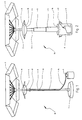
- Fig. 1 shows a parasol 10 with a canopy 3 of a usual type on a column 2 which is inserted into a base 1.
- a gas heater 4 which is slidable round column 2 and which is provided with gas from a gas tank 9 from which a conduit 14 is carried along column 2 to heater 4.
- Heater 4 is locked with a pin 12 which protrudes through a transverse bore 13 in column 2. Since a plurality of transverse bores 13 are arranged in column 2, the height of heater 4 is adjustable.
- Column 2 passes through a central opening in heater 4, wherein the cross-section of this opening is larger than that of column 2, so that a substantially free space is formed between heater 4 and column 2, thus preventing column 2 from becoming overheated.
- Canopy 3 is manufactured from a strongly water-repellent material, for instance a 100% polyester cloth, which is protected from excessively high temperatures of heater 4 by a hood 11 over heater 4.
- Fig. 2 shows a parasol 20 with a column 2 which is inserted into a base which forms the housing 8 (shown cut-away) for a gas tank 9.
- Heater 4 is mounted on the top side of a number of telescopic elements 5 which extend round column 2.
- the telescopic elements 5 are telescoped, and heater 9 rests with its concave-shaped underside 15 in a corresponding convex-shaped upper part 16 of housing 8, and the gas conduit (not shown) between tank 9 and heater 4, which in the operating state extends through hollow column 2, is accommodated wholly in housing 8.
- the housing 8 is provided with handles 17.
- Fig. 3 shows a parasol 30 with a column 2 which is inserted into a base which forms the housing 8 (shown cut-away) for a gas tank 9.
- Heater 4 is displaceable along column 2 by means of a cable (not shown) which is trained over a pulley (not shown) at the top of column 2 and which is connected at its one end to heater 4 and at its other end to a hand winch 6 with ratchet connected to column 2.
- a longitudinal slot 7 in column 2 enables the gas conduit to be carried between heater 4 and gas tank 9 through the interior of the column at any height of heater 4, wherein housing 8 provides sufficient space to accommodate the gas conduit in the state of rest, wherein heater 4 rests with its convex-shaped underside 15 in the correspondingly formed concave-shaped upper part 16 of housing 8.
- the housing 8 is provided with wheels 18.
- Fig. 4 shows a part of a column 2 to which respectively a gas heater 4 and a heater hood 11 are mounted using slippers 19.
- Gas heater 4 takes the form of a flat cylinder with upper surface 21, a lower surface 22 provided with a gas connection 25 and a perforated outer cylinder casing 23, around which a web 24 of a nickel alloy is wrapped by way of glow body.
- an opening is formed in the centre, this opening being bounded by an inner cylinder casing 26 which extends above and below heater 4 and which has a diameter which is greater than that of column 2 and is provided above and below heater 4 with a reflecting surface on its outside to prevent overheating of the column by the heater.
- a hood 11 is fixed on column 2, likewise with slippers 19 on an inner cylinder casing 27 which extends above and below hood 11 and which has a diameter which is greater than that of column 2 and is provided with a reflecting surface above and below hood 11 on its outside, wherein cylinder casing 27 is bounded on the side directed toward heater 4 by a non-convex, in this case flat central surface 29 and a convex peripheral paraboloid 31.
- the flat surface 29 protects the parasol (not shown) above hood 11 and particularly the column 2 against overheating, the paraboloid 31 reflects the infrared radiation emitted by the glow covering 24 of gas heater 4 in downward direction in an annular beam, the width of which is determined by the distance between heater 4 and hood 11 and by the height of both relative to the base of the column.
- Hood 11 further comprises an insulating layer 28, for instance of rockwool, which is enclosed between the lower surface 29, 31 and an upper surface 32.
Landscapes
- Catching Or Destruction (AREA)
- Electric Ovens (AREA)
- Central Heating Systems (AREA)
- Gas Burners (AREA)
Claims (15)
- Sonnenschirm (10, 20, 30), der einen mit einem Fuß (1, 8) versehenen Mast (2) und ein daran befestigtes faltbares Schirmdach (3) umfasst, und der mit einer an dem Mast (2) befestigten Heizvorrichtung (4) versehen ist, dadurch gekennzeichnet, dass die Heizvorrichtung (4) entlang dem Mast (2) zwischen einem niedrigsten Stand in Ruhelage, wobei das Schirmdach (3) zusammengefaltet ist, und einem höchsten Stand in Betriebszustand, wobei das Schirmdach (3) geöffnet ist, verstellbar ist.
- Sonnenschirm (10, 20, 30) nach Anspruch 1, dadurch gekennzeichnet, dass er mit Verstellmitteln (5, 6) zum Verstellen der Heizvorrichtung (4) versehen ist.
- Sonnenschirm nach Anspruch 2, dadurch gekennzeichnet, dass die Verstellmittel eine drehbare Schraubenspindel umfassen, die sich parallel zu dem Mast erstreckt und die an ihrer Unterseite an dem Mast befestigt und in eine starr mit der Heizvorrichtung gekoppelten Spindelmutter geschraubt ist.
- Sonnenschirm (20) nach Anspruch 2, dadurch gekennzeichnet, dass die Verstellmittel sich um den Mast (2) erstreckende Teleskopelemente (5) umfassen.
- Sonnenschirm (30) nach Anspruch 2, dadurch gekennzeichnet, dass die Verstellmittel ein Seil umfassen, das über eine Seilscheibe an der Oberseite des Mastes (2) geführt wird und das an seinem einen Ende mit der Heizvorrichtung (4) und an seinem anderen Ende mit einer mit dem Mast (2) verbundenen Aufwickelvorrichtung (6) verbunden ist.
- Sonnenschirm nach einem der Ansprüche 3-5, dadurch gekennzeichnet, dass die Verstellmittel einen Antriebsmotor umfassen.
- Sonnenschirm (30) nach einem der obigen Ansprüche, dadurch gekennzeichnet, dass der Mast (2) zumindest teilweise mit einem Spalt (7) in Längsrichtung zur Aufnahme einer flexiblen Leitung in den Mast (2) versehen ist.
- Sonnenschirm (20, 30) nach einem der obigen Ansprüche, dadurch gekennzeichnet, dass der Fuß ein Gehäuse (8) zur Aufnahme der Heizvorrichtung (4) in der Ruhelage umfasst.
- Sonnenschirm (10, 20, 30) nach einem der obigen Ansprüche, dadurch gekennzeichnet, dass die Heizvorrichtung ein Gasbrenner (4) ist.
- Sonnenschirm (10, 20, 30) nach Anspruch 9, dadurch gekennzeichnet, dass der Gasbrenner (4) eine zentrale Öffnung zur Aufnahme des Mastes (2) umfasst, wobei der Querschnitt der Öffnung größer als der des Mastes (2) ist, um so einen im Wesentlichen freien Raum zwischen dem Gasbrenner (4) und dem Mast (2) zu bilden.
- Sonnenschirm (20, 30) nach einem der Ansprüche 9-10, dadurch gekennzeichnet, dass der Fuß ein Gehäuse (8) zur Aufnahme des Gastanks (9) umfasst.
- Sonnenschirm nach einem der Ansprüche 1-11, dadurch gekennzeichnet, dass er mit einem Reflektor (11) zwischen dem Schirmdach (3) und der Heizvorrichtung (4) versehen ist.
- Sonnenschirm nach Anspruch 12, dadurch gekennzeichnet, dass der Reflektor (11) mit einer zentralen Öffnung zur Aufnahme des Mastes (2) versehen ist, und diese Öffnung wird an der zur Heizvorrichtung (4) gekehrten Seite von einer nicht-konvexen zentralen Fläche (29) und einem konvexen peripheren Paraboloid (31) begrenzt.
- Sonnenschirm nach einem der Ansprüche 1-11, dadurch gekennzeichnet, dass er mit Schaltmitteln zum Ausschalten der Heizvorrichtung beim Zusammenfalten des Sonnenschirms versehen ist.
- Sonnenschirm nach einem der Ansprüche 1-11, dadurch gekennzeichnet, dass er mit Feststellmitteln zum Feststellen des Schirmdachs im Betriebszustand der Heizvorrichtung versehen ist.
Applications Claiming Priority (3)
| Application Number | Priority Date | Filing Date | Title |
|---|---|---|---|
| NL1016220A NL1016220C2 (nl) | 2000-09-19 | 2000-09-19 | Parasol met verwarmingsinrichting. |
| NL1016220 | 2000-09-19 | ||
| PCT/NL2001/000661 WO2002024019A1 (en) | 2000-09-19 | 2001-09-06 | Parasol with heating device |
Publications (2)
| Publication Number | Publication Date |
|---|---|
| EP1320307A1 EP1320307A1 (de) | 2003-06-25 |
| EP1320307B1 true EP1320307B1 (de) | 2004-06-30 |
Family
ID=19772111
Family Applications (1)
| Application Number | Title | Priority Date | Filing Date |
|---|---|---|---|
| EP01975021A Expired - Lifetime EP1320307B1 (de) | 2000-09-19 | 2001-09-06 | Sonnenschirm mit heizvorrichtung |
Country Status (6)
| Country | Link |
|---|---|
| EP (1) | EP1320307B1 (de) |
| AT (1) | ATE270057T1 (de) |
| AU (1) | AU2001294390A1 (de) |
| DE (1) | DE60104136T2 (de) |
| NL (1) | NL1016220C2 (de) |
| WO (1) | WO2002024019A1 (de) |
Families Citing this family (10)
| Publication number | Priority date | Publication date | Assignee | Title |
|---|---|---|---|---|
| GB2379500B (en) * | 2000-12-06 | 2005-07-20 | David Bell | Outdoor heater fixing and mounting assembly |
| WO2004099674A2 (en) | 2003-05-12 | 2004-11-18 | Caroline Duphily | Radiant heat deflector assembly |
| GB2404581A (en) * | 2003-08-04 | 2005-02-09 | Michael John Bowyer | Umbrella with a heating device |
| EP1569536A1 (de) * | 2003-09-26 | 2005-09-07 | Uhlmann Sonnenschirme | Sonnenschirm-vorrichtung mit absenkbarer plattform für heizstrahler |
| US7003217B2 (en) * | 2003-11-19 | 2006-02-21 | Hon Technology Inc. | Infrared heating system for patio umbrella |
| EP1956936A4 (de) | 2005-11-30 | 2011-01-05 | Ideen Aps | Kombination aus schattenspender und heizung mit licht |
| WO2009029537A1 (en) * | 2007-08-24 | 2009-03-05 | Fis Design, Llc | Heater covers and methods of using the same |
| US9328927B2 (en) | 2008-09-12 | 2016-05-03 | Changzhou Gardensun Furnace Co., Ltd. | All around radiation heating apparatus |
| GB2474055A (en) * | 2009-10-05 | 2011-04-06 | Stuart N Buckingham | A biodiesel patio or table heater |
| GB2527560B (en) * | 2014-06-26 | 2017-06-28 | Thompson Martin | A combined barbeque and heater |
Family Cites Families (5)
| Publication number | Priority date | Publication date | Assignee | Title |
|---|---|---|---|---|
| DE19535022C2 (de) * | 1995-09-21 | 1998-03-19 | Terzer Klaus Dieter | Ventilatorsystem für einen Sonnenschirm |
| EP0851178A1 (de) * | 1996-12-23 | 1998-07-01 | B.I. S.r.l. | Selbst angetriebene Lüftungsvorrichtung in einem sonnengeschützten Aussenraumbereich |
| IT1292200B1 (it) * | 1997-06-25 | 1999-01-25 | Giorgio Augusto Zamarin | Struttura di supporto per dispositivi di ventilazione ad alimentazione autonoma intercambiabili con dispositivi di riscaldamento a gas o |
| IES980646A2 (en) * | 1998-07-31 | 1999-03-10 | Joseph O Connell | A parasol space heater |
| US5964233A (en) * | 1998-08-12 | 1999-10-12 | Clark; Walter B | Patio umbrella with radiant heater |
-
2000
- 2000-09-19 NL NL1016220A patent/NL1016220C2/nl not_active IP Right Cessation
-
2001
- 2001-09-06 AT AT01975021T patent/ATE270057T1/de not_active IP Right Cessation
- 2001-09-06 DE DE60104136T patent/DE60104136T2/de not_active Expired - Fee Related
- 2001-09-06 EP EP01975021A patent/EP1320307B1/de not_active Expired - Lifetime
- 2001-09-06 WO PCT/NL2001/000661 patent/WO2002024019A1/en not_active Ceased
- 2001-09-06 AU AU2001294390A patent/AU2001294390A1/en not_active Abandoned
Also Published As
| Publication number | Publication date |
|---|---|
| DE60104136T2 (de) | 2005-08-25 |
| WO2002024019A1 (en) | 2002-03-28 |
| AU2001294390A1 (en) | 2002-04-02 |
| ATE270057T1 (de) | 2004-07-15 |
| DE60104136D1 (de) | 2004-08-05 |
| NL1016220C2 (nl) | 2002-03-21 |
| EP1320307A1 (de) | 2003-06-25 |
Similar Documents
| Publication | Publication Date | Title |
|---|---|---|
| EP1320307B1 (de) | Sonnenschirm mit heizvorrichtung | |
| US8068726B2 (en) | Portable collapsible radiant heater | |
| CA2338583C (en) | Patio umbrella with radiant heater | |
| US8651438B2 (en) | Collapsible light | |
| US7575008B1 (en) | Heated umbrella and associated method | |
| US5960805A (en) | Luminous umbrella | |
| EP0284690A2 (de) | Haartrockner | |
| KR20180109281A (ko) | 휴대용 가스스토브 겸용 가스랜턴 | |
| KR200456940Y1 (ko) | 구조개선된 이동형 소형 히터 | |
| US9351611B1 (en) | Portable water heater | |
| US6304719B1 (en) | Radiant heater with halogen lamp | |
| US20060185660A1 (en) | Portable heating device having an illumination apparatus and use thereof | |
| US6324340B1 (en) | Combined electric fan and radiation heater | |
| CN220015024U (zh) | 梯子及车顶帐篷 | |
| KR101797707B1 (ko) | 휴대 및 보관이 간편한 접이식 히터기 | |
| US20240219069A1 (en) | Gas heater | |
| EP0887597A2 (de) | Halterung für unabhängig angetriebene, auswechselbare Geräte wie Sonnenschirm / Belüftungsvorrichtung / Gasheizgerät | |
| KR101797706B1 (ko) | 휴대 및 보관이 간편한 접이식 히터기 | |
| KR101797705B1 (ko) | 휴대 및 보관이 간편한 접이식 히터기 | |
| US6209795B1 (en) | Camping apparatus for heating a portable habitation and method | |
| EP1310738A1 (de) | Heiz-Strahler, insbesondere zur Beheizung von Aussenanlagen | |
| CN116398028B (zh) | 梯子及车顶帐篷 | |
| KR920003277Y1 (ko) | 휴대용 가스버어너 | |
| JP3253323U (ja) | ファン構造を有する傘の柄及び日傘 | |
| KR200194145Y1 (ko) | 히터 겸용 선풍기 |
Legal Events
| Date | Code | Title | Description |
|---|---|---|---|
| PUAI | Public reference made under article 153(3) epc to a published international application that has entered the european phase |
Free format text: ORIGINAL CODE: 0009012 |
|
| 17P | Request for examination filed |
Effective date: 20030408 |
|
| AK | Designated contracting states |
Designated state(s): AT BE CH CY DE DK ES FI FR GB GR IE IT LI LU MC NL PT SE TR |
|
| AX | Request for extension of the european patent |
Extension state: AL LT LV MK RO SI |
|
| GRAP | Despatch of communication of intention to grant a patent |
Free format text: ORIGINAL CODE: EPIDOSNIGR1 |
|
| GRAS | Grant fee paid |
Free format text: ORIGINAL CODE: EPIDOSNIGR3 |
|
| GRAA | (expected) grant |
Free format text: ORIGINAL CODE: 0009210 |
|
| AK | Designated contracting states |
Kind code of ref document: B1 Designated state(s): AT BE CH CY DE DK ES FI FR GB GR IE IT LI LU MC NL PT SE TR |
|
| PG25 | Lapsed in a contracting state [announced via postgrant information from national office to epo] |
Ref country code: IT Free format text: LAPSE BECAUSE OF FAILURE TO SUBMIT A TRANSLATION OF THE DESCRIPTION OR TO PAY THE FEE WITHIN THE PRESCRIBED TIME-LIMIT;WARNING: LAPSES OF ITALIAN PATENTS WITH EFFECTIVE DATE BEFORE 2007 MAY HAVE OCCURRED AT ANY TIME BEFORE 2007. THE CORRECT EFFECTIVE DATE MAY BE DIFFERENT FROM THE ONE RECORDED. Effective date: 20040630 Ref country code: LI Free format text: LAPSE BECAUSE OF FAILURE TO SUBMIT A TRANSLATION OF THE DESCRIPTION OR TO PAY THE FEE WITHIN THE PRESCRIBED TIME-LIMIT Effective date: 20040630 Ref country code: AT Free format text: LAPSE BECAUSE OF FAILURE TO SUBMIT A TRANSLATION OF THE DESCRIPTION OR TO PAY THE FEE WITHIN THE PRESCRIBED TIME-LIMIT Effective date: 20040630 Ref country code: TR Free format text: LAPSE BECAUSE OF FAILURE TO SUBMIT A TRANSLATION OF THE DESCRIPTION OR TO PAY THE FEE WITHIN THE PRESCRIBED TIME-LIMIT Effective date: 20040630 Ref country code: CH Free format text: LAPSE BECAUSE OF FAILURE TO SUBMIT A TRANSLATION OF THE DESCRIPTION OR TO PAY THE FEE WITHIN THE PRESCRIBED TIME-LIMIT Effective date: 20040630 Ref country code: FI Free format text: LAPSE BECAUSE OF FAILURE TO SUBMIT A TRANSLATION OF THE DESCRIPTION OR TO PAY THE FEE WITHIN THE PRESCRIBED TIME-LIMIT Effective date: 20040630 Ref country code: CY Free format text: LAPSE BECAUSE OF FAILURE TO SUBMIT A TRANSLATION OF THE DESCRIPTION OR TO PAY THE FEE WITHIN THE PRESCRIBED TIME-LIMIT Effective date: 20040630 |
|
| REG | Reference to a national code |
Ref country code: GB Ref legal event code: FG4D Ref country code: CH Ref legal event code: EP |
|
| REG | Reference to a national code |
Ref country code: IE Ref legal event code: FG4D |
|
| REF | Corresponds to: |
Ref document number: 60104136 Country of ref document: DE Date of ref document: 20040805 Kind code of ref document: P |
|
| PG25 | Lapsed in a contracting state [announced via postgrant information from national office to epo] |
Ref country code: IE Free format text: LAPSE BECAUSE OF NON-PAYMENT OF DUE FEES Effective date: 20040906 |
|
| PG25 | Lapsed in a contracting state [announced via postgrant information from national office to epo] |
Ref country code: SE Free format text: LAPSE BECAUSE OF FAILURE TO SUBMIT A TRANSLATION OF THE DESCRIPTION OR TO PAY THE FEE WITHIN THE PRESCRIBED TIME-LIMIT Effective date: 20040930 Ref country code: GR Free format text: LAPSE BECAUSE OF FAILURE TO SUBMIT A TRANSLATION OF THE DESCRIPTION OR TO PAY THE FEE WITHIN THE PRESCRIBED TIME-LIMIT Effective date: 20040930 Ref country code: DK Free format text: LAPSE BECAUSE OF FAILURE TO SUBMIT A TRANSLATION OF THE DESCRIPTION OR TO PAY THE FEE WITHIN THE PRESCRIBED TIME-LIMIT Effective date: 20040930 Ref country code: MC Free format text: LAPSE BECAUSE OF NON-PAYMENT OF DUE FEES Effective date: 20040930 |
|
| PG25 | Lapsed in a contracting state [announced via postgrant information from national office to epo] |
Ref country code: ES Free format text: LAPSE BECAUSE OF FAILURE TO SUBMIT A TRANSLATION OF THE DESCRIPTION OR TO PAY THE FEE WITHIN THE PRESCRIBED TIME-LIMIT Effective date: 20041011 |
|
| LTIE | Lt: invalidation of european patent or patent extension |
Effective date: 20040630 |
|
| REG | Reference to a national code |
Ref country code: CH Ref legal event code: PL |
|
| ET | Fr: translation filed | ||
| PLBE | No opposition filed within time limit |
Free format text: ORIGINAL CODE: 0009261 |
|
| STAA | Information on the status of an ep patent application or granted ep patent |
Free format text: STATUS: NO OPPOSITION FILED WITHIN TIME LIMIT |
|
| REG | Reference to a national code |
Ref country code: IE Ref legal event code: MM4A |
|
| 26N | No opposition filed |
Effective date: 20050331 |
|
| PGFP | Annual fee paid to national office [announced via postgrant information from national office to epo] |
Ref country code: LU Payment date: 20070809 Year of fee payment: 7 |
|
| PG25 | Lapsed in a contracting state [announced via postgrant information from national office to epo] |
Ref country code: PT Free format text: LAPSE BECAUSE OF NON-PAYMENT OF DUE FEES Effective date: 20041130 |
|
| PGFP | Annual fee paid to national office [announced via postgrant information from national office to epo] |
Ref country code: GB Payment date: 20070807 Year of fee payment: 7 |
|
| PGFP | Annual fee paid to national office [announced via postgrant information from national office to epo] |
Ref country code: BE Payment date: 20070808 Year of fee payment: 7 Ref country code: DE Payment date: 20070928 Year of fee payment: 7 Ref country code: NL Payment date: 20070814 Year of fee payment: 7 |
|
| PGFP | Annual fee paid to national office [announced via postgrant information from national office to epo] |
Ref country code: FR Payment date: 20070927 Year of fee payment: 7 |
|
| BERE | Be: lapsed |
Owner name: *JACOBS ROBERTUS ANDREAS ANNA MARTINUS Effective date: 20080930 |
|
| GBPC | Gb: european patent ceased through non-payment of renewal fee |
Effective date: 20080906 |
|
| PG25 | Lapsed in a contracting state [announced via postgrant information from national office to epo] |
Ref country code: NL Free format text: LAPSE BECAUSE OF NON-PAYMENT OF DUE FEES Effective date: 20090401 |
|
| NLV4 | Nl: lapsed or anulled due to non-payment of the annual fee |
Effective date: 20090401 |
|
| REG | Reference to a national code |
Ref country code: FR Ref legal event code: ST Effective date: 20090529 |
|
| PG25 | Lapsed in a contracting state [announced via postgrant information from national office to epo] |
Ref country code: BE Free format text: LAPSE BECAUSE OF NON-PAYMENT OF DUE FEES Effective date: 20080930 |
|
| PG25 | Lapsed in a contracting state [announced via postgrant information from national office to epo] |
Ref country code: DE Free format text: LAPSE BECAUSE OF NON-PAYMENT OF DUE FEES Effective date: 20090401 |
|
| PG25 | Lapsed in a contracting state [announced via postgrant information from national office to epo] |
Ref country code: FR Free format text: LAPSE BECAUSE OF NON-PAYMENT OF DUE FEES Effective date: 20080930 |
|
| PG25 | Lapsed in a contracting state [announced via postgrant information from national office to epo] |
Ref country code: GB Free format text: LAPSE BECAUSE OF NON-PAYMENT OF DUE FEES Effective date: 20080906 |
|
| PG25 | Lapsed in a contracting state [announced via postgrant information from national office to epo] |
Ref country code: LU Free format text: LAPSE BECAUSE OF NON-PAYMENT OF DUE FEES Effective date: 20080906 |