EP1320341B1 - Otoplastique - Google Patents
Otoplastique Download PDFInfo
- Publication number
- EP1320341B1 EP1320341B1 EP00960276A EP00960276A EP1320341B1 EP 1320341 B1 EP1320341 B1 EP 1320341B1 EP 00960276 A EP00960276 A EP 00960276A EP 00960276 A EP00960276 A EP 00960276A EP 1320341 B1 EP1320341 B1 EP 1320341B1
- Authority
- EP
- European Patent Office
- Prior art keywords
- ear
- shell
- earmold
- otoplasty
- ribs
- Prior art date
- Legal status (The legal status is an assumption and is not a legal conclusion. Google has not performed a legal analysis and makes no representation as to the accuracy of the status listed.)
- Expired - Lifetime
Links
Images



Classifications
-
- A—HUMAN NECESSITIES
- A61—MEDICAL OR VETERINARY SCIENCE; HYGIENE
- A61F—FILTERS IMPLANTABLE INTO BLOOD VESSELS; PROSTHESES; DEVICES PROVIDING PATENCY TO, OR PREVENTING COLLAPSING OF, TUBULAR STRUCTURES OF THE BODY, e.g. STENTS; ORTHOPAEDIC, NURSING OR CONTRACEPTIVE DEVICES; FOMENTATION; TREATMENT OR PROTECTION OF EYES OR EARS; BANDAGES, DRESSINGS OR ABSORBENT PADS; FIRST-AID KITS
- A61F11/00—Methods or devices for treatment of the ears or hearing sense; Non-electric hearing aids; Methods or devices for enabling ear patients to achieve auditory perception through physiological senses other than hearing sense; Protective devices for the ears, carried on the body or in the hand
- A61F11/06—Protective devices for the ears
- A61F11/08—Protective devices for the ears internal, e.g. earplugs
-
- H—ELECTRICITY
- H04—ELECTRIC COMMUNICATION TECHNIQUE
- H04R—LOUDSPEAKERS, MICROPHONES, GRAMOPHONE PICK-UPS OR LIKE ACOUSTIC ELECTROMECHANICAL TRANSDUCERS; ELECTRIC HEARING AIDS; PUBLIC ADDRESS SYSTEMS
- H04R2460/00—Details of hearing devices, i.e. of ear- or headphones covered by H04R1/10 or H04R5/033 but not provided for in any of their subgroups, or of hearing aids covered by H04R25/00 but not provided for in any of its subgroups
- H04R2460/11—Aspects relating to vents, e.g. shape, orientation, acoustic properties in ear tips of hearing devices to prevent occlusion
Definitions
- the present invention relates to an earmold according to the preamble of claim 1.
- the present invention is based on problems that have arisen in particular in in-ear hearing aids.
- In-the-ear hearing aids are usually created by taking an impression of the ear canal, then by shaping the Otoplastikschale according to the impression.
- in-ear hearing aids are subject to high dynamics of the application range, namely the ear canal, for example during chewing movements, such that, despite precise adaptation of the hearing aid form, after the impression and subsequent fine adjustment, the wearing comfort in practice can not be fully satisfied can. This is also because the usually relatively dimensionally stable earmold shells are not able to absorb the mentioned dynamics.
- the shape-stabilizing ribs can be provided on an otherwise relatively thin-walled earmold shell.
- the ribs form a grid pattern in at least one area of the otoplastic, a mechanical, local reinforcement of the otoplastic is achieved in this area - by the ribs - and the shell can be extremely pronounced in areas located between the ribs be designed thin-walled. It results with such a grid or net-like structure a high degree of recordable by the earmould dynamics and also the ability to make the shell extremely thin-walled and only with the mentioned Reinforce ribs.
- the orientation and the cross-sectional area of the provided ribs results from the fact that the formations are designed with different profiles, another degree of freedom to make the shape behavior of the inventive earmold. Likewise, another design parameter is added by the ribs having a varying profile in their longitudinal extent.
- the otoplastic is designed as an in-ear otoplastic with a region to be turned to the eardrum and one of the ear environment, then it is proposed that the ribs on the outer surface of the otoplastic define at least one channel running freely between the mentioned regions as a ventilation channel.
- the shell has a filling material that essentially fills it and that is adapted to the function of the earmold.
- modules such as electronic modules, batteries, converters, etc.
- the earmold according to the invention is already equipped with the mentioned modules and is particularly preferably designed as a hearing aid, very particularly preferably as an in-ear hearing aid.
- the embodiments of earmolds described following the manufacturing method are preferably all manufactured with this described manufacturing method.
- an ear device to mean a device that is applied directly outside the pinna and / or on the pinna and / or in the ear canal.
- These include external ear hearing aids, in-the-ear hearing aids, headphones, noise protection and water protection inserts, etc.
- a thin layer of material is deposited on a surface in additive construction process, be it laser sintering or stereolithography over the entire surface, be it as in Thermojet compiler already in the contour of a section of the earpiece under construction or its shell. Then, the desired sectional shape is stabilized or solidified.
- a new layer is laid over it as described and this in turn solidified and connected to the underlying, already finished layer.
- the earmold or its shell is created layer by layer by additive layer-by-layer application.
- the cut layer for an individual otoplastic or its shell is deposited or solidified, but at the same time several individual ones.
- laser sintering for example, one laser, usually mirror-controlled, successively solidifies the cut layers of several Otoplastics or their shells before all solidified cut layers are lowered together. Subsequently, after depositing a new powder layer over all already solidified and lowered cut layers, the formation of the several further cut layers takes place again.
- the respective earmolds or their shells are digitally controlled and manufactured individually.
- either a single laser beam is used to solidify the plurality of slice layers and / or more than one jet is operated and driven in parallel.
- An alternative to this procedure is to solidify a slice with a laser, while at the same time the powder layer is deposited for the formation of another earmold or earmold. Thereafter, the same laser solidifies the prepared powder layer corresponding to the cut layer for the further plastic, while the previously solidified layer is lowered and there a new powder layer is deposited. The laser then intermittently operates between two or more earmolds or earmold shells under construction, wherein the laser insert dead time resulting from the powder deposition during the formation of one of the shells is utilized for the consolidation of a cut layer of another earmold which is being constructed.
- Fig. 1 is shown schematically how, in one embodiment, by means of laser sintering or laser or stereolithography several earmolds or their shells are manufactured industrially in a parallel process.
- the laser with control unit 5 and beam 3 is mounted above the material bed 1 for powder or liquid medium.
- position 1 it solidifies the layer S 1 of a first otoplastic or its shell, driven by the first individual data set D 1 .
- a displacement device 7 in a second position, where he creates the layer S 2 according to a further individual contour with the individual record D 2 .
- several of the lasers can be moved as a unit and in each case more than one individual earmold layer can be created simultaneously.
- layers of individual otoplastics or their shells are simultaneously solidified on one or more liquid or powder beds 1, with a plurality of lasers 5, which are individually controlled at the same time.
- the powder dispensing unit 9 after completion of this solidification phase and after stopping the laser deposited a new powder layer, while in the case of the laser or
- Stereolitography the newly solidified layers or already solidified structures are lowered in the fluid bed.
- FIG. 3 solidifies laser 5 on a powder or liquid bed 1a, the layer S 1 in order then to the bed 1b switch over (shown in phantom) to which the powder application device 9b ablates during the solidification phase at the bed 1a via a previously solidified layer S 1 Powder or, in laser or stereolithography, the layer S 1- is lowered. Only when the laser 5 becomes active at the bed 1b is carried out with the powder dispenser 9a depositing a renewed layer of powder over the just solidified layer S 1 at the bed 1a, or the layer S 1 is done lowering in the fluid bed 1a.
- materials for additive buildup methods are known, which can be formed into a rubber-elastic, yet dimensionally stable shell, which, if desired, can be realized locally differently up to extremely thin-walled and yet tear-resistant.
- the digitization of the individual application area in particular the application area for a hearing aid, in particular in-ear hearing aid, at a specialized institution, in the last-mentioned case the audiologist, made.
- the individual form recorded there, as digital 3D information is transmitted, in particular in connection with hearing aids, to a production center, be it by sending a data carrier, be it through internet connection etc.
- a production center in particular using the above-mentioned methods Otoplasty or its shell, in the case under consideration so the in-ear hearing aid shell, individually shaped.
- the finished assembly of the hearing aid with the functional assemblies is made there as well.
- thermoplastic materials used in general lead to a relatively elastic, conforming outer shape
- the shape of pressure points in otoplastics and their shells is much less critical than was previously the case, which in particular for in-ear earmoulds is of crucial importance.
- in-ear earmolds For example, as hearing protection devices, headphones, water protection devices, but especially for in-ear hearing aids, rubber-elastic graft similar to be used, and it nestles its surface optimally to the application area, the ear canal.
- the incorporation of one or more ventilation channels in the in-ear earmold is readily possible to ensure unimpaired ventilation to the eardrum in the resulting, possibly relatively tight fit of the earmold in the ear canal.
- the interior of the plastic can also be optimized and optimally utilized with the individual 3D data of the application area during production, and also individually with regard to the individual aggregate constellation to be accommodated, as in the case of a hearing device.
- central storage and management of individual data can be performed by the central production of their shells. If, for whatever reason, a shell needs to be replaced, it can easily be re-fabricated by retrieving the individual data sets without the need for laborious readjustment, as before.
- such elements are incorporated directly into the Otoplastikschale with the proposed technique can be, for example: recordings and brackets for components, cerumen protection systems, ventilation channels for in-ear earmolds, support elements that support the latter in the ear canal in in-ear earmolds, such as so-called claws (English channel locks).
- FIG. 4 Illustrated in FIG. 4 is, for example and schematically, an in-ear otoplastic 11, for example an in-ear hearing device, in which the acoustic output 13 to the eardrum is protected by means of a cerumen protective cap 15.
- This protective cap 15 is applied until now in the production as a separate part on the shell 16 of the earmold 11 and fixed for example by gluing or welding.
- the cerumen protective cap 15a is integrated directly with the shell 16a of the otherwise identical in-ear otoplastic 11a by using the aforementioned additive construction method.
- Fig. 4 schematically indicated with P joints, where in conventional methods forcibly a material inhomogeneity or interface arises, according to Fig. 5, no such interfaces before, the material of the shell 16a is homogeneous in that of the cerumen protective cap 15a over.
- cerumen protection systems and other functional elements can be integrally incorporated by use of the aforementioned manufacturing process.
- FIGS. 7 (a) to (f) show, by way of perspective, schematic representations of cutouts of the outer wall 18 of in-ear earmolds resting against the auditory canal, novel ventilation slot profiles.
- the profile of the ventilation groove 20a is rectangular or square in shape with predetermined, precisely observed dimensioning ratios.
- the profile of the ventilation groove 20b is circular or elliptical sector-shaped, again with exactly predetermined cross-sectional boundary curve 21b.
- FIGS. 7 (c) to (f) show further ventilation groove profiles, which are additionally cerumen-protected.
- the profile of the groove 20c according to FIG. 7 (c) is T-shaped.
- the projecting parts 23c and the constriction 25c resulting therefrom already exert a considerable cerumen protection effect against the wall of the auditory canal. Even if cerumen penetrates into the constriction 25c and hardens there, this does not result in a significant constriction or even blockage of the ventilation groove, which now becomes a closed ventilation channel.
- FIGS. 7 (d) to 7 (f) following the illustrated principle of FIG. 7 (c), the cross-sectional shape of the wide groove portion 27d to 27f is formed differently, as shown in FIG. 7 (d). according to the sector of an ellipse, according to FIG. 7 (e) triangular, according to FIG. 7 (f) circular or elliptical.
- the profiles are mathematically modeled in advance, taking into account the mentioned cerumen protection effect and the acoustic effect, and integrated exactly into the manufactured earmoulds.
- the above-described additive synthesis methods are particularly suitable.
- a wide variety of acoustic impedances can be realized along the novel ventilation grooves, resulting, for example, in FIG. 8 in ventilation grooves 29, which progressively define different profiles in their longitudinal direction, as shown in FIG 8 are shown assembled from profiles according to FIG.
- cerumen-protected portions may be provided at respective exposed portions as shown at A in FIG.
- FIG. 11 analogous to FIG. 7, different cross-sectional shapes and area ratios of the proposed ventilation channels 33a to 33e are shown.
- the ventilation passage 33a incorporated in the otoplastic shell 35a has a rectangular or square cross-sectional shape.
- the embodiment according to FIG. 11 (b) it has, 35b, a circular sector or elliptical sector-shaped channel cross-sectional shape.
- the intended ventilation channel 33c has a circular or elliptical cross-sectional shape, while in the embodiment according to FIG. 11 (d) it has a triangular cross-sectional shape.
- the otoplastic shell has a complex internal formation, e.g. a support section 37 integrated therewith.
- the ventilation channel 35e provided here is designed with a cross-sectional shape which also utilizes complex shapes of the otoplastic shell. Accordingly, its cross-sectional shape extends intricately partially into the mounting bar 37 attached to the tray 35e.
- FIG. 12 shows a variant embodiment of a fully integrated ventilation channel 39, which has different cross-sectional shapes and / or cross-sectional dimensions along its longitudinal extent, as shown, for example, in the ear mold shell 41, whereby the acoustic transmission behavior can be optimized in the sense of realizing different acoustic impedance elements .
- ventilation ducts in particular the closed construction shown in this section, at least partially simultaneously as acoustic conductor sections active electromechanical side Transducer, as the output side of microphones, for example, in in-ear hearing aids, can be exploited.
- FIGS. 13 and 14 show, in analogy to FIGS. 9 and 10, how, on the one hand, the integrated ventilation channels explained in this section are extended by corresponding track guidance on the respective otoplastic 43, or on the other hand, two or more of the mentioned channels, if necessary. with different and / or varying channel cross-sections, in analogy to FIG. 12, are integrated on the earmold.
- This section is about introducing new earmolds that are optimally adapted to the dynamics of the application areas. It is known, for example, that conventional in-ear earmolds are unable to take into account the relatively large auditory canal dynamics, eg when chewing, because of their essentially uniform shape stability. Likewise, for example, the acoustic conductors between outer-ear hearing aids and auditory canal are not free to follow dynamics of the application area. In in-ear earmoulds the same problem occurs, partially attenuated, even in hearing protection devices, headphones, water protection inserts, etc. on.
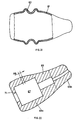
- FIG. 15 schematically shows a longitudinal sectional view of an in-ear otoplastic
- FIG. 16 a schematic cross-sectional representation of a section of this otoplastic.
- the earmold - e.g. for receiving electronic components - has a shell 45 which is stocking-like, thin-walled made of elastic material.
- the dimensional stability of the - outside smooth in the illustrated embodiment - shell skin is - where desired - ensured by on the shell integrally inside patch ribs 47, which, with respect to the shell skin, are made of the same material.
- the course of the wall thickness of shell skin 45 calculates the density and shape of the ribs 47 in advance and then constructed the earmold according to the calculated data. Again, this is the above explained Production process using additive construction processes extremely well.
- the above-described embodiment of the in-ear earmold can certainly be combined with a ventilation system, as explained with reference to FIGS. 7 to 14.
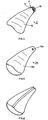
- the ribs provided for influencing the dimensional stability or bendability in certain regions of the otoplastic can also be formed with different cross-sectional profile, if necessary also progressing in their longitudinal extent progressively from one cross-section to the other.
- a pattern of ribs 51 is processed on the outer surface of the otoplastic 49, possibly with regions of different density, orientation and profile shape.
- earmold is shown schematically in a cross-sectional view in FIG.
- the interior 53 is made, for example, from a highly compressible absorption material and surrounded by a shaping skin shell 55 with the rib pattern 57.
- skin 55 and the rib pattern 57 are produced integrally together.
- the manufacturing method explained above with the aid of additive construction method is suitable. How far in the near future these additive construction processes can be realized by changing the processed materials on a workpiece remains to be seen. If this becomes possible, then the web is free, for example in the embodiment according to FIG. 20, to also sequentially build up the filler 53 simultaneously with the skin 55 and the ribs 57 in respective build-up layers.
- Ventilation channels or clearances can be formed at the same time with the aid of the outer rib patterns, as shown purely schematically and for example by the path P.
- earmolds may be provided which are likely to leave a cavity for male assemblies such as electronic components, but in which the space between such a lumen 59 is specific to the necessary volumes and shapes of additional designed units to be installed and the shell skin 55 is filled for example by a resilient or sound-absorbing material or components to be installed with such a material to the shell skin 55 are poured out.
- the shell skin 55 or 45, according to Figures 15, 16 and 17, may well be made of electrically conductive material, whereby at the same time an electrical shielding effect for internal electronic components is created. This also applies, if necessary, to the filling 53 according to FIG. 20.
- an otoplastic was illustrated using the example of an in-ear otoplastic, the shell of which is dimensionally stabilized with internal and / or external ribs, which results in an extraordinarily lightweight and selectively shapable construction.
- this design can also be used for outer ear earmolds.
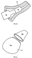
- FIG. 21 shows a further embodiment variant of an in-ear otoplastic, which is specifically bendable or compressible in one region.
- the shell 61 of an otoplastic in particular the shell of an in-ear hearing aid, has For this purpose, in one or more predetermined areas, a corrugated or corrugated hose training 63 on what they, according to the respective needs, is bendable or compressible.
- FIG. 21 illustrates this procedure on the basis of the shell of an in-ear otoplastic, this procedure can be implemented completely and, if necessary, also for an outer ear earmold. Again, the manufacturing method explained in the introduction is preferably used for this purpose.
- the inner volume of the earmold can be filled with the requisite filling material or internals integrated therein can be embedded in such filling material, resulting in a higher stability of the device and improved acoustic conditions.
- Hearing should be readjusted according to the respective hearing, yet again and again new hearing aids must be designed only due to the fact that the former no longer fit satisfactorily in the ear canal.
- an in-ear otoplasty 65 is shown schematically and in longitudinal section, to which the formation of the inner space 67 substantially corresponds to the shape of the in Fig. 23 schematically shown, male electronic module 69.
- the earmold 65 is made of rubber-elastic material and can, as shown in Fig. 23, be slipped over the electronic module 69.
- the shaping of the interior space 67 is such that the or possibly the plurality of modules to be accommodated positively positioned directly by the earmold 65 and held. Because of this approach, it is easily possible to provide one and the same electronic module 69 with different earmolds 65, so as to take into account, for example, in a growing child of the changing auditory canal training.
- the earmold is practically an easily replaceable disposable accessory for the in-ear hearing aid. Not only to take account of changing conditions in the application area, namely the ear canal, but also simply for reasons of contamination, the earmold 65 can be easily changed. This concept can even be exploited, if necessary - for example in auditory canal inflammations - to make medical applications, for example by applying drugs to the earmold outer surface or at least to use sterilized earmolds at regular intervals.
- Figs. 22 and 23 for example, as part of the module holder which is otherwise provided in conventional in-ear hearing aids Phaseplate 1 integral with the Built earmold. The same applies to other mounts and recordings for electronic components of the hearing aid. If one realizes the layer-by-layer build-up method set forth in section 1), as indicated by dash-dotted lines in FIG. 22 and in the direction indicated by the arrow AB, then it would be readily possible for the earmold to be in the abovementioned mounting direction AB as required in the respective areas of different materials to manufacture. This also applies to the earmolds described in Sections 2) and 3) as well as to those explained in the following sections 5), 6) and 7). The example of Fig. 22, it is thus quite possible to produce the region 65 a of rubber-elastic material, however, the output region 65 b of dimensionally stable material.
- FIG. 24 shows a further embodiment of an otoplastic, again by way of example with reference to an in-the-ear hearing device, which enables simple, rapid replacement of the internal fittings.
- it is proposed in this case to design the earmold shell in a multi-part and assemblable manner on an in-ear earmold with internals, as shown in FIG. 24.
- acoustical / electrical transducers or electro-acoustic output transducers on the input side or output side via acoustic conductors assembled as separate parts, namely tube-like structures, to the environment of the hearing aid. or, in particular with input-side acoustic / electrical transducers, to place them with their receiving surface directly in the area of the surfaces of the hearing aid, possibly separated from the environment only by small cavities and protective measures.
- a converter module 75 has an acoustic input or output 77.
- the shell 79 of the earmold of an in-ear or an outer-ear hearing device or a headphone has, integrated into it, an acoustic conductor 81. It lies at least in sections and as shown in FIG. 25 within the wall of the earmold shell 79.
- the respective acoustic impedance of the acoustic conductor 81 is preferably adjusted.
- This concept makes it possible to provide auditory input openings 85 along the hearing aid and where desired, to couple them to the intended acoustic / electrical transducers 91 via acoustic conductors 89 integrated in the otoplastic or its shell 87 essentially independent of where these transducers 91 are installed in the hearing aid.
- FIG. 26 centralize two transducers into a module and connect their inputs to the desired receiving apertures 85 through the aforementioned guide of the acoustic conductors 89. From consideration of FIGS.
- Ventilation channels as acoustic conductor channels, in particular if, as schematically illustrated in FIG. 25, by means of acoustic matching elements 83 the acoustic impedance conditions are designed specifically.
- each manufactured earmold is individually adapted for their respective wearer. Therefore, it would be extremely desirable to identify each manufactured earmold, as mentioned in particular every in-ear earmold, in particular every in-the-ear hearing aid. It is therefore proposed to provide in the ear or in their shell, by indentations and / or by bulges an individual identification, which in addition to the individual purchaser - eg manufacturer - product serial number, left-Rechtsapplikatioa etc. may contain. Such a marking is produced in a much preferred manner in the manufacture of the otoplastic with the removal method described under 1). This ensures that any confusion of the earmoulds is excluded from the production. This is especially important in the subsequent, possibly automated assembly with other modules, such as the assembly of in-ear hearing aids.
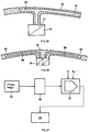
- the dynamical application area represented by the block 93 takes form at several positions corresponding to the actual dynamics or, similar to a film, the dynamics of the application area per se registered.
- the resulting data records are stored in a memory unit 95. Even with conventional procedure by impression taking, this can certainly be realized by the application area in two or more positions of the Practical dynamics corresponding impressions are taken.
- the dynamics of the application area can be detected by X-ray images.
- the arithmetic unit 97 controls the manufacturing process 99 for the earmold. If, for example, and as is customary to date, in-ear earmolds are manufactured with a relatively hard shell, the arithmetic unit 97 calculates the dynamic data stored on the memory unit 95 and, as shown schematically at K, further manufacturing parameters, the best fit for the earmold, so that optimal comfort in everyday life is achieved, while preserving their functionality.
- the arithmetic unit 97 determines which earmold areas are to be designed in terms of their flexibility, bendability, compressibility, etc. As mentioned, the arithmetic unit 97 controls the production process 99 on the output side , preferably the manufacturing process as set out in section 1) as a preferred process.
Landscapes
- Health & Medical Sciences (AREA)
- Life Sciences & Earth Sciences (AREA)
- Biomedical Technology (AREA)
- Acoustics & Sound (AREA)
- Biophysics (AREA)
- Otolaryngology (AREA)
- Psychology (AREA)
- Engineering & Computer Science (AREA)
- Physics & Mathematics (AREA)
- Heart & Thoracic Surgery (AREA)
- Vascular Medicine (AREA)
- Animal Behavior & Ethology (AREA)
- General Health & Medical Sciences (AREA)
- Public Health (AREA)
- Veterinary Medicine (AREA)
- Headphones And Earphones (AREA)
- Orthopedics, Nursing, And Contraception (AREA)
- Helmets And Other Head Coverings (AREA)
Abstract
Claims (9)
- Otoplastique avec une coque (45, 55) en un matériau élastique, caractérisée en ce que la coque (45, 55) a au moins dans un tronçon un motif bidimensionnel avec des nervures (47, 51, 57) intégrales étendues longitudinalement à sa surface extérieure et/ou intérieure, sachant que les nervures augmentent l'épaisseur de paroi de la coque dans leurs zones et que la stabilité de forme de la coque dans le tronçon est essentiellement assurée par le motif de nervures.
- Otoplastique selon la revendication 1, caractérisée en ce que les nervures (47) forment un motif de grille.
- Otoplastique selon l'une des revendications 1 ou 2, caractérisée en ce que les nervures (47) ont des profils différents.
- Otoplastique selon l'une des revendications 1 à 3, caractérisée en ce que les nervures (47) présentent un profil qui varie dans leur extension longitudinale.
- Otoplastique selon l'une des revendications 1 à 4, avec une zone à tourner vers le tympan ainsi qu'une à tourner vers l'environnement de l'oreille, caractérisée en ce que les nervures (51) définissent à la surface extérieure de l'otoplastique au moins une rigole (P) s'étendant entre les zones comme rigole de ventilation.
- Otoplastique selon l'une des revendications 1 à 5, caractérisée en ce que la coque est essentiellement remplie d'un matériau de remplissage (53) adapté à la fonction de l'otoplastique.
- Otoplastique selon la revendication 6, caractérisée en ce que dans le matériau de remplissage est prévu au moins un logement (59) pour un module à intégrer dans l'otoplastique.
- Otoplastique selon la revendication 7 avec module électronique intégré.
- Otoplastique selon la revendication 8, caractérisée en ce qu'elle est un appareil de correction auditive, de préférence un appareil « dans l'oreille ».
Applications Claiming Priority (1)
| Application Number | Priority Date | Filing Date | Title |
|---|---|---|---|
| PCT/CH2000/000522 WO2002024129A1 (fr) | 2000-09-25 | 2000-09-25 | Otoplastique |
Publications (2)
| Publication Number | Publication Date |
|---|---|
| EP1320341A1 EP1320341A1 (fr) | 2003-06-25 |
| EP1320341B1 true EP1320341B1 (fr) | 2006-11-02 |
Family
ID=4358135
Family Applications (1)
| Application Number | Title | Priority Date | Filing Date |
|---|---|---|---|
| EP00960276A Expired - Lifetime EP1320341B1 (fr) | 2000-09-25 | 2000-09-25 | Otoplastique |
Country Status (7)
| Country | Link |
|---|---|
| EP (1) | EP1320341B1 (fr) |
| JP (1) | JP2004508786A (fr) |
| AU (2) | AU2000272657B2 (fr) |
| CA (1) | CA2422924C (fr) |
| DE (1) | DE50013705D1 (fr) |
| DK (1) | DK1320341T3 (fr) |
| WO (1) | WO2002024129A1 (fr) |
Families Citing this family (4)
| Publication number | Priority date | Publication date | Assignee | Title |
|---|---|---|---|---|
| EP1629809A1 (fr) | 2004-08-25 | 2006-03-01 | Phonak Ag | Bouchon de protection auriculaire personnalisé et son procédé de fabrication |
| US7478702B2 (en) | 2004-08-25 | 2009-01-20 | Phonak Ag | Customized hearing protection earplug and method for manufacturing the same |
| US7886745B2 (en) * | 2008-06-30 | 2011-02-15 | Kimberly-Clark Worldwide, Inc. | Self-fitting device for location in an ear canal |
| KR101695393B1 (ko) * | 2015-07-21 | 2017-01-11 | 박제원 | 보청기 |
Family Cites Families (4)
| Publication number | Priority date | Publication date | Assignee | Title |
|---|---|---|---|---|
| US1830198A (en) * | 1930-08-21 | 1931-11-03 | French Electric Company Inc | Ear receiver nipple |
| US3896801A (en) * | 1973-05-29 | 1975-07-29 | Kenneth M Grout | Ear plug |
| US5572594A (en) * | 1994-09-27 | 1996-11-05 | Devoe; Lambert | Ear canal device holder |
| DE19843389C2 (de) * | 1998-09-22 | 2002-07-11 | Fariborz-Hassan Dirinpur | Perforierte Otoplastik für Hörgeräte |
-
2000
- 2000-09-25 CA CA002422924A patent/CA2422924C/fr not_active Expired - Lifetime
- 2000-09-25 DE DE50013705T patent/DE50013705D1/de not_active Expired - Lifetime
- 2000-09-25 WO PCT/CH2000/000522 patent/WO2002024129A1/fr not_active Ceased
- 2000-09-25 DK DK00960276T patent/DK1320341T3/da active
- 2000-09-25 AU AU2000272657A patent/AU2000272657B2/en not_active Expired
- 2000-09-25 EP EP00960276A patent/EP1320341B1/fr not_active Expired - Lifetime
- 2000-09-25 AU AU7265700A patent/AU7265700A/xx active Pending
- 2000-09-25 JP JP2002528169A patent/JP2004508786A/ja active Pending
Also Published As
| Publication number | Publication date |
|---|---|
| AU7265700A (en) | 2002-04-02 |
| CA2422924C (fr) | 2009-08-04 |
| JP2004508786A (ja) | 2004-03-18 |
| AU2000272657B2 (en) | 2006-05-18 |
| DE50013705D1 (en) | 2006-12-14 |
| CA2422924A1 (fr) | 2003-03-20 |
| WO2002024129A1 (fr) | 2002-03-28 |
| EP1320341A1 (fr) | 2003-06-25 |
| DK1320341T3 (da) | 2007-03-05 |
Similar Documents
| Publication | Publication Date | Title |
|---|---|---|
| EP1320339B1 (fr) | Otoplastique et procede de fabrication d'un otoplastique | |
| EP1295509B1 (fr) | Procede de fabrication d'otoplastiques et otoplastique y relatif | |
| US7387187B2 (en) | Custom-molded ear-plug, and process for producing a custom-molded ear-plug device | |
| US6595317B1 (en) | Custom-moulded ear-plug device | |
| AU2002300247B2 (en) | Method for manufacturing an ear device and ear device | |
| US6540045B1 (en) | Method for manufacturing an ear device and ear device | |
| US6401859B1 (en) | Custom-molded ear-plug, and process for producing a custom-molded ear-plug device | |
| EP3579580B1 (fr) | Procédé de fabrication d'un composant d'un appareil auditif | |
| EP1463375B1 (fr) | Prothèse auditive pour l'oreille externe avec un moulage auriculaire | |
| EP1320341B1 (fr) | Otoplastique | |
| EP1323331B1 (fr) | Procede de production d'otoplastiques | |
| EP1321011B1 (fr) | Otoplastique avec module integre, otoplastique place dans l'oreille et procede d'adaptation des otoplastiques | |
| EP1320340A1 (fr) | Prothese auditive intra-auriculaire | |
| DE202004011467U1 (de) | Gehörgangsplastik für Hinter-dem-Ohr-Hörgeräte | |
| AU2008201247B2 (en) | Apparatus and Method for Applying a Substance to a Human Body | |
| DE102024102515A1 (de) | Hörgerät mit einer Schale, die einen komprimierbaren Bereich enthält, und Verfahren zur Herstellung desselben | |
| DE102010011509A1 (de) | Selektiver- individueller Gehör- und Lärmschutz |
Legal Events
| Date | Code | Title | Description |
|---|---|---|---|
| PUAI | Public reference made under article 153(3) epc to a published international application that has entered the european phase |
Free format text: ORIGINAL CODE: 0009012 |
|
| 17P | Request for examination filed |
Effective date: 20030207 |
|
| AK | Designated contracting states |
Designated state(s): AT BE CH CY DE DK ES FI FR GB GR IE IT LI LU MC NL PT SE |
|
| AX | Request for extension of the european patent |
Extension state: AL LT LV MK RO SI |
|
| RBV | Designated contracting states (corrected) |
Designated state(s): AT BE CH CY DE DK FR GB IT LI |
|
| 17Q | First examination report despatched |
Effective date: 20041022 |
|
| GRAP | Despatch of communication of intention to grant a patent |
Free format text: ORIGINAL CODE: EPIDOSNIGR1 |
|
| RBV | Designated contracting states (corrected) |
Designated state(s): CH DE DK FR GB IT LI |
|
| RIN1 | Information on inventor provided before grant (corrected) |
Inventor name: HESSEL, HANS Inventor name: WEIDMANN, MARKUS Inventor name: WIDMER, CHRISTOPH |
|
| GRAS | Grant fee paid |
Free format text: ORIGINAL CODE: EPIDOSNIGR3 |
|
| GRAA | (expected) grant |
Free format text: ORIGINAL CODE: 0009210 |
|
| AK | Designated contracting states |
Kind code of ref document: B1 Designated state(s): CH DE DK FR GB IT LI |
|
| PG25 | Lapsed in a contracting state [announced via postgrant information from national office to epo] |
Ref country code: IT Free format text: LAPSE BECAUSE OF FAILURE TO SUBMIT A TRANSLATION OF THE DESCRIPTION OR TO PAY THE FEE WITHIN THE PRESCRIBED TIME-LIMIT;WARNING: LAPSES OF ITALIAN PATENTS WITH EFFECTIVE DATE BEFORE 2007 MAY HAVE OCCURRED AT ANY TIME BEFORE 2007. THE CORRECT EFFECTIVE DATE MAY BE DIFFERENT FROM THE ONE RECORDED. Effective date: 20061102 |
|
| REG | Reference to a national code |
Ref country code: GB Ref legal event code: FG4D Free format text: NOT ENGLISH |
|
| REG | Reference to a national code |
Ref country code: CH Ref legal event code: EP |
|
| GBT | Gb: translation of ep patent filed (gb section 77(6)(a)/1977) |
Effective date: 20061122 |
|
| REF | Corresponds to: |
Ref document number: 50013705 Country of ref document: DE Date of ref document: 20061214 Kind code of ref document: P |
|
| REG | Reference to a national code |
Ref country code: CH Ref legal event code: NV Representative=s name: TROESCH SCHEIDEGGER WERNER AG |
|
| REG | Reference to a national code |
Ref country code: DK Ref legal event code: T3 |
|
| ET | Fr: translation filed | ||
| PLBE | No opposition filed within time limit |
Free format text: ORIGINAL CODE: 0009261 |
|
| STAA | Information on the status of an ep patent application or granted ep patent |
Free format text: STATUS: NO OPPOSITION FILED WITHIN TIME LIMIT |
|
| 26N | No opposition filed |
Effective date: 20070803 |
|
| REG | Reference to a national code |
Ref country code: FR Ref legal event code: PLFP Year of fee payment: 17 |
|
| REG | Reference to a national code |
Ref country code: FR Ref legal event code: PLFP Year of fee payment: 18 |
|
| REG | Reference to a national code |
Ref country code: FR Ref legal event code: PLFP Year of fee payment: 19 |
|
| PGFP | Annual fee paid to national office [announced via postgrant information from national office to epo] |
Ref country code: GB Payment date: 20180927 Year of fee payment: 19 |
|
| PGFP | Annual fee paid to national office [announced via postgrant information from national office to epo] |
Ref country code: CH Payment date: 20181002 Year of fee payment: 19 |
|
| REG | Reference to a national code |
Ref country code: DE Ref legal event code: R084 Ref document number: 50013705 Country of ref document: DE |
|
| PGFP | Annual fee paid to national office [announced via postgrant information from national office to epo] |
Ref country code: FR Payment date: 20190925 Year of fee payment: 20 Ref country code: DK Payment date: 20190927 Year of fee payment: 20 |
|
| PGFP | Annual fee paid to national office [announced via postgrant information from national office to epo] |
Ref country code: DE Payment date: 20190927 Year of fee payment: 20 |
|
| REG | Reference to a national code |
Ref country code: CH Ref legal event code: PL |
|
| PG25 | Lapsed in a contracting state [announced via postgrant information from national office to epo] |
Ref country code: LI Free format text: LAPSE BECAUSE OF NON-PAYMENT OF DUE FEES Effective date: 20190930 Ref country code: CH Free format text: LAPSE BECAUSE OF NON-PAYMENT OF DUE FEES Effective date: 20190930 |
|
| GBPC | Gb: european patent ceased through non-payment of renewal fee |
Effective date: 20190925 |
|
| REG | Reference to a national code |
Ref country code: DE Ref legal event code: R071 Ref document number: 50013705 Country of ref document: DE |
|
| REG | Reference to a national code |
Ref country code: DK Ref legal event code: EUP Expiry date: 20200925 |
|
| PG25 | Lapsed in a contracting state [announced via postgrant information from national office to epo] |
Ref country code: GB Free format text: LAPSE BECAUSE OF NON-PAYMENT OF DUE FEES Effective date: 20190925 |