EP1320636B9 - Procede et dispositif pour l'extraction notamment de couches organiques dans le cadre de la deposition en phase vapeur organique - Google Patents
Procede et dispositif pour l'extraction notamment de couches organiques dans le cadre de la deposition en phase vapeur organique Download PDFInfo
- Publication number
- EP1320636B9 EP1320636B9 EP01974282A EP01974282A EP1320636B9 EP 1320636 B9 EP1320636 B9 EP 1320636B9 EP 01974282 A EP01974282 A EP 01974282A EP 01974282 A EP01974282 A EP 01974282A EP 1320636 B9 EP1320636 B9 EP 1320636B9
- Authority
- EP
- European Patent Office
- Prior art keywords
- starting material
- vessel
- gas
- carrier gas
- container
- Prior art date
- Legal status (The legal status is an assumption and is not a legal conclusion. Google has not performed a legal analysis and makes no representation as to the accuracy of the status listed.)
- Expired - Lifetime
Links
- 238000000034 method Methods 0.000 title claims description 18
- 238000000151 deposition Methods 0.000 title claims description 3
- 239000012044 organic layer Substances 0.000 title description 2
- 238000001947 vapour-phase growth Methods 0.000 title description 2
- 239000012159 carrier gas Substances 0.000 claims description 40
- 239000007858 starting material Substances 0.000 claims description 39
- 239000007789 gas Substances 0.000 claims description 23
- 238000005192 partition Methods 0.000 claims description 20
- 238000010438 heat treatment Methods 0.000 claims description 12
- 239000000758 substrate Substances 0.000 claims description 10
- 239000011368 organic material Substances 0.000 claims description 6
- 238000001704 evaporation Methods 0.000 claims description 4
- 229910052751 metal Inorganic materials 0.000 claims description 4
- 239000002184 metal Substances 0.000 claims description 4
- 230000008020 evaporation Effects 0.000 claims description 3
- 239000008187 granular material Substances 0.000 claims description 2
- 239000000843 powder Substances 0.000 claims description 2
- 229920006395 saturated elastomer Polymers 0.000 claims description 2
- 238000011144 upstream manufacturing Methods 0.000 claims description 2
- 238000011010 flushing procedure Methods 0.000 claims 1
- 239000002994 raw material Substances 0.000 description 7
- 239000007788 liquid Substances 0.000 description 3
- 239000000463 material Substances 0.000 description 3
- IJGRMHOSHXDMSA-UHFFFAOYSA-N Atomic nitrogen Chemical compound N#N IJGRMHOSHXDMSA-UHFFFAOYSA-N 0.000 description 2
- 229910052782 aluminium Inorganic materials 0.000 description 2
- XAGFODPZIPBFFR-UHFFFAOYSA-N aluminium Chemical compound [Al] XAGFODPZIPBFFR-UHFFFAOYSA-N 0.000 description 2
- 238000001816 cooling Methods 0.000 description 2
- 238000000859 sublimation Methods 0.000 description 2
- 230000008022 sublimation Effects 0.000 description 2
- 206010067482 No adverse event Diseases 0.000 description 1
- 238000009833 condensation Methods 0.000 description 1
- 230000005494 condensation Effects 0.000 description 1
- 238000010276 construction Methods 0.000 description 1
- 230000008021 deposition Effects 0.000 description 1
- 238000009795 derivation Methods 0.000 description 1
- 239000010410 layer Substances 0.000 description 1
- 238000004519 manufacturing process Methods 0.000 description 1
- 239000000155 melt Substances 0.000 description 1
- 229910052757 nitrogen Inorganic materials 0.000 description 1
- 239000002245 particle Substances 0.000 description 1
- 239000012071 phase Substances 0.000 description 1
- 239000011148 porous material Substances 0.000 description 1
- 150000003839 salts Chemical class 0.000 description 1
- 239000007787 solid Substances 0.000 description 1
Images


Classifications
-
- C—CHEMISTRY; METALLURGY
- C23—COATING METALLIC MATERIAL; COATING MATERIAL WITH METALLIC MATERIAL; CHEMICAL SURFACE TREATMENT; DIFFUSION TREATMENT OF METALLIC MATERIAL; COATING BY VACUUM EVAPORATION, BY SPUTTERING, BY ION IMPLANTATION OR BY CHEMICAL VAPOUR DEPOSITION, IN GENERAL; INHIBITING CORROSION OF METALLIC MATERIAL OR INCRUSTATION IN GENERAL
- C23C—COATING METALLIC MATERIAL; COATING MATERIAL WITH METALLIC MATERIAL; SURFACE TREATMENT OF METALLIC MATERIAL BY DIFFUSION INTO THE SURFACE, BY CHEMICAL CONVERSION OR SUBSTITUTION; COATING BY VACUUM EVAPORATION, BY SPUTTERING, BY ION IMPLANTATION OR BY CHEMICAL VAPOUR DEPOSITION, IN GENERAL
- C23C14/00—Coating by vacuum evaporation, by sputtering or by ion implantation of the coating forming material
- C23C14/22—Coating by vacuum evaporation, by sputtering or by ion implantation of the coating forming material characterised by the process of coating
- C23C14/228—Gas flow assisted PVD deposition
-
- C—CHEMISTRY; METALLURGY
- C23—COATING METALLIC MATERIAL; COATING MATERIAL WITH METALLIC MATERIAL; CHEMICAL SURFACE TREATMENT; DIFFUSION TREATMENT OF METALLIC MATERIAL; COATING BY VACUUM EVAPORATION, BY SPUTTERING, BY ION IMPLANTATION OR BY CHEMICAL VAPOUR DEPOSITION, IN GENERAL; INHIBITING CORROSION OF METALLIC MATERIAL OR INCRUSTATION IN GENERAL
- C23C—COATING METALLIC MATERIAL; COATING MATERIAL WITH METALLIC MATERIAL; SURFACE TREATMENT OF METALLIC MATERIAL BY DIFFUSION INTO THE SURFACE, BY CHEMICAL CONVERSION OR SUBSTITUTION; COATING BY VACUUM EVAPORATION, BY SPUTTERING, BY ION IMPLANTATION OR BY CHEMICAL VAPOUR DEPOSITION, IN GENERAL
- C23C14/00—Coating by vacuum evaporation, by sputtering or by ion implantation of the coating forming material
- C23C14/06—Coating by vacuum evaporation, by sputtering or by ion implantation of the coating forming material characterised by the coating material
- C23C14/12—Organic material
-
- C—CHEMISTRY; METALLURGY
- C23—COATING METALLIC MATERIAL; COATING MATERIAL WITH METALLIC MATERIAL; CHEMICAL SURFACE TREATMENT; DIFFUSION TREATMENT OF METALLIC MATERIAL; COATING BY VACUUM EVAPORATION, BY SPUTTERING, BY ION IMPLANTATION OR BY CHEMICAL VAPOUR DEPOSITION, IN GENERAL; INHIBITING CORROSION OF METALLIC MATERIAL OR INCRUSTATION IN GENERAL
- C23C—COATING METALLIC MATERIAL; COATING MATERIAL WITH METALLIC MATERIAL; SURFACE TREATMENT OF METALLIC MATERIAL BY DIFFUSION INTO THE SURFACE, BY CHEMICAL CONVERSION OR SUBSTITUTION; COATING BY VACUUM EVAPORATION, BY SPUTTERING, BY ION IMPLANTATION OR BY CHEMICAL VAPOUR DEPOSITION, IN GENERAL
- C23C14/00—Coating by vacuum evaporation, by sputtering or by ion implantation of the coating forming material
- C23C14/06—Coating by vacuum evaporation, by sputtering or by ion implantation of the coating forming material characterised by the coating material
- C23C14/14—Metallic material, boron or silicon
- C23C14/18—Metallic material, boron or silicon on other inorganic substrates
- C23C14/185—Metallic material, boron or silicon on other inorganic substrates by cathodic sputtering
-
- C—CHEMISTRY; METALLURGY
- C23—COATING METALLIC MATERIAL; COATING MATERIAL WITH METALLIC MATERIAL; CHEMICAL SURFACE TREATMENT; DIFFUSION TREATMENT OF METALLIC MATERIAL; COATING BY VACUUM EVAPORATION, BY SPUTTERING, BY ION IMPLANTATION OR BY CHEMICAL VAPOUR DEPOSITION, IN GENERAL; INHIBITING CORROSION OF METALLIC MATERIAL OR INCRUSTATION IN GENERAL
- C23C—COATING METALLIC MATERIAL; COATING MATERIAL WITH METALLIC MATERIAL; SURFACE TREATMENT OF METALLIC MATERIAL BY DIFFUSION INTO THE SURFACE, BY CHEMICAL CONVERSION OR SUBSTITUTION; COATING BY VACUUM EVAPORATION, BY SPUTTERING, BY ION IMPLANTATION OR BY CHEMICAL VAPOUR DEPOSITION, IN GENERAL
- C23C16/00—Chemical coating by decomposition of gaseous compounds, without leaving reaction products of surface material in the coating, i.e. chemical vapour deposition [CVD] processes
- C23C16/44—Chemical coating by decomposition of gaseous compounds, without leaving reaction products of surface material in the coating, i.e. chemical vapour deposition [CVD] processes characterised by the method of coating
- C23C16/4401—Means for minimising impurities, e.g. dust, moisture or residual gas, in the reaction chamber
- C23C16/4402—Reduction of impurities in the source gas
-
- C—CHEMISTRY; METALLURGY
- C23—COATING METALLIC MATERIAL; COATING MATERIAL WITH METALLIC MATERIAL; CHEMICAL SURFACE TREATMENT; DIFFUSION TREATMENT OF METALLIC MATERIAL; COATING BY VACUUM EVAPORATION, BY SPUTTERING, BY ION IMPLANTATION OR BY CHEMICAL VAPOUR DEPOSITION, IN GENERAL; INHIBITING CORROSION OF METALLIC MATERIAL OR INCRUSTATION IN GENERAL
- C23C—COATING METALLIC MATERIAL; COATING MATERIAL WITH METALLIC MATERIAL; SURFACE TREATMENT OF METALLIC MATERIAL BY DIFFUSION INTO THE SURFACE, BY CHEMICAL CONVERSION OR SUBSTITUTION; COATING BY VACUUM EVAPORATION, BY SPUTTERING, BY ION IMPLANTATION OR BY CHEMICAL VAPOUR DEPOSITION, IN GENERAL
- C23C16/00—Chemical coating by decomposition of gaseous compounds, without leaving reaction products of surface material in the coating, i.e. chemical vapour deposition [CVD] processes
- C23C16/44—Chemical coating by decomposition of gaseous compounds, without leaving reaction products of surface material in the coating, i.e. chemical vapour deposition [CVD] processes characterised by the method of coating
- C23C16/448—Chemical coating by decomposition of gaseous compounds, without leaving reaction products of surface material in the coating, i.e. chemical vapour deposition [CVD] processes characterised by the method of coating characterised by the method used for generating reactive gas streams, e.g. by evaporation or sublimation of precursor materials
- C23C16/4481—Chemical coating by decomposition of gaseous compounds, without leaving reaction products of surface material in the coating, i.e. chemical vapour deposition [CVD] processes characterised by the method of coating characterised by the method used for generating reactive gas streams, e.g. by evaporation or sublimation of precursor materials by evaporation using carrier gas in contact with the source material
-
- Y—GENERAL TAGGING OF NEW TECHNOLOGICAL DEVELOPMENTS; GENERAL TAGGING OF CROSS-SECTIONAL TECHNOLOGIES SPANNING OVER SEVERAL SECTIONS OF THE IPC; TECHNICAL SUBJECTS COVERED BY FORMER USPC CROSS-REFERENCE ART COLLECTIONS [XRACs] AND DIGESTS
- Y10—TECHNICAL SUBJECTS COVERED BY FORMER USPC
- Y10T—TECHNICAL SUBJECTS COVERED BY FORMER US CLASSIFICATION
- Y10T117/00—Single-crystal, oriented-crystal, and epitaxy growth processes; non-coating apparatus therefor
- Y10T117/10—Apparatus
- Y10T117/1004—Apparatus with means for measuring, testing, or sensing
-
- Y—GENERAL TAGGING OF NEW TECHNOLOGICAL DEVELOPMENTS; GENERAL TAGGING OF CROSS-SECTIONAL TECHNOLOGIES SPANNING OVER SEVERAL SECTIONS OF THE IPC; TECHNICAL SUBJECTS COVERED BY FORMER USPC CROSS-REFERENCE ART COLLECTIONS [XRACs] AND DIGESTS
- Y10—TECHNICAL SUBJECTS COVERED BY FORMER USPC
- Y10T—TECHNICAL SUBJECTS COVERED BY FORMER US CLASSIFICATION
- Y10T117/00—Single-crystal, oriented-crystal, and epitaxy growth processes; non-coating apparatus therefor
- Y10T117/10—Apparatus
- Y10T117/1004—Apparatus with means for measuring, testing, or sensing
- Y10T117/1008—Apparatus with means for measuring, testing, or sensing with responsive control means
Definitions
- the invention relates to a method for deposition special organic layers, in which in one heated reactor in one formed by a container Source of stored, non-gaseous starting material by means of a carrier gas in the gaseous state is transported from the source to a substrate, where he deposited on the substrate.
- OLEDs organic light-emitting diodes
- OVPD Organic Vapor Phase Deposition
- Organic molecules are used as starting materials, which are present in particular as salts and in granular form, but can also be in the liquid state. These molecules have a very low vapor pressure.
- the container is an open-topped tank in which the starting material is contained. This trough is inserted into a source zone of the heated reactor.
- the starting material evaporating from the granulate bed or from a melt is transported through the reactor by means of a carrier gas, for example nitrogen.
- the substrate may be at a substrate temperature that is less than the source temperature.
- the source material can be deposited there. Process pressures of 0.2 mbar are used in the prior art.
- the invention has for its object to provide measures to the Predict growth rates more precisely and more efficiently than Larger substrate areas known to date from the prior art coat.
- the problem is solved by that specified in claim 1 Method or by the device specified in claim 5.
- the invention is based on the finding that, according to the source non-reproducible adjustable heat supply and cooling through the carrier gas has an unpredictable gaseous production rate Has raw material. What the fluctuating ones considered to be disadvantageous Entails growth rates.
- the process aims to ensure that Carrier gas is preheated and heated from bottom to top Container side walls isothermal to the carrier gas held starting material flushed. Since the carrier gas flowing into the container is the same Has temperature like that through heat transfer from the container walls heated starting material, cooling no longer takes place.
- the Heat of condensation which is particularly powdery or granular Starting material that is removed during evaporation is removed via the side walls fed again. To support the heat supply can also Project heating elements into the raw material.
- the process parameters are preferably set so that the carrier gas is already a few millimeters behind Contacting the source is saturated.
- the Saturation takes place in the lower third or fifth of the receiving chamber.
- the container can be refilled from above become.
- the carrier gas is preferably preheated by the same heater that also heats the container.
- Metal comes in particular as the container wall, preferably aluminum.
- the device according to the invention is characterized in that the Container has a bottom-side gas inlet and a lid-side gas outlet and between the gas inlet and gas outlet one with the starting material has refillable receiving chamber, and the container walls and the in a heater is assigned to the carrier gas supply line opening into the gas inlet for isothermal heating of the carrier gas and the starting material.
- the receiving chamber can also be designed as an insert. This use can then be replaced. The insert is inserted into the container. He contains the organic material. If the material is used up or partially used, so the insert can be removed and exchanged for a full one become.
- the container is encircled and has in addition to the inlet or Outlet opening preferably only one refill opening.
- the container is a gas permeable above the gas inlet Partition wall, which can consist of porous material.
- the partition can be designed as a frit. The is on this partition in particular powder or granular starting material as a bed.
- the Carrier gas is brought up to the source temperature by an upstream heater brought. This carrier gas then passes through the porous partition wall evenly through and flushed the bed lying on the partition. It it is also possible to use liquid raw materials. Then the carrier gas flushes the liquid, similar to the case with a wash bottle.
- the partition can be flat, but it can also be dome-shaped be conical.
- the device protrude into the starting material heating rods one that can be heated separately, or thermally conductive are connected to the container wall to the To supply heat as a starting material.
- the receiving chamber can be refillable from above.
- a pantry can be provided above the reception chamber.
- Pantry can stock up on the source material are located. This can be done via a lockable channel be fed to the receiving chamber to refill them.
- the pantry does not need to be heated. It can even be arranged outside the reactor and only with a refill connection to the reactor or be connected to the container.
- the carrier gas 4 is heated from the outside Reactor 1 fed.
- the source zone I a Container 2 placed in the reactor, which is a bed of Contains starting material.
- the raw material sublimates at Source temperature.
- the gaseous starting material 5 is then with the Carrier gas 4 transported to the substrate II, where it condenses from the gas phase, to deposit a layer there.
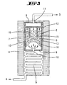
- the container 2 is closed according to the invention. He has a bottom 8, in particular cylindrical Side walls 13 and a lid 9. The bottom has a gas inlet 10. The lid has a gas outlet 11.
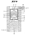
- In the lower part of the metal, in particular Aluminum existing container 2 is one Inflow space in which the carrier gas 4, which by the carrier gas supply line 14 flows, can flow. To above this space is formed by a porous partition 16 limited. The gas flow passes through this partition through and into the poured on the partition 16 Starting material 3. Starting material 3 is from below flushed upwards by the carrier gas 4, which Carrier gas is already immediately above the partition 16 saturates with the gaseous starting material and together with the gaseous starting material 5 exits the gas outlet 11 into the reactor.
- the whole Device as shown in FIGS. 2 to 5 can be integrated into the reactor.
- the reactor is structurally adjusted.
- the feed line 14 is heated by a heater 6. This heats the carrier gas 4 to the same temperature, that of the starting material 3 in the above the partition 16 arranged receiving chamber 12 has.
- the container 2 has a container heater 7.
- the container heater 7 surrounds the outer Container wall 13 to heat it up. Through heat conduction the container wall 13 is supplied Heat supplied to the starting material 3.
- the Heater 6 of the carrier gas supply line 14 has the same heater, as the container heating 7.
- the carrier gas supply line 14 be designed in a helical shape. at the embodiment shown in Fig. 3 is the Partition 16 designed dome-shaped. Also protrude there heating rods 15 in the bed of the starting material 3 in. The heating rods 15 are thermally connected with the container wall 13.
- the partition 16 has a conical shape.
- the supply line for the carrier gas or the derivation of the same can through openings in the container and the Supply line 14 surrounding heater 6, 7 take place.
- the receiving chamber 12 can be refilled from above.
- a filling channel 19 opens into the container lid.
- This Filling channel 19 can be closed with a closure 18 become.
- the pantry can are outside the reactor and be larger than shown.
- FIG. 6 shows that the partial pressure P of the starting material in the carrier gas even at a minor Route D above the partition 16 den Has reached saturation pressure, causing source depletion even if the level does not take place the receiving chamber 12 sinks.
- the measures according to the invention ensure that as the source revenue affected Parameters such as source temperature and free surface of the raw material no adverse effects have more on the reproducibility of the growth rate.
- a filter 20 in. is in front of the gas outlet in the reactor Shape of a frit is provided to prevent Solid particles or drops from the container into the Reactor are transported.
- the carrier gas with is brought into the container at an elevated temperature.
- the Heat required for sublimation of the raw material is then at least partially the carrier gas are removed, the carrier gas then on the Container wall temperature cools down, so that isothermal again Conditions prevail.
- the carrier gas can be heated in that the Partition 16 is heated.
- the partition can be used for this 16 be made of metal.
- the container is going from bottom to bottom flows through above.
- the invention also includes such Embodiments where the gas flow is different runs around, namely from top to bottom.
- such Containers then have a gas inlet on the lid side and a gas outlet on the bottom.
- the invention also relates to such embodiments, where the organic material is in use is housed, which are inserted into the container can. Then it doesn't have to be the organic material be poured directly into the container. It can be pre-assembled in the inserts. This Inserts can then be inserted into the container. This enables rapid replacement in particular. different organic materials.
Landscapes
- Chemical & Material Sciences (AREA)
- Chemical Kinetics & Catalysis (AREA)
- Engineering & Computer Science (AREA)
- Materials Engineering (AREA)
- Mechanical Engineering (AREA)
- Metallurgy (AREA)
- Organic Chemistry (AREA)
- General Chemical & Material Sciences (AREA)
- Inorganic Chemistry (AREA)
- Chemical Vapour Deposition (AREA)
- Electroluminescent Light Sources (AREA)
- Physical Vapour Deposition (AREA)
Claims (12)
- Procédé de déposition de couches à base d'un matériau organique, dans lequel une substance de départ (3) non gazeuse stockée dans une source (I) constituée d'un réservoir (2) et qui comporte une faible tension de vapeur, est transportée à l'état gazeux vers un substrat (II) au moyen d'un gaz vecteur (4), sachant que le substrat se trouve dans un réacteur (1) chauffé et que la substance de départ gazeuse, du fait que la température du substrat, qui est plus basse que la température de la source, se condense en formant une couche sur le substrat, les parois du réservoir (2) chauffés par un dispositif de chauffage (6) et le gaz vecteur parcourant de bas en haut la substance de départ stockée dans le réservoir (2), et la température du gaz vecteur affluent correspondant à la température de la substance de départ.
- Procédé selon la revendication 1, caractérisé en ce que la chaleur latente d'évaporation est fournie à la substance de départ (3) via les parois du réservoir (13) et/ou via des baguettes chauffantes (15) faisant saillie dans la substance de départ (3).
- Procédé selon l'une des revendications précédentes, caractérisé en ce que le gaz vecteur est saturé en substance de départ gazeuse dès le tiers inférieur, de préférence dès le cinquième inférieur de la chambre d'admission.
- Procédé selon l'une des revendications précédentes, caractérisé en ce que le réservoir (2) est rempli par le haut.
- Dispositif d'exécution d'un procédé selon l'une des revendications précédentes, avec une source (I) constituée d'un réservoir (2) disposée à l'avant d'un réacteur chauffé, réservoir admettant une substance de départ (3) non gazeuse, sachant que le réservoir (2) possède en bas une entrée (10), en haut une sortie (11) pour le gaz et entre l'entrée (10) pour le gaz et la sortie (11) pour le gaz une chambre d'admission (12) que l'on peut remplir de la substance de départ (3), et qu'un dispositif de chauffage commun (6, 7) est adjoint aux parois du réservoir (13) ainsi qu'aux conduites d'amenée (14) de gaz vecteur débouchant dans l'entrée (10) pour le gaz, pour réchauffer de façon isotherme le gaz vecteur (4) et la substance de départ (3).
- Dispositif selon la revendication 5, caractérisé en ce que le réservoir (2) possède une cloison (16) perméable aux gaz écartée de l'entrée pour le gaz, et sur laquelle repose la substance de départ, en particulier granulée ou sous forme poudreuse.
- Dispositif selon la revendication 6, caractérisé en ce que la cloison (16) est plane, en forme de calotte, ou conique.
- Dispositif selon l'une des revendications précédentes, caractérisé par des baguettes chauffantes (15) faisant saillie dans l'admission (12).
- Dispositif selon l'une des revendications précédentes, caractérisé par une réserve (17) disposée au-dessus de la chambre d'admission (12), laquelle réserve est reliée à la chambre d'admission (12) par un canal (19) que l'on peut fermer.
- Dispositif selon l'une des revendications précédentes, caractérisé en ce que la cloison (16) peut être chauffée et se compose en particulier de métal.
- Dispositif selon l'une des revendications précédentes, caractérisé en ce que la sortie (11) pour le gaz comprend un filtre, en particulier sous la forme d'un fritté.
- Dispositif selon l'une quelconque des revendications qui précèdent, caractérisé par une garniture que l'on peut remplir du matériau organique, laquelle garniture peut être introduite dans le réservoir (2) et possède une paroi de garniture perméable aux gaz, laquelle paroi peut être traversée par le gaz qui balaie le réservoir.
Applications Claiming Priority (3)
| Application Number | Priority Date | Filing Date | Title |
|---|---|---|---|
| DE10048759A DE10048759A1 (de) | 2000-09-29 | 2000-09-29 | Verfahren und Vorrichtung zum Abscheiden insbesondere organischer Schichten im Wege der OVPD |
| DE10048759 | 2000-09-29 | ||
| PCT/EP2001/010961 WO2002027064A1 (fr) | 2000-09-29 | 2001-09-22 | Procede et dispositif pour l'extraction notamment de couches organiques dans le cadre de la deposition en phase vapeur organique |
Publications (3)
| Publication Number | Publication Date |
|---|---|
| EP1320636A1 EP1320636A1 (fr) | 2003-06-25 |
| EP1320636B1 EP1320636B1 (fr) | 2004-04-21 |
| EP1320636B9 true EP1320636B9 (fr) | 2004-10-13 |
Family
ID=7658410
Family Applications (1)
| Application Number | Title | Priority Date | Filing Date |
|---|---|---|---|
| EP01974282A Expired - Lifetime EP1320636B9 (fr) | 2000-09-29 | 2001-09-22 | Procede et dispositif pour l'extraction notamment de couches organiques dans le cadre de la deposition en phase vapeur organique |
Country Status (8)
| Country | Link |
|---|---|
| US (1) | US6962624B2 (fr) |
| EP (1) | EP1320636B9 (fr) |
| JP (1) | JP2004510058A (fr) |
| KR (1) | KR20030038756A (fr) |
| AU (1) | AU2001293834A1 (fr) |
| DE (2) | DE10048759A1 (fr) |
| TW (1) | TWI265209B (fr) |
| WO (1) | WO2002027064A1 (fr) |
Families Citing this family (50)
| Publication number | Priority date | Publication date | Assignee | Title |
|---|---|---|---|---|
| US8535759B2 (en) | 2001-09-04 | 2013-09-17 | The Trustees Of Princeton University | Method and apparatus for depositing material using a dynamic pressure |
| US7404862B2 (en) | 2001-09-04 | 2008-07-29 | The Trustees Of Princeton University | Device and method for organic vapor jet deposition |
| US7431968B1 (en) | 2001-09-04 | 2008-10-07 | The Trustees Of Princeton University | Process and apparatus for organic vapor jet deposition |
| TWI273642B (en) * | 2002-04-19 | 2007-02-11 | Ulvac Inc | Film-forming apparatus and film-forming method |
| US6921062B2 (en) | 2002-07-23 | 2005-07-26 | Advanced Technology Materials, Inc. | Vaporizer delivery ampoule |
| KR100473806B1 (ko) * | 2002-09-28 | 2005-03-10 | 한국전자통신연구원 | 유기물 박막 및 유기물 소자를 위한 대면적 유기물 기상증착 장치 및 제조 방법 |
| DE10256850A1 (de) * | 2002-12-04 | 2004-06-24 | Basf Ag | Verfahren und Aufdampfung von Verbindung(en) auf einen Träger |
| US7611587B2 (en) * | 2003-05-16 | 2009-11-03 | Chow Peter P | Thin-film deposition evaporator |
| KR20050004379A (ko) * | 2003-07-02 | 2005-01-12 | 삼성전자주식회사 | 원자층 증착용 가스 공급 장치 |
| US20080138927A1 (en) * | 2004-03-11 | 2008-06-12 | The University Of Vermont And State Agricultural College | Systems and Methods for Fabricating Crystalline Thin Structures Using Meniscal Growth Techniques |
| US7351283B2 (en) * | 2004-03-11 | 2008-04-01 | The University Of Vermont And State Agricultural College | System and method for fabricating a crystalline thin structure |
| US7238389B2 (en) * | 2004-03-22 | 2007-07-03 | Eastman Kodak Company | Vaporizing fluidized organic materials |
| US8986780B2 (en) * | 2004-11-19 | 2015-03-24 | Massachusetts Institute Of Technology | Method and apparatus for depositing LED organic film |
| DE102004061095A1 (de) * | 2004-12-18 | 2006-06-22 | Aixtron Ag | Vorrichtung zur temperierten Aufbewahrung eines Behälters |
| DE102005030862B4 (de) * | 2005-07-01 | 2009-12-24 | Sintec Keramik Gmbh | Erstbenetzungshilfsmaterial für einen Verdampferkörper, seine Verwendung zum Herrichten der Verdampferfläche eines Verdampferkörpers und ein elektrisch beheizbarer keramischer Verdampferkörper |
| JP4601535B2 (ja) * | 2005-09-09 | 2010-12-22 | 株式会社リンテック | 低温度で液体原料を気化させることのできる気化器 |
| US7993459B2 (en) * | 2005-10-24 | 2011-08-09 | Global Oled Technology Llc | Delivering particulate material to a vaporization zone |
| GB2432371B (en) | 2005-11-17 | 2011-06-15 | Epichem Ltd | Improved bubbler for the transportation of substances by a carrier gas |
| DE102006022534A1 (de) * | 2006-05-15 | 2007-11-22 | Aixtron Ag | Quellenbehälter einse VPE-Reaktors |
| WO2008038382A1 (fr) * | 2006-09-28 | 2008-04-03 | Phoenix Electric Co., Ltd. | Système de projection d'image au moyen d'une lampe à décharge haute tension de type courant continu |
| US20080314311A1 (en) * | 2007-06-24 | 2008-12-25 | Burrows Brian H | Hvpe showerhead design |
| US20090149008A1 (en) * | 2007-10-05 | 2009-06-11 | Applied Materials, Inc. | Method for depositing group iii/v compounds |
| DE102008045982A1 (de) | 2008-09-05 | 2010-03-11 | Fraunhofer-Gesellschaft zur Förderung der angewandten Forschung e.V. | Verfahren zur Herstellung von nanoskaligen Netzwerken auf Oberflächen |
| DE102008051012B4 (de) | 2008-10-13 | 2015-07-16 | Novaled Ag | Lichtemittierende Vorrichtung und Verfahren zum Herstellen |
| JP5779171B2 (ja) | 2009-03-26 | 2015-09-16 | トゥー‐シックス・インコーポレイテッド | SiC単結晶の昇華成長方法及び装置 |
| US8183132B2 (en) * | 2009-04-10 | 2012-05-22 | Applied Materials, Inc. | Methods for fabricating group III nitride structures with a cluster tool |
| US8568529B2 (en) | 2009-04-10 | 2013-10-29 | Applied Materials, Inc. | HVPE chamber hardware |
| KR20120003493A (ko) * | 2009-04-24 | 2012-01-10 | 어플라이드 머티어리얼스, 인코포레이티드 | 후속하는 고온 그룹 ⅲ 증착들을 위한 기판 전처리 |
| US20100273291A1 (en) | 2009-04-28 | 2010-10-28 | Applied Materials, Inc. | Decontamination of mocvd chamber using nh3 purge after in-situ cleaning |
| CN102414797A (zh) * | 2009-04-29 | 2012-04-11 | 应用材料公司 | 在HVPE中形成原位预GaN沉积层的方法 |
| US8801856B2 (en) | 2009-09-08 | 2014-08-12 | Universal Display Corporation | Method and system for high-throughput deposition of patterned organic thin films |
| CN102597310B (zh) | 2009-11-02 | 2015-02-04 | 西格玛-奥吉奇有限责任公司 | 固态前体输送组件以及相关方法 |
| KR101074810B1 (ko) * | 2009-12-23 | 2011-10-19 | 삼성모바일디스플레이주식회사 | 캐리어 가스 공급 구조가 개선된 증착 장치 및 그것을 이용한 유기 발광 디스플레이 장치 제조방법 |
| US20110256692A1 (en) | 2010-04-14 | 2011-10-20 | Applied Materials, Inc. | Multiple precursor concentric delivery showerhead |
| TWI534291B (zh) | 2011-03-18 | 2016-05-21 | 應用材料股份有限公司 | 噴淋頭組件 |
| JP2012248803A (ja) * | 2011-05-31 | 2012-12-13 | Hitachi Cable Ltd | 金属塩化物ガスの発生装置および金属塩化物ガスの発生方法、並びに、ハイドライド気相成長装置、窒化物半導体ウエハ、窒化物半導体デバイス、窒化物半導体発光ダイオード用ウエハ、窒化物半導体自立基板の製造方法および窒化物半導体結晶 |
| JP5877244B2 (ja) * | 2011-06-22 | 2016-03-02 | アイクストロン、エスイー | 気相蒸着材料ソース及びその作製方法 |
| CN103930588B (zh) * | 2011-06-22 | 2016-08-17 | 艾克斯特朗欧洲公司 | 用于气相沉积的方法和装置 |
| JP5848822B2 (ja) * | 2011-06-22 | 2016-01-27 | アイクストロン、エスイー | 気相蒸着システム及び供給ヘッド |
| KR101389011B1 (ko) * | 2012-03-28 | 2014-04-24 | 주식회사 유니텍스 | 소스 컨테이너 및 기상 증착용 반응로 |
| JP6219933B2 (ja) | 2012-05-25 | 2017-10-25 | ソル ヴォルテイックス エービーSol Voltaics Ab | 同心流反応装置 |
| KR101313877B1 (ko) * | 2012-07-06 | 2013-10-01 | 주식회사 유니텍스 | 소스 컨테이너 및 기상 증착용 반응로 |
| DE102012215708A1 (de) * | 2012-09-05 | 2014-03-06 | Osram Opto Semiconductors Gmbh | Vorratsbehälter für eine beschichtungsanlage und beschichtungsanlage |
| US9951420B2 (en) | 2014-11-10 | 2018-04-24 | Sol Voltaics Ab | Nanowire growth system having nanoparticles aerosol generator |
| KR102369676B1 (ko) | 2017-04-10 | 2022-03-04 | 삼성디스플레이 주식회사 | 표시 장치의 제조장치 및 표시 장치의 제조방법 |
| DE102017112668A1 (de) * | 2017-06-08 | 2018-12-13 | Aixtron Se | Verfahren zum Abscheiden von OLEDs |
| KR102344996B1 (ko) | 2017-08-18 | 2021-12-30 | 삼성전자주식회사 | 전구체 공급 유닛, 기판 처리 장치 및 그를 이용한 반도체 소자의 제조방법 |
| KR102218628B1 (ko) * | 2017-10-31 | 2021-02-22 | 한국세라믹기술원 | 탄화층 코팅용 소스 가스 공급 장치 |
| JP7025828B2 (ja) * | 2018-02-12 | 2022-02-25 | 株式会社ノリタケカンパニーリミテド | 液体霧化装置 |
| US10930494B2 (en) | 2019-04-09 | 2021-02-23 | Swift Solar Inc. | Vapor phase transport system and method for depositing perovskite semiconductors |
Family Cites Families (9)
| Publication number | Priority date | Publication date | Assignee | Title |
|---|---|---|---|---|
| US2704727A (en) * | 1951-10-08 | 1955-03-22 | Ohio Commw Eng Co | Method of deposition of non-conductive copper coatings from vapor phase |
| DE3801147A1 (de) * | 1988-01-16 | 1989-07-27 | Philips Patentverwaltung | Vorrichtung zum erzeugen eines mit dem dampf eines wenig fluechtigen stoffes angereicherten gasstroms |
| DE3907963A1 (de) * | 1989-03-11 | 1990-09-13 | Philips Patentverwaltung | Verfahren und vorrichtung zur dosierung einer dampffoermigen substanz in einen reaktor |
| US5186120A (en) * | 1989-03-22 | 1993-02-16 | Mitsubishi Denki Kabushiki Kaisha | Mixture thin film forming apparatus |
| US5227340A (en) * | 1990-02-05 | 1993-07-13 | Motorola, Inc. | Process for fabricating semiconductor devices using a solid reactant source |
| FR2727322B1 (fr) * | 1994-11-30 | 1996-12-27 | Kodak Pathe | Procede pour la sublimation d'un materiau solide et dispositif pour la mise en oeuvre du procede |
| US5554220A (en) * | 1995-05-19 | 1996-09-10 | The Trustees Of Princeton University | Method and apparatus using organic vapor phase deposition for the growth of organic thin films with large optical non-linearities |
| JPH1025576A (ja) * | 1996-04-05 | 1998-01-27 | Dowa Mining Co Ltd | Cvd成膜法における原料化合物の昇華方法 |
| US6337102B1 (en) * | 1997-11-17 | 2002-01-08 | The Trustees Of Princeton University | Low pressure vapor phase deposition of organic thin films |
-
2000
- 2000-09-29 DE DE10048759A patent/DE10048759A1/de not_active Withdrawn
-
2001
- 2001-09-22 AU AU2001293834A patent/AU2001293834A1/en not_active Abandoned
- 2001-09-22 KR KR10-2003-7004049A patent/KR20030038756A/ko not_active Ceased
- 2001-09-22 EP EP01974282A patent/EP1320636B9/fr not_active Expired - Lifetime
- 2001-09-22 DE DE50102071T patent/DE50102071D1/de not_active Expired - Lifetime
- 2001-09-22 JP JP2002530824A patent/JP2004510058A/ja active Pending
- 2001-09-22 WO PCT/EP2001/010961 patent/WO2002027064A1/fr not_active Ceased
- 2001-09-27 TW TW090123896A patent/TWI265209B/zh not_active IP Right Cessation
-
2003
- 2003-03-28 US US10/402,220 patent/US6962624B2/en not_active Expired - Fee Related
Also Published As
| Publication number | Publication date |
|---|---|
| EP1320636A1 (fr) | 2003-06-25 |
| DE10048759A1 (de) | 2002-04-11 |
| AU2001293834A1 (en) | 2002-04-08 |
| TWI265209B (en) | 2006-11-01 |
| US6962624B2 (en) | 2005-11-08 |
| JP2004510058A (ja) | 2004-04-02 |
| US20030192471A1 (en) | 2003-10-16 |
| WO2002027064A1 (fr) | 2002-04-04 |
| DE50102071D1 (de) | 2004-05-27 |
| KR20030038756A (ko) | 2003-05-16 |
| EP1320636B1 (fr) | 2004-04-21 |
Similar Documents
| Publication | Publication Date | Title |
|---|---|---|
| EP1320636B9 (fr) | Procede et dispositif pour l'extraction notamment de couches organiques dans le cadre de la deposition en phase vapeur organique | |
| EP0451552B1 (fr) | Procédé et appareil pour produire un jet de métal liquide | |
| DE69006672T2 (de) | Verfahren und Vorrichtung zur Dampfphasenauftragung eines Werkstoffs auf ein Substrat. | |
| EP0595175B1 (fr) | Dispositif pour l'approvisionnement d'appareillages destinés au dépÔt chimique en phase vapeur | |
| DE3885536T2 (de) | Verdampfer mit mehreren parallelen Säulen mit Füllkörpern. | |
| DE102006018514A1 (de) | Vorrichtung und Verfahren zur Steuerung der Oberflächentemperatur eines Substrates in einer Prozesskammer | |
| DE19580737C2 (de) | Verfahren und Vorrichtung zur Herstellung von Verbindungs-Einkristallen | |
| DE3590269T (de) | Verfahren zum Aufbringen von dünnen Schichten durch Vakuumaufdampfen | |
| EP1255876A2 (fr) | Procede de production de revetement par condensation | |
| DE102006018515A1 (de) | CVD-Reaktor mit absenkbarer Prozesskammerdecke | |
| DE102009043848A1 (de) | CVD-Verfahren und CVD-Reaktor | |
| DE102014115497A1 (de) | Temperierte Gaszuleitung mit an mehreren Stellen eingespeisten Verdünnungsgasströmen | |
| DE112005002801B4 (de) | Verdampfungsquelle | |
| WO2006069921A2 (fr) | Dispositif d'evaporation de substances condensees | |
| DE102021006288A1 (de) | Beschichtungsquelle mit Nachfüllvorrichtung | |
| WO2019025458A1 (fr) | Évaporateur rotatif | |
| DE19960333C2 (de) | Vorrichtung zum Herstellen eines Gasgemisches und deren Verwendung | |
| DE2335301C2 (de) | Verfahren und Vorrichtung zur Herstellung von Metallegierungen durch Vakuumaufdampfen | |
| DE102004041855B4 (de) | Vorrichtung und Verfahren zur kontinuierlichen thermischen Vakuumbeschichtung | |
| WO1991006682A1 (fr) | Procede et dispositif pour empecher l'incrustation dans des appareils de cristallisation de sucre a fonctionnement continu | |
| DE102012022744B4 (de) | Vorrichtung zum Einstellen einer Gasphase in einer Reaktionskammer | |
| DE102011016814B4 (de) | Verdampferzellen-Verschlusseinrichtung für eine Beschichtungsanlage | |
| DE2753495A1 (de) | Verfahren und vorrichtung zur entnahme von gasen aus einem geschlossenen behaelter | |
| NO752410L (fr) | ||
| DE4024181C1 (en) | Vapour phase soldering installation - has valve in by=pass opening in dependence on preset temp. of sec. medium in soldering tank |
Legal Events
| Date | Code | Title | Description |
|---|---|---|---|
| PUAI | Public reference made under article 153(3) epc to a published international application that has entered the european phase |
Free format text: ORIGINAL CODE: 0009012 |
|
| 17P | Request for examination filed |
Effective date: 20030214 |
|
| AK | Designated contracting states |
Designated state(s): AT BE CH CY DE DK ES FI FR GB GR IE IT LI LU MC NL PT SE TR |
|
| AX | Request for extension of the european patent |
Extension state: AL LT LV MK RO SI |
|
| GRAP | Despatch of communication of intention to grant a patent |
Free format text: ORIGINAL CODE: EPIDOSNIGR1 |
|
| GRAS | Grant fee paid |
Free format text: ORIGINAL CODE: EPIDOSNIGR3 |
|
| GRAA | (expected) grant |
Free format text: ORIGINAL CODE: 0009210 |
|
| AK | Designated contracting states |
Kind code of ref document: B1 Designated state(s): DE FR GB NL |
|
| REG | Reference to a national code |
Ref country code: GB Ref legal event code: FG4D Free format text: NOT ENGLISH |
|
| REG | Reference to a national code |
Ref country code: IE Ref legal event code: FG4D Free format text: GERMAN |
|
| REF | Corresponds to: |
Ref document number: 50102071 Country of ref document: DE Date of ref document: 20040527 Kind code of ref document: P |
|
| GBT | Gb: translation of ep patent filed (gb section 77(6)(a)/1977) |
Effective date: 20040630 |
|
| LTIE | Lt: invalidation of european patent or patent extension |
Effective date: 20040421 |
|
| ET | Fr: translation filed | ||
| REG | Reference to a national code |
Ref country code: IE Ref legal event code: FD4D |
|
| PLBE | No opposition filed within time limit |
Free format text: ORIGINAL CODE: 0009261 |
|
| STAA | Information on the status of an ep patent application or granted ep patent |
Free format text: STATUS: NO OPPOSITION FILED WITHIN TIME LIMIT |
|
| 26N | No opposition filed |
Effective date: 20050124 |
|
| PGFP | Annual fee paid to national office [announced via postgrant information from national office to epo] |
Ref country code: NL Payment date: 20070906 Year of fee payment: 7 |
|
| PGFP | Annual fee paid to national office [announced via postgrant information from national office to epo] |
Ref country code: FR Payment date: 20070906 Year of fee payment: 7 Ref country code: GB Payment date: 20071001 Year of fee payment: 7 |
|
| GBPC | Gb: european patent ceased through non-payment of renewal fee |
Effective date: 20080922 |
|
| PG25 | Lapsed in a contracting state [announced via postgrant information from national office to epo] |
Ref country code: NL Free format text: LAPSE BECAUSE OF NON-PAYMENT OF DUE FEES Effective date: 20090401 |
|
| NLV4 | Nl: lapsed or anulled due to non-payment of the annual fee |
Effective date: 20090401 |
|
| REG | Reference to a national code |
Ref country code: FR Ref legal event code: ST Effective date: 20090529 |
|
| PG25 | Lapsed in a contracting state [announced via postgrant information from national office to epo] |
Ref country code: FR Free format text: LAPSE BECAUSE OF NON-PAYMENT OF DUE FEES Effective date: 20080930 |
|
| PG25 | Lapsed in a contracting state [announced via postgrant information from national office to epo] |
Ref country code: GB Free format text: LAPSE BECAUSE OF NON-PAYMENT OF DUE FEES Effective date: 20080922 |
|
| REG | Reference to a national code |
Ref country code: DE Ref legal event code: R082 Ref document number: 50102071 Country of ref document: DE Representative=s name: RIEDER & PARTNER PATENTANWAELTE - RECHTSANWALT, DE |
|
| REG | Reference to a national code |
Ref country code: DE Ref legal event code: R082 Ref document number: 50102071 Country of ref document: DE Representative=s name: RIEDER & PARTNER PATENTANWAELTE - RECHTSANWALT, DE Effective date: 20111104 Ref country code: DE Ref legal event code: R081 Ref document number: 50102071 Country of ref document: DE Owner name: AIXTRON SE, DE Free format text: FORMER OWNER: AIXTRON AG, 52134 HERZOGENRATH, DE Effective date: 20111104 |
|
| PGFP | Annual fee paid to national office [announced via postgrant information from national office to epo] |
Ref country code: DE Payment date: 20131113 Year of fee payment: 13 |
|
| REG | Reference to a national code |
Ref country code: DE Ref legal event code: R119 Ref document number: 50102071 Country of ref document: DE |
|
| REG | Reference to a national code |
Ref country code: DE Ref legal event code: R119 Ref document number: 50102071 Country of ref document: DE Effective date: 20150401 |
|
| PG25 | Lapsed in a contracting state [announced via postgrant information from national office to epo] |
Ref country code: DE Free format text: LAPSE BECAUSE OF NON-PAYMENT OF DUE FEES Effective date: 20150401 |