EP1320946B1 - Procede de regulation de la puissance d'emission dans un systeme radio, et dispositif d'emission correspondant - Google Patents
Procede de regulation de la puissance d'emission dans un systeme radio, et dispositif d'emission correspondant Download PDFInfo
- Publication number
- EP1320946B1 EP1320946B1 EP01978119A EP01978119A EP1320946B1 EP 1320946 B1 EP1320946 B1 EP 1320946B1 EP 01978119 A EP01978119 A EP 01978119A EP 01978119 A EP01978119 A EP 01978119A EP 1320946 B1 EP1320946 B1 EP 1320946B1
- Authority
- EP
- European Patent Office
- Prior art keywords
- transmission power
- value
- ptrace
- transmitter
- limit value
- Prior art date
- Legal status (The legal status is an assumption and is not a legal conclusion. Google has not performed a legal analysis and makes no representation as to the accuracy of the status listed.)
- Expired - Lifetime
Links
Images


Classifications
-
- H—ELECTRICITY
- H04—ELECTRIC COMMUNICATION TECHNIQUE
- H04W—WIRELESS COMMUNICATION NETWORKS
- H04W52/00—Power management, e.g. Transmission Power Control [TPC] or power classes
- H04W52/04—Transmission power control [TPC]
- H04W52/30—Transmission power control [TPC] using constraints in the total amount of available transmission power
- H04W52/36—Transmission power control [TPC] using constraints in the total amount of available transmission power with a discrete range or set of values, e.g. step size, ramping or offsets
- H04W52/362—Aspects of the step size
-
- H—ELECTRICITY
- H04—ELECTRIC COMMUNICATION TECHNIQUE
- H04W—WIRELESS COMMUNICATION NETWORKS
- H04W52/00—Power management, e.g. Transmission Power Control [TPC] or power classes
- H04W52/04—Transmission power control [TPC]
- H04W52/30—Transmission power control [TPC] using constraints in the total amount of available transmission power
- H04W52/36—Transmission power control [TPC] using constraints in the total amount of available transmission power with a discrete range or set of values, e.g. step size, ramping or offsets
- H04W52/367—Power values between minimum and maximum limits, e.g. dynamic range
-
- H—ELECTRICITY
- H04—ELECTRIC COMMUNICATION TECHNIQUE
- H04W—WIRELESS COMMUNICATION NETWORKS
- H04W52/00—Power management, e.g. Transmission Power Control [TPC] or power classes
- H04W52/04—Transmission power control [TPC]
- H04W52/06—TPC algorithms
- H04W52/16—Deriving transmission power values from another channel
Definitions
- the present invention relates to a method for controlling the transmission power in a radio system, in particular a mobile radio system, according to the preamble of claim 1 and a correspondingly configured transmitting device.
- a mobile station MS whose transmission power is to be controlled, generates a pilot signal with one or more pilot bits, which is transmitted via the so-called "uplink" channel to a base station BS of the mobile radio system.
- the base station BS evaluates the pilot signal received by the mobile station MS in order to determine therefrom the signal-to-interference ratio (SIR) and to compare it with a predetermined desired value. Depending on the result of the comparison, the base station BS generates a power control command for regulating the transmission power of the mobile station MS, which is transmitted via the so-called "downlink” channel to the mobile station MS and is correspondingly converted by the latter.
- SIR signal-to-interference ratio
- the power control command instructs the mobile station MS, in particular, to increase or decrease its transmission power in accordance with a specific increment or to leave it unchanged.
- the power control command may, therefore, in principle comprise only one bit, which instructs the mobile station MS, depending on its value, to increase or decrease the transmission power of the mobile station MS.
- the mobile station MS In adjusting its overall transmission power, the mobile station MS need not only receive those received from the base station BS Power control commands, but also weighting parameters called the gain factor, which weight the transmit power portion of a dedicated physical control channel (DPCCH) associated with the uplink channel, or weight the transmit power portion of a data channel associated with the uplink channel (FIG. "Dedicated Physical Data Channel", DPDCH).
- DPCCH dedicated physical control channel
- DPDCH Dedicated Physical Data Channel
- Each Dedicated Physical Channel (DPCH) is composed of such a control channel through which, inter alia, the aforementioned pilot signal is transmitted, and none, one or more data channels.
- the "gain" factors described above change, for example, when the data rate of a data channel or the number of data channels of the mobile station MS changes.
- the mobile station MS may reach, for example, the maximum transmission power limit due to a power control command of the base station BS, which results in an increase in its transmission power, or a readjustment of the aforementioned "gain" factor. Furthermore, the mobile station MS can reach or fall short of the minimum transmission power limit due to a power control command received from the base station BS, which results in a reduction of the transmission power, or a re-adjustment of the gain factors.
- the maximum transmission power of the mobile station MS can be between 21 dBm and 33 dBm, depending on the selected power class.
- CDMA Code Division Multiple Access
- a scaling of the transmission power of the mobile station MS has been proposed for UMTS mobile radio systems, which can be realized for example by limiting the transmission power to the maximum or minimum transmission power or by attenuating a requested transmission power increase or transmission power reduction.
- the transmission power amount to be reduced is subtracted from the magnitude of the maximum transmission power and transmitted with the resulting transmission power value.
- the mobile station transmits MS via a transmission channel having a transmission power which is 1 dB below the maximum transmission power.
- the total transmission power of the mobile station MS would have to be increased by approximately 3 dB and would therefore be 2 dB above the maximum transmission power. In this case, the total transmission power of the mobile station MS is limited to the maximum transmission power. If the data rate is to be reduced back to the original data throughput after some time, the resulting transmission power reduction is carried out in relation to the maximum transmission power according to the conventional procedure, ie the maximum transmission power is reduced by 3 dB, and with the resulting Transmitting power is transmitted, which, however, results in a transmission power that is 2 dB too low, which subsequently has to be compensated by the power control circuit existing between the mobile station MS and the base station BS.
- a similar process occurs in the prior art at the minimum transmit power limit, i. even at the minimum transmission power limit can be set at a limitation or scaling of the transmission power with a subsequent increase in transmission power due to a "gain" factor adjustment a transmission power, which is too high compared to the actual requested transmission power and thus does not correspond to reality.
- the mobile station MS is free to fall below the minimum transmission power limit. If the mobile station MS does not accept the undershooting of the minimum transmission power limit, the transmission power would be limited to the minimum transmission power if a requested reduction of the transmission power, which results in a drop below the minimum transmission power limit.
- the mobile station MS would thus behave equivalently to the rules described above, which apply within the range of the maximum transmission power limit, so that there is also the problem that in a subsequent transmission power increase due to a "gain" factor reset the corresponding difference to the value the minimum transmission power is added and then sent with the resulting transmission power.
- the present invention is therefore based on the object to propose an improved method for controlling the transmission power in a radio system and a corresponding transmitting device, with a faster adjustment of the transmission power to the required setpoint is possible and in particular the previously described undesirable or unintentional settings of the transmission power the upper or lower transmission power limit can be avoided.
- the step size at which the transmission power of the transmitter is adjusted is temporarily increased during a certain transition period, if due to the change in the "gain" factors due to the change of the transmission power again falls below the maximum transmission power limit or the minimum transmission power limit is exceeded again.
- the respective transmitter can return to the adjusted state more quickly, and the transmission power can as a rule be quickly adapted to the respectively required transmission power setpoint.
- the initial value for the subsequent transmission power control can be better selected.
- the duration of this transition period and / or the value of the increment increment during this transitional period is selected in response to the changed gain factors such that the greater the transition period the longer and / or the increment during the transition period is the change in transmission power caused by the change in gain factors. That If, for example, the data rate to be carried by the transmitter is relatively greatly increased when leaving the minimum transmission power limit, according to the invention the transition period is correspondingly lengthened and / or the step size correspondingly increased.
- the power control command received from the base station and the instantaneous value of the gain factors may be continuously determined to be true, unscaled, and considered in setting the mobile station transmit power if the change in that unscaled transmit power value to one Change in gain factors. This applies in particular, in the event that, due to a transmission power change requested by the change in the "gain" factors, the maximum transmission power limit value falls below again or the minimum transmission power limit value is again exceeded.
- a variable corresponding to an imaginary transmit power setting may be used.
- the maximum transmission power limit it can further be provided to limit the transmission power of the mobile station to the maximum transmission power limit. If a reduction of the transmission power is subsequently requested due to a change in the "gain" factors, the corresponding power difference value can be reduced from the imaginary power setting and sent with the resulting power, if this is less than the maximum transmission power limit.
- the corresponding power difference value can be added to the imaginary transmission power value and transmitted with the resulting transmission power if it is greater than the minimum transmission power limit.
- the mobile station allows it to fall below the minimum transmission power limit with a corresponding scaling, it is advisable always to equate the imaginary transmission power value or the corresponding variable to the current transmission power.
- the present invention is particularly suitable for use in UMTS mobile radio systems, but the present invention is generally applicable in any radio system where regulation of the transmission power of a transmitter is to be effected.
- the invention is described in the context of the present patent application for clarification by means of the example of the transmission power control of the mobile station in a mobile radio system.
- the present invention is basically also applicable to the regulation of the transmission power of a base station.
- the transmission power demanded by the system in particular the transmission power required by the system, which exceeds the maximum transmission power limit Pmax, is continuously noted. If the transmission power demanded by the system exceeds the maximum transmission power limit Pmax, however, it is not sent with Ptrace but-as already mentioned-with the maximum permitted transmission power Pmax. As long as the mobile station MS receives commands to increase the transmission power from the base station, Pmax is still transmitted with the allowed maximum transmission power and the value of the variable Ptrace remains unchanged.
- the corresponding power difference value should be subtracted from the allowed maximum transmission power and sent with the resulting transmission power value, as also provided in the prior art. However, should the mobile station MS wish to reduce the transmit power due to altered gain factors, the corresponding power difference value should be subtracted from the variable Ptrace and sent with the resulting transmit power value (if less than the maximum transmit power limit).
- any "gain" factor adjustment is tracked.
- the adjustment of the transmission power of the mobile station MS is usually carried out with a constant step size, i. the transmission power of the mobile station MS is usually changed by a constant value.
- the step width at which the transmission power of the mobile station MS is set is increased by a certain amount for the duration T of a transition period, so that the transmission power to be set is adjusted more quickly to the required transmission power setpoint can.
- the step size is reset to the original value.
- the duration T of the transition period and / or the value of this increased step size is preferably adjusted to the transmission power change requested by the changed gain factors, ie the stronger the transmission power change requested by the changed gain factors, the longer if the duration T of the transitional period can be selected and / or the greater the step size can be increased during this transitional period.
- the transitional period is also called the "recovery period".
- One aspect of the present invention is to apply the methods used in the recovery period even after the overshoot / undershoot of the maximum / minimum transmit power has been completed.
- the increase in the step size is mentioned here, but all other methods known for the "recovery period" can also be transferred to the case considered here.
- the duration of the transmission gap corresponds to the duration of the overshoot / undershoot of the maximum / minimum transmission power.
- P (i) or P (i-1) designates the transmission power of the mobile station MS at the time i or at the preceding time or time slot i-1.
- Ptrace (i) or Ptrace (i-1) denotes the value of the variable Ptrace at time i or i-1.
- ⁇ PB denotes a requested total transmission power change of the mobile station MS, which goes back to a power control command received from the base station BS.
- ⁇ PG denotes a total transmission power change of the mobile station MS, which is due to readjustment of the gain factors.
- FIG. 2 shows, by way of example, the setting of the transmission power using the present invention in the range of the maximum transmission power limit Pmax.
- P max the range of the maximum transmission power limit
- black triangles the course of the variable Ptrace is shown, while with black circles the course of the transmission power is indicated according to the conventional method.
- white circles the respective value of the system requirement for changing the transmission power due to a "gain" factor adjustment, ie ⁇ PG, is shown.
- a cross designates a transmission power change which is due to an instruction received from the mobile station MS.
- the adjustment of the transmission power P resulting from the use of the method according to the invention is indicated by a solid line.
- variable Ptrace is carried along, in a similar manner to the previously described case, in order to then optimally add the corresponding power difference value to Ptrace and at a transmission power increase due to changed gain factors to be able to set the transmit power to the resulting value of Ptrace.
- the variable ptrace merely tracks requirements for changing the transmission power, which are due to a changed setting of the gain factors, ie commands received by the mobile station for changing the transmission power, which are based on SIR measurements go back will be ignored in the variable ptrace as long as it is sent with minimal power.
- the corresponding power difference value is to be added to the value of the minimum transmission power limit Pmin, analogously to the prior art Transmitting power of the mobile station are set accordingly.
- the corresponding power difference value is added to the value of the variable Ptrace and set the transmission power of the system accordingly (if the transmission power is greater than the value of the minimum transmission power limit Pmin). Should the mobile station MS want to change the transmission power due to changed gain factors, even though Ptrace is already below the minimum transmission power limit Pmin, the corresponding power difference value should nevertheless be added to Ptrace in order to adapt the variable Ptrace accordingly.
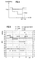
- FIG. 4 illustrates the facts described above at the minimum transmission power limit Pmin analogous to the representation of FIG. 1 , How out FIG. 4 is apparent, the variable Ptrace tracks each Gain factor reset during an already made limit to the value of the minimum transmit power limit Pmin.
- a transition period T is provided according to the invention, in which the increment, with which the transmission power of the mobile station MS is set or regulated, compared to the normal operation is increased. Also in this case, after the transition period T, the step size is reset to the original value.
- the length T of the transition period or the value of the increased step size the above applies FIG. 1 So said at this point to the description too FIG. 1 can be referenced.
- FIG. 6 is analogous to FIG. 3 the overall law is summarized at the minimum transmit power limit Pmin, again with the rows marked with a cross reflecting the advantages of the present invention.
- FIG. 5 analogous to FIG. 2 a possible course of the transmission power P when using the method described above in the range of the minimum transmission power limit Pmin shown.
- FIG. 4 - FIG. 6 apply in the event that the mobile station MS does not allow falling below the minimum transmission power limit Pmin analogous to the case of the maximum transmission power limit Pmax. However, should the mobile station MS allow it to fall below the minimum transmission power limit Pmin in accordance with the power control commands received from the base station BS, including a corresponding scaling of these power control commands, several methods are conceivable:
- variable ptrace could always be set equal to the actual (scaled) transmission power of the mobile station. Although this would not solve the problem of inadvertent transmission power setting described above after leaving the minimum transmission power limit Pmin, the problem would in this case also exist only in a weakened manner.
- variable ptrace could be used to track the transmit power change due to "gain" factor adjustments FIG. 1 and FIG. 4 be used.
- this would have correspondingly more complicated laws than in the FIG. 3 and FIG. 4 shown cases result.
- a basic problem associated with transmit power control is that the power control commands received by the mobile station MS may be subject to errors, with a typical value for the error probability being 4%.
- this could cause the value of the variable Ptrace to be erroneously reduced at the upper transmission power limit Pmax due to a received power control command or at the lower transmission power limit Pmin is increased in such a way that, as a result of this change of the variable Ptrace, the regulation of the transmission power of the mobile station MS proceeds in the same way as in the conventional method in which the variable Ptrace is disregarded.
- An efficient way of avoiding an erroneous change of the variable ptrace is to change the variable ptrace according to the received power control command only if at least two consecutive power control commands require such a change.
- the probability that two consecutive power control commands are erroneous is only 0.16%, so that this approach can significantly reduce the chance of erroneous alteration of the Ptrace variable.
- Even the probability that a faulty pair of consecutive power control commands is contained in 15 consecutive power control commands is only 2.4%, which is a perfectly acceptable value.
- the two options described above can also be applied in principle to the transmission power control of the mobile station MS, so that the transmission power generated by the mobile station is reduced only if at least two successive power control commands or of m power control commands, at least n power control commands require this.
- the variable Ptrace or an unintentional reset of the variable Ptrace in the range of the upper transmit power limit Pmax or the lower transmit power limit Pmin not only the contents of the received power control commands, ie usually their polarity, but also to make an estimate for the accuracy of the received power control commands. This can be done, for example, by evaluating the amplitude of the signal received by the mobile station MS, since, for a power control command, the amplitude of the received signal generally has to lie between an upper and a lower limit value.
- the mobile station MS determines that the received signal for the power control command or the corresponding command has a relatively small amplitude, the mobile station can assume that in this case the command has not been correctly transmitted, at least with a non-negligible probability.
- the mobile station MS For the modification of the variable Ptrace, only those power control commands are then used by the mobile station MS, which have been classified with sufficient probability as correctly received. Thus, even a relatively small number (in extreme cases, a single one) of power control commands judged to be correctly received may cause a corresponding change or reset of the variable ptrace, while power control commands with less reliability in larger numbers are required.
- variable ptrace Another possibility for avoiding an erroneous change of the variable ptrace is not immediately adapting the variable ptrace completely in accordance with the received power control command in the presence of one of the abovementioned conditions or, generally, upon receipt of a corresponding power control command, but initially only partly to the variable ptrace change.
- it may be provided, for example, initially to change the variable Ptrace only by a predefined maximum amount, for example by 6 dB.
- variable Ptrace may first be changed by only half the difference value between the current value of the variable Ptrace and the respective transmission power limit in accordance with the respective received power control command.
- the mobile station MS makes the degree of change of the variable Ptrace dependent on the time duration which has elapsed since the exceeding of the maximum transmission power limit Pmax or undershooting of the minimum transmission power limit Pmin by the variable Ptrace.
- variable Ptrace may also be suitably combined with each other.
Landscapes
- Engineering & Computer Science (AREA)
- Computer Networks & Wireless Communication (AREA)
- Signal Processing (AREA)
- Mobile Radio Communication Systems (AREA)
- Transmitters (AREA)
Claims (24)
- Procédé de régulation de la puissance d'émission dans un système radio,a) un signal d'émission étant émis par un émetteur (MS) par l'intermédiaire d'un canal de transmission,b) le signal d'émission de l'émetteur (MS) étant reçu et évalué par un récepteur (BS) pour produire en fonction de cette évaluation une instruction de régulation de puissance en vue de la régulation de la puissance d'émission de l'émetteur (MS) et pour la transmettre à l'émetteur (MS), etc) la puissance d'émission de l'émetteur (MS) étant réglée avec un certain pas en tenant compte d'une instruction de régulation de puissance reçue et d'une valeur instantanée d'au moins un paramètre qui décrit le rapport d'une part de puissance d'émission d'un canal de commande associé au canal de transmission et d'une part de puissance d'émission de canaux de données associés au canal de transmission, la puissance d'émission de l'émetteur (MS) étant graduée selon un procédé de graduation lorsqu'elle devient égale ou supérieure à une valeur limite maximale (Pmax) ou lorsqu'elle devient égale ou inférieure à une valeur limite minimale (Pmin),caractérisé par le fait que,
si la puissance d'émission redevient inférieure à la valeur limite maximale (Pmax) ou supérieure à la valeur limite minimale (Pmin) suite à une variation du paramètre, on augmente provisoirement, pendant une période de transition (T) déterminée, la vitesse, notamment le pas, avec laquelle ou lequel la puissance d'émission de l'émetteur (MS) est réglée. - Procédé selon la revendication 1,
caractérisé par le fait que
le réglage de la puissance d'émission de l'émetteur (MS) lors du fonctionnement normal s'effectue avec un premier pas déterminé, et
le réglage de la puissance d'émission de l'émetteur (MS) pendant la période de transition (T) s'effectue provisoirement avec un deuxième pas déterminé qui est supérieur au premier pas,
le réglage de la puissance d'émission de l'émetteur (MS) après la période de transition (T) s'effectuant à nouveau avec le premier pas. - Procédé selon la revendication 1 ou 2,
caractérisé par le fait que
la valeur du pas avec laquelle la puissance d'émission de l'émetteur (MS) est réglée pendant la période de transition (T) est choisie en fonction de la valeur du paramètre. - Procédé selon la revendication 3,
caractérisé par le fait que
le pas avec lequel la puissance d'émission de l'émetteur (MS) est réglée pendant la période de transition (T) est d'autant plus augmenté que la variation de puissance d'émission correspondant à une variation du paramètre est grande. - Procédé selon l'une des revendications précédentes,
caractérisé par le fait que
la durée de la période de transition (T) est choisie en fonction de la valeur du paramètre. - Procédé selon la revendication 5,
caractérisé par le fait que
la durée de la période de transition (T) est choisie d'autant plus grande que la variation de puissance d'émission correspondant à une variation du paramètre est grande. - Procédé selon l'une des revendications précédentes,
caractérisé par le fait que
lorsque la puissance d'émission devient égale ou supérieure à la valeur limite maximale (Pmax) ou lorsqu'elle devient égale ou inférieure à la valeur limite minimale (Pmin), on détermine une valeur de puissance d'émission non graduée (Ptrace) correspondant effectivement à une variation du paramètre, et
on tient compte de la valeur de puissance d'émission non graduée (Ptrace) lors du réglage de la puissance d'émission de l'émetteur (MS) à l'étape c) si la puissance d'émission redevient inférieure à la valeur limite maximale (Pmax) ou supérieure à la valeur limite minimale (Pmin) suite à une variation du paramètre. - Procédé selon la revendication 7,
caractérisé par le fait que,
à l'étape c), on règle la puissance d'émission de l'émetteur (MS) sur la valeur de puissance d'émission non graduée (Ptrace) si la puissance d'émission redevient inférieure à la valeur limite maximale (Pmax) ou supérieure à la valeur limite minimale (Pmin) suite à une variation du paramètre. - Procédé selon la revendication 7 ou 8,
caractérisé par le fait que
à l'étape c), on limite la puissance d'émission de l'émetteur (MS) à la valeur limite maximale (Pmax), et
si la puissance d'émission de l'émetteur (MS) doit être encore augmentée suite à une variation du paramètre, on augmente de façon correspondante la valeur de puissance d'émission non graduée (Ptrace) mais on limite encore la puissance d'émission de l'émetteur (MS) à la valeur limite maximale (Pmax). - Procédé selon l'une des revendications 7 à 9,
caractérisé par le fait que
à l'étape c), on limite la puissance d'émission de l'émetteur (MS) à la valeur limite maximale (Pmax), et
si la puissance d'émission de l'émetteur (MS) doit être diminuée suite à une variation du paramètre, on diminue de façon correspondante la valeur de puissance d'émission non graduée (Ptrace) et on règle la puissance d'émission de l'émetteur (MS) au minimum de la valeur limite maximale (Pmax) et de la valeur de puissance d'émission non graduée (Ptrace) ainsi actualisée. - Procédé selon l'une des revendications 7 à 10,
caractérisé par le fait que
à l'étape c), on limite la puissance d'émission de l'émetteur (MS) à la valeur limite minimale (Pmin), et
si la puissance d'émission de l'émetteur (MS) doit être encore diminuée suite à une variation du paramètre, on diminue de façon correspondante la valeur de puissance d'émission non graduée (Ptrace) et on règle encore la puissance d'émission de l'émetteur (MS) à la valeur limite minimale (Pmin). - Procédé selon l'une des revendications 7 à 11,
caractérisé par le fait que
à l'étape c), on limite la puissance d'émission de l'émetteur (MS) à la valeur limite minimale (Pmin), et
si la puissance d'émission de l'émetteur (MS) doit être augmentée suite à une variation du paramètre, on augmente de façon correspondante la valeur de puissance d'émission non graduée (Ptrace) et on règle la puissance d'émission de l'émetteur (MS) au maximum de la valeur limite minimale (Pmin) et de la valeur de puissance d'émission non graduée (Ptrace) ainsi actualisée. - Procédé selon l'une des revendications 7 à 12,
caractérisé par le fait que
la valeur de puissance d'émission non graduée (Ptrace) n'est modifiée conformément à une instruction de régulation de puissance reçue par l'émetteur (MS) que si au moins deux instructions de régulation de puissance successives demandent une modification correspondante de la valeur de puissance d'émission non graduée (Ptrace). - Procédé selon l'une des revendications 7 à 12,
caractérisé par le fait que
la valeur de puissance d'émission non graduée (Ptrace) n'est modifiée conformément à une instruction de régulation de puissance reçue par l'émetteur (MS) que si cette modification est demandée par plusieurs instructions de régulation de puissance dans un groupe de m instructions de régulation de puissance successives. - Procédé selon l'une des revendications 7 à 14,
caractérisé par le fait que
les instructions de régulation de puissance reçues par l'émetteur (MS) sont évaluées pour connaître leur exactitude, et que la valeur de puissance d'émission non graduée (Ptrace) est modifiée conformément à une instruction de régulation de puissance reçue que si la modification de la valeur de puissance d'émission non graduée (Ptrace) a été demandée par un certain nombre d'instructions de régulation de puissance dont l'exactitude a été estimée à chaque fois avec une certaine probabilité minimale. - Procédé selon l'une des revendications 7 à 15,
caractérisé par le fait que,
lors de la réception d'une instruction de régulation de puissance qui entraîne une modification de la valeur de puissance d'émission non graduée (Ptrace), la valeur de puissance d'émission non graduée (Ptrace) n'est d'abord modifiée que partiellement selon l'instruction de régulation de puissance reçue. - Procédé selon la revendication 16,
caractérisé par le fait que,
lors de la réception d'une instruction de régulation de puissance servant à la modification de la valeur de puissance d'émission non graduée (Ptrace), la valeur de puissance d'émission non graduée (Ptrace) n'est d'abord modifiée que d'une certaine valeur. - Procédé selon la revendication 16,
caractérisé par le fait que,
lors de la réception d'une instruction de régulation de puissance servant à la modification de la valeur de puissance d'émission non graduée (Ptrace), la valeur de puissance d'émission non graduée (Ptrace) n'est d'abord modifiée que d'une certaine valeur qui est choisie en fonction de l'écart entre la valeur de puissance d'émission non graduée (Ptrace) et la valeur limite maximale (Pmax) ou la valeur limite minimale (Pmin). - Procédé selon la revendication 16,
caractérisé par le fait que,
lors de la réception d'une instruction de régulation de puissance servant à la modification de la valeur de puissance d'émission non graduée (Ptrace), la valeur de puissance d'émission non graduée (Ptrace) n'est d'abord modifiée que d'une certaine valeur qui est choisie en fonction du temps écoulé depuis que la puissance d'émission est devenue supérieure à la valeur limite maximale (Pmax) ou inférieure à la valeur limite minimale (Pmin). - Procédé selon l'une des revendications précédentes,
caractérisé par le fait que,
lors de la réception d'une instruction de régulation de puissance, la puissance d'émission de l'émetteur (MS) n'est réglée conformément à l'instruction de régulation de puissance reçue que si au moins deux instructions de régulation de puissance successives demandent une modification correspondante de la puissance d'émission ou si, parmi un groupe de m instructions de régulation de puissance successives, un certain nombre des instructions de régulation de puissance demandent une modification correspondante de la puissance d'émission. - Procédé selon l'une des revendications précédentes,
caractérisé par le fait que
le système radio est un système de radiocommunication mobile, notamment un système de radiocommunication mobile UMTS. - Procédé selon l'une des revendications précédentes,
caractérisé par le fait que
le, au moins un, paramètre est un paramètre de pondération qui décrit la pondération de la part de puissance d'émission du canal de commande associé au canal de transmission ou la pondération de la part de puissance d'émission des canaux de données associés au canal de transmission. - Dispositif d'émission pour un système radio,
le dispositif d'émission (MS) étant conçu de telle sorte qu'il reçoit d'un autre dispositif d'émission (BS) des instructions de régulation de puissance pour la régulation de sa propre puissance d'émission et qu'il règle avec un pas déterminé sa propre puissance d'émission en fonction d'une instruction de régulation de puissance reçue et de la valeur instantanée d'au moins un paramètre qui décrit le rapport d'une part de puissance d'émission d'un canal de commande associé au canal de transmission du dispositif d'émission (BS) et d'une part de puissance d'émission de canaux de données associés au canal de transmission,
le dispositif d'émission (MS) graduant la puissance d'émission selon un procédé de graduation déterminé lorsque celle-ci devient égale ou supérieure à une valeur limite maximale (Pmax) prédéterminée ou lorsque celle-ci devient égale ou inférieure à une valeur limite minimale (Pmin) prédéterminée,
caractérisé par le fait que
le dispositif d'émission (MS) est conçu de telle sorte que, si la puissance d'émission redevient inférieure à la valeur limite maximale (Pmax) ou supérieure à la valeur limite minimale (Pmin) suite à une variation du paramètre, le pas avec lequel la puissance d'émission est réglée est provisoirement augmenté pendant une période de transition (T) déterminée. - Dispositif d'émission selon la revendication 23,
caractérisé par le fait que le dispositif d'émission est conçu pour la mise en oeuvre du procédé selon l'une des revendications 2 à 22.
Applications Claiming Priority (3)
| Application Number | Priority Date | Filing Date | Title |
|---|---|---|---|
| DE10048403 | 2000-09-29 | ||
| DE10048403 | 2000-09-29 | ||
| PCT/DE2001/003492 WO2002027965A1 (fr) | 2000-09-29 | 2001-09-11 | Procede de regulation de la puissance d'emission dans un systeme radio, et dispositif d'emission correspondant |
Publications (2)
| Publication Number | Publication Date |
|---|---|
| EP1320946A1 EP1320946A1 (fr) | 2003-06-25 |
| EP1320946B1 true EP1320946B1 (fr) | 2008-06-04 |
Family
ID=7658161
Family Applications (1)
| Application Number | Title | Priority Date | Filing Date |
|---|---|---|---|
| EP01978119A Expired - Lifetime EP1320946B1 (fr) | 2000-09-29 | 2001-09-11 | Procede de regulation de la puissance d'emission dans un systeme radio, et dispositif d'emission correspondant |
Country Status (3)
| Country | Link |
|---|---|
| EP (1) | EP1320946B1 (fr) |
| DE (1) | DE50114013D1 (fr) |
| WO (1) | WO2002027965A1 (fr) |
Families Citing this family (2)
| Publication number | Priority date | Publication date | Assignee | Title |
|---|---|---|---|---|
| US8532691B2 (en) * | 2011-08-03 | 2013-09-10 | Intel Mobile Communications GmbH | Method and device for controlling a transmit power in a radio communications system |
| US10251132B2 (en) * | 2015-07-23 | 2019-04-02 | Acer Incorporated | Device and method of handling uplink power control for unlicensed serving cell |
Family Cites Families (1)
| Publication number | Priority date | Publication date | Assignee | Title |
|---|---|---|---|---|
| US5896411A (en) * | 1997-05-05 | 1999-04-20 | Northern Telecom Limited | Enhanced reverse link power control in a wireless communication system |
-
2001
- 2001-09-11 DE DE50114013T patent/DE50114013D1/de not_active Expired - Lifetime
- 2001-09-11 WO PCT/DE2001/003492 patent/WO2002027965A1/fr not_active Ceased
- 2001-09-11 EP EP01978119A patent/EP1320946B1/fr not_active Expired - Lifetime
Also Published As
| Publication number | Publication date |
|---|---|
| DE50114013D1 (de) | 2008-07-17 |
| WO2002027965A1 (fr) | 2002-04-04 |
| EP1320946A1 (fr) | 2003-06-25 |
Similar Documents
| Publication | Publication Date | Title |
|---|---|---|
| DE69913232T3 (de) | Verfahren und System zur Sendeleistungsregelung während Makrodiversität | |
| EP1501207B1 (fr) | Procédé pour la régulation de la puissance d'émission dans un système radio | |
| DE69934577T2 (de) | Funkkommunikationssystem | |
| DE69625009T2 (de) | Verfahren zur Steuerung der Sendeleistung eines Funksenders | |
| EP1188256B9 (fr) | Procede de reglage de la puissance d'emission dans un systeme radio, et systeme radio correspondant | |
| DE69910413T2 (de) | Basisstation, Mobilstation und Verfahren zur Sendeleistungsregelung | |
| DE19725438B4 (de) | Regelung der Übertragungsleistung bei drahtloser Paket-Datenübertragung | |
| DE60127138T2 (de) | Regelung der Sendeleistung in einem CDMA-basierten System | |
| EP1247352B1 (fr) | Commande de puissance dans des systemes telephoniques mobiles en cas d'interruption de transmission | |
| DE69831014T2 (de) | Vorrichtung und verfahren zur optimierten sendeleistungsregelung | |
| DE69728745T2 (de) | Signal-übertragungsverfahren, mobiles endgerät, und basisstationsgerät für mobiles cdma kommunikationssystem | |
| DE60132848T2 (de) | Verfahren zur Sendeleistungssteuerung in einem Mobilfunkkommunikationssystem | |
| EP1325565A1 (fr) | Procede et dispositif pour lancer une communication | |
| EP1273107B1 (fr) | Procede de reglage de la puissance d'emission dans un systeme de radiocommunication | |
| EP1079542B1 (fr) | Contrôle de la puissance d'émission dans un système de communication mobile | |
| EP1320946B1 (fr) | Procede de regulation de la puissance d'emission dans un systeme radio, et dispositif d'emission correspondant | |
| EP1864397B1 (fr) | Procede pour mettre a l'echelle un canal e-dch | |
| EP1310050B1 (fr) | Procede de reglage de la puissance d'emission dans un systeme radio | |
| EP1290813B1 (fr) | Procede pour reguler la puissance d'emission d'une station d'emission, et station d'emission | |
| EP1995888B1 (fr) | Procédé de commande de la puissance de transmission d'une station radio | |
| DE102007046340A1 (de) | Verfahren und Vorrichtung zum Regeln eines Leistungsverstärkers | |
| DE10237582A1 (de) | Verfahren zur Sendeleistungssteuerung einer Sendestation eines Funkkommunikationssystems, Funkkommunikationssystem, Sendestation sowie Empfangsstation | |
| EP1394961A1 (fr) | Système de communication mobile et procédé de contrôle de puissance d'un émetteur |
Legal Events
| Date | Code | Title | Description |
|---|---|---|---|
| PUAI | Public reference made under article 153(3) epc to a published international application that has entered the european phase |
Free format text: ORIGINAL CODE: 0009012 |
|
| 17P | Request for examination filed |
Effective date: 20030310 |
|
| AK | Designated contracting states |
Designated state(s): AT BE CH CY DE DK ES FI FR GB GR IE IT LI LU MC NL PT SE TR |
|
| RBV | Designated contracting states (corrected) |
Designated state(s): DE FR GB |
|
| GRAP | Despatch of communication of intention to grant a patent |
Free format text: ORIGINAL CODE: EPIDOSNIGR1 |
|
| GRAS | Grant fee paid |
Free format text: ORIGINAL CODE: EPIDOSNIGR3 |
|
| GRAA | (expected) grant |
Free format text: ORIGINAL CODE: 0009210 |
|
| AK | Designated contracting states |
Kind code of ref document: B1 Designated state(s): DE FR GB |
|
| REG | Reference to a national code |
Ref country code: GB Ref legal event code: FG4D Free format text: NOT ENGLISH |
|
| REF | Corresponds to: |
Ref document number: 50114013 Country of ref document: DE Date of ref document: 20080717 Kind code of ref document: P |
|
| RAP2 | Party data changed (patent owner data changed or rights of a patent transferred) |
Owner name: PALM, INC. |
|
| PLBE | No opposition filed within time limit |
Free format text: ORIGINAL CODE: 0009261 |
|
| STAA | Information on the status of an ep patent application or granted ep patent |
Free format text: STATUS: NO OPPOSITION FILED WITHIN TIME LIMIT |
|
| 26N | No opposition filed |
Effective date: 20090305 |
|
| REG | Reference to a national code |
Ref country code: GB Ref legal event code: 732E Free format text: REGISTERED BETWEEN 20100826 AND 20100901 |
|
| REG | Reference to a national code |
Ref country code: GB Ref legal event code: 732E Free format text: REGISTERED BETWEEN 20110407 AND 20110413 |
|
| REG | Reference to a national code |
Ref country code: DE Ref legal event code: R081 Ref document number: 50114013 Country of ref document: DE Owner name: QUALCOMM INCORPORATED, SAN DIEGO, US Free format text: FORMER OWNER: PALM, INC. (N.D.GES. D. STAATES DELAWARE), SUNNYVALE, CALIF., US Effective date: 20110406 |
|
| REG | Reference to a national code |
Ref country code: FR Ref legal event code: TP Owner name: HEWLETT PACKARD DEVELOPMENT COMPANY, L.P., US Effective date: 20120731 |
|
| REG | Reference to a national code |
Ref country code: DE Ref legal event code: R082 Ref document number: 50114013 Country of ref document: DE Representative=s name: SAMSON & PARTNER, PATENTANWAELTE, DE |
|
| REG | Reference to a national code |
Ref country code: DE Ref legal event code: R082 Ref document number: 50114013 Country of ref document: DE Representative=s name: MAUCHER JENKINS, DE Effective date: 20140307 Ref country code: DE Ref legal event code: R081 Ref document number: 50114013 Country of ref document: DE Owner name: QUALCOMM INCORPORATED, US Free format text: FORMER OWNER: HEWLETT-PACKARD DEVELOPMENT CO., L.P., HOUSTON, US Effective date: 20140307 Ref country code: DE Ref legal event code: R082 Ref document number: 50114013 Country of ref document: DE Representative=s name: SAMSON & PARTNER, PATENTANWAELTE, DE Effective date: 20140307 Ref country code: DE Ref legal event code: R081 Ref document number: 50114013 Country of ref document: DE Owner name: QUALCOMM INCORPORATED, SAN DIEGO, US Free format text: FORMER OWNER: HEWLETT-PACKARD DEVELOPMENT COMPANY, L.P., HOUSTON, TEX., US Effective date: 20140307 Ref country code: DE Ref legal event code: R082 Ref document number: 50114013 Country of ref document: DE Representative=s name: SAMSON & PARTNER PATENTANWAELTE MBB, DE Effective date: 20140307 Ref country code: DE Ref legal event code: R082 Ref document number: 50114013 Country of ref document: DE Representative=s name: MAUCHER JENKINS PATENTANWAELTE & RECHTSANWAELT, DE Effective date: 20140307 |
|
| REG | Reference to a national code |
Ref country code: GB Ref legal event code: 732E Free format text: REGISTERED BETWEEN 20140508 AND 20140514 |
|
| REG | Reference to a national code |
Ref country code: FR Ref legal event code: TP Owner name: QUALCOMM INCORPORATED, US Effective date: 20140624 |
|
| REG | Reference to a national code |
Ref country code: FR Ref legal event code: PLFP Year of fee payment: 16 |
|
| REG | Reference to a national code |
Ref country code: DE Ref legal event code: R082 Ref document number: 50114013 Country of ref document: DE Representative=s name: MAUCHER JENKINS, DE Ref country code: DE Ref legal event code: R082 Ref document number: 50114013 Country of ref document: DE Representative=s name: MAUCHER JENKINS PATENTANWAELTE & RECHTSANWAELT, DE |
|
| REG | Reference to a national code |
Ref country code: FR Ref legal event code: PLFP Year of fee payment: 17 |
|
| REG | Reference to a national code |
Ref country code: FR Ref legal event code: PLFP Year of fee payment: 18 |
|
| PGFP | Annual fee paid to national office [announced via postgrant information from national office to epo] |
Ref country code: DE Payment date: 20180815 Year of fee payment: 18 Ref country code: FR Payment date: 20180817 Year of fee payment: 18 |
|
| PGFP | Annual fee paid to national office [announced via postgrant information from national office to epo] |
Ref country code: GB Payment date: 20180828 Year of fee payment: 18 |
|
| REG | Reference to a national code |
Ref country code: DE Ref legal event code: R119 Ref document number: 50114013 Country of ref document: DE |
|
| PG25 | Lapsed in a contracting state [announced via postgrant information from national office to epo] |
Ref country code: DE Free format text: LAPSE BECAUSE OF NON-PAYMENT OF DUE FEES Effective date: 20200401 |
|
| GBPC | Gb: european patent ceased through non-payment of renewal fee |
Effective date: 20190911 |
|
| PG25 | Lapsed in a contracting state [announced via postgrant information from national office to epo] |
Ref country code: FR Free format text: LAPSE BECAUSE OF NON-PAYMENT OF DUE FEES Effective date: 20190930 Ref country code: GB Free format text: LAPSE BECAUSE OF NON-PAYMENT OF DUE FEES Effective date: 20190911 |