EP1321014B1 - Dispositif de production d'un plasma, procede d'ionisation, utilisations du procede et realisations mettant en oeuvre le dispositif selon l'invention - Google Patents
Dispositif de production d'un plasma, procede d'ionisation, utilisations du procede et realisations mettant en oeuvre le dispositif selon l'invention Download PDFInfo
- Publication number
- EP1321014B1 EP1321014B1 EP01972176A EP01972176A EP1321014B1 EP 1321014 B1 EP1321014 B1 EP 1321014B1 EP 01972176 A EP01972176 A EP 01972176A EP 01972176 A EP01972176 A EP 01972176A EP 1321014 B1 EP1321014 B1 EP 1321014B1
- Authority
- EP
- European Patent Office
- Prior art keywords
- chamber
- resonance chamber
- pipes
- elongated pipe
- opening
- Prior art date
- Legal status (The legal status is an assumption and is not a legal conclusion. Google has not performed a legal analysis and makes no representation as to the accuracy of the status listed.)
- Expired - Lifetime
Links
- 238000000034 method Methods 0.000 title claims description 23
- 238000004519 manufacturing process Methods 0.000 title claims description 16
- 238000000752 ionisation method Methods 0.000 title description 2
- 238000002485 combustion reaction Methods 0.000 claims description 48
- 239000000126 substance Substances 0.000 claims description 46
- 230000033001 locomotion Effects 0.000 claims description 44
- 238000006243 chemical reaction Methods 0.000 claims description 33
- 230000001143 conditioned effect Effects 0.000 claims description 25
- 230000003750 conditioning effect Effects 0.000 claims description 19
- 230000001133 acceleration Effects 0.000 claims description 16
- 230000008569 process Effects 0.000 claims description 15
- 239000002699 waste material Substances 0.000 claims description 15
- 230000001427 coherent effect Effects 0.000 claims description 14
- 230000003068 static effect Effects 0.000 claims description 13
- 230000009466 transformation Effects 0.000 claims description 12
- 230000004087 circulation Effects 0.000 claims description 10
- 238000009833 condensation Methods 0.000 claims description 10
- 230000005494 condensation Effects 0.000 claims description 10
- 238000001816 cooling Methods 0.000 claims description 10
- 238000010438 heat treatment Methods 0.000 claims description 10
- 239000007787 solid Substances 0.000 claims description 10
- 239000000203 mixture Substances 0.000 claims description 8
- 238000003756 stirring Methods 0.000 claims description 8
- 230000004907 flux Effects 0.000 claims description 7
- 235000014676 Phragmites communis Nutrition 0.000 claims description 5
- 230000007423 decrease Effects 0.000 claims description 5
- 239000000779 smoke Substances 0.000 claims description 4
- 238000006073 displacement reaction Methods 0.000 claims description 3
- 238000013459 approach Methods 0.000 claims description 2
- 230000033228 biological regulation Effects 0.000 claims description 2
- 238000007664 blowing Methods 0.000 claims 1
- 230000013011 mating Effects 0.000 claims 1
- 239000000463 material Substances 0.000 description 140
- 239000003570 air Substances 0.000 description 124
- 230000008602 contraction Effects 0.000 description 33
- 230000000694 effects Effects 0.000 description 25
- 239000007789 gas Substances 0.000 description 21
- 239000002245 particle Substances 0.000 description 18
- 239000000446 fuel Substances 0.000 description 17
- 239000007788 liquid Substances 0.000 description 13
- MWUXSHHQAYIFBG-UHFFFAOYSA-N nitrogen oxide Inorganic materials O=[N] MWUXSHHQAYIFBG-UHFFFAOYSA-N 0.000 description 12
- 238000002347 injection Methods 0.000 description 11
- 239000007924 injection Substances 0.000 description 11
- 230000010349 pulsation Effects 0.000 description 10
- 210000001015 abdomen Anatomy 0.000 description 9
- 230000006870 function Effects 0.000 description 9
- 238000012546 transfer Methods 0.000 description 9
- 230000002787 reinforcement Effects 0.000 description 8
- 239000011248 coating agent Substances 0.000 description 7
- 238000000576 coating method Methods 0.000 description 7
- 230000000670 limiting effect Effects 0.000 description 7
- 238000007254 oxidation reaction Methods 0.000 description 7
- 235000002918 Fraxinus excelsior Nutrition 0.000 description 6
- 239000002956 ash Substances 0.000 description 6
- 230000010339 dilation Effects 0.000 description 6
- 239000000295 fuel oil Substances 0.000 description 6
- 238000002156 mixing Methods 0.000 description 6
- 230000003647 oxidation Effects 0.000 description 6
- 239000004033 plastic Substances 0.000 description 6
- 229920003023 plastic Polymers 0.000 description 6
- 239000002023 wood Substances 0.000 description 6
- UFHFLCQGNIYNRP-UHFFFAOYSA-N Hydrogen Chemical compound [H][H] UFHFLCQGNIYNRP-UHFFFAOYSA-N 0.000 description 5
- 238000010494 dissociation reaction Methods 0.000 description 5
- 230000005593 dissociations Effects 0.000 description 5
- 238000001556 precipitation Methods 0.000 description 5
- 230000002829 reductive effect Effects 0.000 description 5
- 229920006395 saturated elastomer Polymers 0.000 description 5
- 230000000295 complement effect Effects 0.000 description 4
- 239000012530 fluid Substances 0.000 description 4
- 239000003517 fume Substances 0.000 description 4
- 239000001257 hydrogen Substances 0.000 description 4
- 229910052739 hydrogen Inorganic materials 0.000 description 4
- 238000011068 loading method Methods 0.000 description 4
- 230000001105 regulatory effect Effects 0.000 description 4
- 230000009471 action Effects 0.000 description 3
- 238000013019 agitation Methods 0.000 description 3
- QVGXLLKOCUKJST-UHFFFAOYSA-N atomic oxygen Chemical compound [O] QVGXLLKOCUKJST-UHFFFAOYSA-N 0.000 description 3
- 230000008901 benefit Effects 0.000 description 3
- 230000006835 compression Effects 0.000 description 3
- 238000007906 compression Methods 0.000 description 3
- 230000001276 controlling effect Effects 0.000 description 3
- 230000007547 defect Effects 0.000 description 3
- 230000001066 destructive effect Effects 0.000 description 3
- 239000010791 domestic waste Substances 0.000 description 3
- 238000002663 nebulization Methods 0.000 description 3
- 239000006199 nebulizer Substances 0.000 description 3
- 239000003921 oil Substances 0.000 description 3
- 230000010355 oscillation Effects 0.000 description 3
- 239000001301 oxygen Substances 0.000 description 3
- 229910052760 oxygen Inorganic materials 0.000 description 3
- 230000036961 partial effect Effects 0.000 description 3
- 230000000149 penetrating effect Effects 0.000 description 3
- 230000005855 radiation Effects 0.000 description 3
- 230000009467 reduction Effects 0.000 description 3
- 238000010992 reflux Methods 0.000 description 3
- 239000007858 starting material Substances 0.000 description 3
- 239000000725 suspension Substances 0.000 description 3
- 239000010913 used oil Substances 0.000 description 3
- XLYOFNOQVPJJNP-UHFFFAOYSA-N water Substances O XLYOFNOQVPJJNP-UHFFFAOYSA-N 0.000 description 3
- OKTJSMMVPCPJKN-UHFFFAOYSA-N Carbon Chemical compound [C] OKTJSMMVPCPJKN-UHFFFAOYSA-N 0.000 description 2
- UGFAIRIUMAVXCW-UHFFFAOYSA-N Carbon monoxide Chemical compound [O+]#[C-] UGFAIRIUMAVXCW-UHFFFAOYSA-N 0.000 description 2
- 229910052799 carbon Inorganic materials 0.000 description 2
- 210000000078 claw Anatomy 0.000 description 2
- 238000004891 communication Methods 0.000 description 2
- 230000008878 coupling Effects 0.000 description 2
- 238000010168 coupling process Methods 0.000 description 2
- 238000005859 coupling reaction Methods 0.000 description 2
- 239000013078 crystal Substances 0.000 description 2
- 238000002425 crystallisation Methods 0.000 description 2
- 230000008025 crystallization Effects 0.000 description 2
- 230000006735 deficit Effects 0.000 description 2
- 238000011161 development Methods 0.000 description 2
- 238000007599 discharging Methods 0.000 description 2
- 238000004880 explosion Methods 0.000 description 2
- 239000003546 flue gas Substances 0.000 description 2
- 230000003993 interaction Effects 0.000 description 2
- 238000012423 maintenance Methods 0.000 description 2
- 238000002844 melting Methods 0.000 description 2
- 230000008018 melting Effects 0.000 description 2
- 239000002184 metal Substances 0.000 description 2
- 239000003595 mist Substances 0.000 description 2
- 238000012986 modification Methods 0.000 description 2
- 230000004048 modification Effects 0.000 description 2
- 239000000123 paper Substances 0.000 description 2
- 238000007639 printing Methods 0.000 description 2
- 238000012545 processing Methods 0.000 description 2
- 230000001681 protective effect Effects 0.000 description 2
- 230000002441 reversible effect Effects 0.000 description 2
- 239000004576 sand Substances 0.000 description 2
- 239000011343 solid material Substances 0.000 description 2
- 239000002910 solid waste Substances 0.000 description 2
- 230000006641 stabilisation Effects 0.000 description 2
- 238000011105 stabilization Methods 0.000 description 2
- XMWRBQBLMFGWIX-UHFFFAOYSA-N C60 fullerene Chemical compound C12=C3C(C4=C56)=C7C8=C5C5=C9C%10=C6C6=C4C1=C1C4=C6C6=C%10C%10=C9C9=C%11C5=C8C5=C8C7=C3C3=C7C2=C1C1=C2C4=C6C4=C%10C6=C9C9=C%11C5=C5C8=C3C3=C7C1=C1C2=C4C6=C2C9=C5C3=C12 XMWRBQBLMFGWIX-UHFFFAOYSA-N 0.000 description 1
- 206010013457 Dissociation Diseases 0.000 description 1
- 206010021143 Hypoxia Diseases 0.000 description 1
- 238000005411 Van der Waals force Methods 0.000 description 1
- 206010000210 abortion Diseases 0.000 description 1
- 231100000176 abortion Toxicity 0.000 description 1
- 238000010521 absorption reaction Methods 0.000 description 1
- 238000009825 accumulation Methods 0.000 description 1
- 230000004913 activation Effects 0.000 description 1
- 230000006978 adaptation Effects 0.000 description 1
- 239000000443 aerosol Substances 0.000 description 1
- 239000012080 ambient air Substances 0.000 description 1
- 238000010009 beating Methods 0.000 description 1
- 230000015572 biosynthetic process Effects 0.000 description 1
- 230000000903 blocking effect Effects 0.000 description 1
- 230000008859 change Effects 0.000 description 1
- 239000003153 chemical reaction reagent Substances 0.000 description 1
- 239000013626 chemical specie Substances 0.000 description 1
- 238000004140 cleaning Methods 0.000 description 1
- 238000004590 computer program Methods 0.000 description 1
- 230000001595 contractor effect Effects 0.000 description 1
- 238000012937 correction Methods 0.000 description 1
- 125000004122 cyclic group Chemical group 0.000 description 1
- 230000006378 damage Effects 0.000 description 1
- 238000013016 damping Methods 0.000 description 1
- 230000003111 delayed effect Effects 0.000 description 1
- 238000000151 deposition Methods 0.000 description 1
- 230000008021 deposition Effects 0.000 description 1
- 238000009795 derivation Methods 0.000 description 1
- 239000010432 diamond Substances 0.000 description 1
- 230000008034 disappearance Effects 0.000 description 1
- 208000037265 diseases, disorders, signs and symptoms Diseases 0.000 description 1
- 208000018459 dissociative disease Diseases 0.000 description 1
- 238000000605 extraction Methods 0.000 description 1
- 230000002349 favourable effect Effects 0.000 description 1
- 238000010304 firing Methods 0.000 description 1
- 235000013305 food Nutrition 0.000 description 1
- 229910003472 fullerene Inorganic materials 0.000 description 1
- 239000010763 heavy fuel oil Substances 0.000 description 1
- 229930195733 hydrocarbon Natural products 0.000 description 1
- 150000002430 hydrocarbons Chemical class 0.000 description 1
- 150000002431 hydrogen Chemical class 0.000 description 1
- 125000004435 hydrogen atom Chemical group [H]* 0.000 description 1
- 230000000977 initiatory effect Effects 0.000 description 1
- 238000009434 installation Methods 0.000 description 1
- 230000001788 irregular Effects 0.000 description 1
- 239000004973 liquid crystal related substance Substances 0.000 description 1
- 239000010808 liquid waste Substances 0.000 description 1
- 239000000155 melt Substances 0.000 description 1
- 239000012764 mineral filler Substances 0.000 description 1
- 238000012544 monitoring process Methods 0.000 description 1
- 230000008520 organization Effects 0.000 description 1
- 230000003534 oscillatory effect Effects 0.000 description 1
- 239000007800 oxidant agent Substances 0.000 description 1
- 230000001590 oxidative effect Effects 0.000 description 1
- 230000002093 peripheral effect Effects 0.000 description 1
- 230000002028 premature Effects 0.000 description 1
- 238000002360 preparation method Methods 0.000 description 1
- 230000000750 progressive effect Effects 0.000 description 1
- TURAMGVWNUTQKH-UHFFFAOYSA-N propa-1,2-dien-1-one Chemical compound C=C=C=O TURAMGVWNUTQKH-UHFFFAOYSA-N 0.000 description 1
- 239000003380 propellant Substances 0.000 description 1
- 239000012429 reaction media Substances 0.000 description 1
- 230000003134 recirculating effect Effects 0.000 description 1
- 238000002407 reforming Methods 0.000 description 1
- 230000000717 retained effect Effects 0.000 description 1
- 238000005096 rolling process Methods 0.000 description 1
- 239000010801 sewage sludge Substances 0.000 description 1
- 230000035939 shock Effects 0.000 description 1
- 239000004449 solid propellant Substances 0.000 description 1
- 239000000243 solution Substances 0.000 description 1
- 238000005507 spraying Methods 0.000 description 1
- 238000004544 sputter deposition Methods 0.000 description 1
- 230000005654 stationary process Effects 0.000 description 1
- 238000006467 substitution reaction Methods 0.000 description 1
- 230000000153 supplemental effect Effects 0.000 description 1
- 230000001360 synchronised effect Effects 0.000 description 1
- 230000032258 transport Effects 0.000 description 1
- 239000011800 void material Substances 0.000 description 1
Images


Classifications
-
- F—MECHANICAL ENGINEERING; LIGHTING; HEATING; WEAPONS; BLASTING
- F23—COMBUSTION APPARATUS; COMBUSTION PROCESSES
- F23C—METHODS OR APPARATUS FOR COMBUSTION USING FLUID FUEL OR SOLID FUEL SUSPENDED IN A CARRIER GAS OR AIR
- F23C99/00—Subject-matter not provided for in other groups of this subclass
- F23C99/003—Combustion process using sound or vibrations
-
- B—PERFORMING OPERATIONS; TRANSPORTING
- B01—PHYSICAL OR CHEMICAL PROCESSES OR APPARATUS IN GENERAL
- B01J—CHEMICAL OR PHYSICAL PROCESSES, e.g. CATALYSIS OR COLLOID CHEMISTRY; THEIR RELEVANT APPARATUS
- B01J19/00—Chemical, physical or physico-chemical processes in general; Their relevant apparatus
- B01J19/008—Processes for carrying out reactions under cavitation conditions
-
- F—MECHANICAL ENGINEERING; LIGHTING; HEATING; WEAPONS; BLASTING
- F02—COMBUSTION ENGINES; HOT-GAS OR COMBUSTION-PRODUCT ENGINE PLANTS
- F02M—SUPPLYING COMBUSTION ENGINES IN GENERAL WITH COMBUSTIBLE MIXTURES OR CONSTITUENTS THEREOF
- F02M27/00—Apparatus for treating combustion-air, fuel, or fuel-air mixture, by catalysts, electric means, magnetism, rays, sound waves, or the like
- F02M27/04—Apparatus for treating combustion-air, fuel, or fuel-air mixture, by catalysts, electric means, magnetism, rays, sound waves, or the like by electric means, ionisation, polarisation or magnetism
- F02M27/042—Apparatus for treating combustion-air, fuel, or fuel-air mixture, by catalysts, electric means, magnetism, rays, sound waves, or the like by electric means, ionisation, polarisation or magnetism by plasma
-
- H—ELECTRICITY
- H05—ELECTRIC TECHNIQUES NOT OTHERWISE PROVIDED FOR
- H05H—PLASMA TECHNIQUE; PRODUCTION OF ACCELERATED ELECTRICALLY-CHARGED PARTICLES OR OF NEUTRONS; PRODUCTION OR ACCELERATION OF NEUTRAL MOLECULAR OR ATOMIC BEAMS
- H05H1/00—Generating plasma; Handling plasma
- H05H1/24—Generating plasma
- H05H1/2475—Generating plasma using acoustic pressure discharges
-
- B—PERFORMING OPERATIONS; TRANSPORTING
- B01—PHYSICAL OR CHEMICAL PROCESSES OR APPARATUS IN GENERAL
- B01J—CHEMICAL OR PHYSICAL PROCESSES, e.g. CATALYSIS OR COLLOID CHEMISTRY; THEIR RELEVANT APPARATUS
- B01J2219/00—Chemical, physical or physico-chemical processes in general; Their relevant apparatus
- B01J2219/08—Processes employing the direct application of electric or wave energy, or particle radiation; Apparatus therefor
- B01J2219/0894—Processes carried out in the presence of a plasma
- B01J2219/0898—Hot plasma
Definitions
- the present invention relates to the field of the transformation of the material and relates to a device for producing a plasma from a combustion reaction of a material or a mixture of materials M, an ionization process or of transformation of the material using this device, uses of the method according to the invention as well as embodiments using the device according to the invention.
- Static devices subjected to the pulsations of the flue gas ducts that generate beat-downs in the combustion chambers produce a lot of unburned residues. So, he It is common to clog a flue in three weeks of use.
- the power torque of the thermal engines whose efficiency is low compared to the energy capacities of the fuels drops rapidly when the mechanical speed exceeds a certain correlation threshold with the speed of reaction, which is characterized by the propagation of the flame front. It is then necessary to use fuels with improved kinetic rates, which in turn increases the production of nitrogen oxides and this, in proportion to the combustion temperature.
- the problem encountered in the context of the present invention results from the actual thermal agitation procedure which further maintains the inconsistency of the reaction medium that the thermodynamic conditions are far from the standard state. Therefore, the breaks in fuel molecules and their behavior of free particles is totally random.
- the flame front is the only coherent fringe in the agitated medium of the reaction.
- the propagation of the latter in a Brownian medium supposes a movement of coherence organization which precedes it and a movement of decoherence which follows it, which are generators of turbulences which are as much energy of lost motion.
- the heart of the problem lies in the extent of the margin of coherence between the vibratory properties proper of the reacted material and the pulsating and turbulent phenomena independently developed by the reactors.
- the ideal solution lies in the realization of a reactor with consistent, constant, well-controlled and well-controlled pulsating properties in harmony or harmony of the organized and coherent vibratory behavior of the material during the continuity of its transformation, all mainly in the process of encounter. reagents.
- the document WO 96/23400 A2 discloses a device and method for concentrating energy to produce high velocity, pressure and temperature conditions within a container having a resonance chamber.
- the necessary energy that can lead to melting conditions is provided by vibratory waves from sonic transducers.
- the object of the present invention is to provide shaped devices for implementing the properties of stationary flows conveying an acoustic condition so as to construct a reaction system in which all the free particles adopt a coherent behavior subject to the laws of acoustics.
- the means of the present invention aim to develop the Van der Waals interaction forces which reduce the gravitational effects at the time of the dissociations of the material so that their harmonic conditioning and coherent becomes possible.
- the devices according to the present invention have the function of creating, on the one hand, the conditions of coherence and orientation for which dissociated or semi-dissociated species are made to constitute a coherent, oriented and stationary macroscopic field of matter comprising phases of strong condensations followed by dilations (condensations of BOSE EINSTEIN), on the other hand, to create the conditions of durability of the field thus conditioned by the addition of one or other fields in opposition of phase, compensating of the state out of thermodynamic equilibrium, the sum of the movements of the whole then contributing to the formation of a soliton wave having the required conservation properties due to low damping.
- the present invention also allows a simple implementation allowing the use of industrial size reactors because of the length of the flame and its isotropy, and can thus be applied to large furnaces.
- the absence of oxidation products due to the total ionization is a positive consequence for the environment, an advantage which makes it possible to treat, in a harmless and economically profitable manner, practically without limitation, many solid or liquid wastes without we are therefore limited to these.
- the present invention is intended to overcome the aforementioned drawbacks.
- the present invention relates to a device for producing a plasma from a combustion reaction of a material or a mixture of materials M, according to claim 1.
- the invention also relates to a method of ionization or material transformation using a device according to the invention, as claimed in claim 40.
- Another subject of the present invention is various uses of the method as well as different objects implementing the device according to the invention.
- the resonance chamber 1 consists of an elongated cylindrical volume, at the ends generating reflections such as a cavity of "Fabry-Perot".
- This resonance chamber 1 is shaped to favor the stationary circulations reflected by a saturated flow of material (s) M in suspension, conditioned (s), as well as to maintain longitudinal vibrations reinforced by the assistance of the orifice 6 connecting said resonance chamber 1 with the acoustic chamber 5.
- the materials M to be packaged enter the resonance chamber 1 by one or more supply means 2 and come out conditioned for the following reaction via at least one outlet 3, for example an outlet 3 made in the form of a collar.
- the supply means (s) 2 in material (s) M of the resonance chamber 1 consist of at least one supply opening 13 made in said resonance chamber 1. An opening towards the bottom of the resonance chamber 1 or on the bottom itself, allows to enter or inject M materials as they are solid, liquid or gaseous. The different embodiments of the supply means 2 will be described later.
- conditioned materials leave the resonance chamber 1 through a single outlet 3 in the form of an elongated pipe 4 open at both ends thereof to form a resonator neck.
- This elongate pipe 4 has a reduced section relative to the section of the resonance chamber 1, so that the ratio of the sections (impedance factor) remains dimensioned to facilitate a double flow generated, in a sense by the pulsating suction member 10 and, in counter-pressure by the depression, that said pulsating suction member 10 creates in said resonance chamber 1.
- the length of the elongate conduit (s) 4 is a function of the provisions for adjusting the distance between the one or more ends 4 'of said elongate conduit (s) 4 and the first opening 8' of the soliton chamber 8 in which it (s) ) opens (nt) freely, or the conformation of the pulsating suction member 10, provided that the latter resonates in half wavelength.
- the elongated pipe (s) 4 are of adjustable lengths, for example being made in the form of telescopic sections.
- Other means of adapting the length of said elongated conduit (s) 4 are also possible, for example sections connected by extensible bellows. Such sections may in particular facilitate the start-up of the general device according to the invention, serve to refine the settings parameters or the rapid cleaning of the elongate pipe or lines 4 during operation of said device.
- the section of the elongated pipe (s) 4 is smaller than that of the resonance chamber 1 and greater than that of a first opening 8 'of the soliton chamber 8 which is connected to the pulsating suction member 10, so that the material flow M, which tends to have the section of said first opening 8 ', leaves at least one annular space for introduction into the elongated pipe or conduits 4 of the reflected wave constituted by the air introduced by at least one air inlet 9 into the soliton chamber 8, which air rises in said elongated pipe (s) 4 in the direction of the resonance chamber 1.
- the natural frequency of the elongate conduit (s) 4 is chosen so that it resonates on the fundamental frequency of the circulating wave in the resonance chamber 1 and in such a way that the wave directed reflection of the output of the elongated conduit (s) 4 to the resonant chamber 1 comes form a common mode with the incident wave to promote the beat.
- the acoustic chamber 5 consists of an acoustic resonance volume sealingly connected by an orifice 6 to the chamber resonance 1 and provided on the opposite side to this orifice 6 of an adjustable acoustic device 7.
- the acoustic device 7 is an acoustic nozzle or an acoustic reed, for example a device of the variable opening flute type or a free reed device whose free space is adjustable.
- this acoustic chamber 5 are adapted to the device that it equips or to its implementation subject to the distance between the nip at the orifice 6 and the acoustic member 7, factor n th of the harmonics of the pulsations, tuned to the distance between the outlet (s) 3 and the acoustic member 7.
- the dimensions and the shape of the acoustic chamber 5 are a function of the distance between said orifice 6 and said acoustic device 7, this distance being itself given to the distance between the output (s). 3 of said resonance chamber 1 and said acoustic device 7.
- the distance between said orifice 6 and said acoustic device 7 is an entire submultiple of the distance between the outlet (s) 3 of said resonance chamber 1 and said acoustic device 7.
- the orifice 6, the acoustic device 7 and an output 3 of the resonance chamber 1 are aligned.
- soliton chamber 8 is located between the pulsating suction element 10 and the outlet 3 of the resonance chamber 1.
- the soliton chamber 8 has a cylindrical or quasi-cylindrical shape 27 having a first opening 8 'for connection to the pulsating suction element 10 and a second opening 8 "fitting on the or the elongated conduits 4 of the resonance chamber 1 so that the space remaining between said second opening 8 "and said elongate conduit (s) 4 forms at least one air inlet 9 for said soliton chamber 8.
- the soliton chamber 8 has substantially a bell-shaped bell shape 28 comprising, on the one hand, a first opening 8 'on the bulge side intended for the connection to the pulsating suction member 10 and, secondly, a second opening 8 "more or less curved fitting on the elongated pipe (s) 4 of the resonance chamber 1 so that the space remaining between said second opening 8 "and said elongated conduit (s) 4 forms at least one air inlet 9 for said soliton chamber 8.
- the second opening 8 "of the soliton chamber 8 is extended on the side of the elongate pipe or pipes 4, by a sleeve 29 of section greater than that of the elongated pipe or conduits 4 and of length equal to half the length of the elongate conduit (s) 4, said sleeve 29 being fixedly positioned on the free end of said elongate conduit (s) 4, the free space between said sleeve 29 and said conduit (s) 4 forming at least one air inlet 9 for said soliton chamber 8.
- the second opening 8 "of the soliton chamber 8 is extended on the side of the elongate pipe (s) 4, by a sleeve 29 of section greater than that of the elongate pipe (s) 4 and of length equal to half of the length of the elongate pipe or pipes 4, said sleeve 29 being movably positioned on the free end of said elongated pipe or conduits 4, the free space between said sleeve 29 and said elongated pipe or conduits 4 forming at at least one air inlet 9 for said soliton chamber 8 and the second opening 8 "more or less curved of the soliton chamber 8 sliding frictionally on said sleeve 29.
- the soliton chamber 8 is movable relative to the resonance chamber 1.
- the pulsating suction member 10 is thus movable relative to the soliton chamber 8, the space between said soliton chamber 8 and said pulsating suction member 10 forming part of a flow accelerator device 30 with variable opening.
- the device according to the invention is further characterized in that the resonance chamber 1, the soliton chamber 8 and / or the pulsating suction member 10 are mounted on one or several carriages 31 which move along at least one rail 32.
- the device according to the invention comprises a means for forming a rotary, tangential oriented, rotary suction movement generating a toroidal acceleration of the flow passing through the flow accelerating device 30.
- the elongate pipe (s) 4 of the resonance chamber 1 have, on their outer peripheries, elements 33 having an external surface which increases in the direction of the resonance chamber 1, so that the space existing between the walls of the the second opening 8 "or those of its extension by the sleeve 29 and the outer surface of said elements 33 decreases when said second opening 8" or said sleeve 29 approaches said elements 33, thereby regulating the air flow entering the air inlets 9.
- the outer surface of the elements 33 is of complementary shape to that of the second opening 8 "more or less curved or that of the sleeve 29.
- the elements 33 are movably mounted on the elongated pipe (s) 4, for example, by sliding or rotation around a helical screw.
- the depth of the interlocking of the second opening 8 ", possibly extended by the sleeve 29, on the elongated pipe (s) 4 is adjustable by means of the displacement of the soliton chamber 8, the sleeve 29 and / or the elements 33, in order to control the ionization reaction of the material or materials M variation of the depth of said interlocking to adapt the phase condition of the incoming air by the air inlets 9, so that said flow of the air is in phase opposition with respect to the material flow M extracted from the resonance chamber 1.
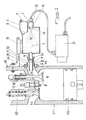
- FIG. 1 of the accompanying drawings represents a nonlimiting example of a simplified embodiment of a device according to the invention, in which the ovoid shaped soliton chamber 8 has a first opening 8 '(bulge side) which is intended for the sealed connection of said chamber to solitons 8 to the pulsating suction member 10 and a second opening 8 "(tapered side) located opposite the first opening 8 '.
- the soliton chamber 8 illustrated is connected to the outside atmosphere by one or more air inlets 9 and has two main functions namely, on the one hand, that of receiving the output 3 of the resonance chamber 1 which penetrates more or less deeply, through the elongated pipe 4, inside the soliton chamber 8, the adjustment of the distance between the outlet 3 (or the end 4 'of the elongated pipe 4) and the first opening 8 'of said soliton chamber 8 for adjusting and controlling the reaction by adjusting the position of the carriage 31 on the rail 32 and, on the other hand, with the air inlets 9 to enter a air flow in phase opposition condition with respect to the flow extracted from the resonance chamber 1.
- the soliton chamber 8 is shaped in such a way that the adjustable inlet of the air inlets 9 is imperatively and immovably located at a nodal plane of the device such as, for example, a nodal plane of the elongated pipe. 4 resonant in half wavelength, one of the nodal planes of one of the resonance chambers 1 or acoustic 5, etc.
- the air inlet 9 through the second opening 8 "of the soliton chamber 8 is supplied in leaktight manner by at least one pipe which originates at one of the nodal points of the device.
- the amount of air that enters the soliton chamber 8 through the air inlet 9 must allow the recirculation "soliton" through the elongated pipe 4 to compensate and control the depression in the resonance chamber 1 .
- the rail 32 supports the carriage 31, whose lateral displacement allows the adjustment of the distance between the outlet of the soliton chamber 8 at the first opening 8 'and the end 4' of the elongated pipe 4.
- the rail 32 may be integral with the resonance chamber 1, the soliton chamber 8 associated with the pulsating suction member 10 being fixed on the carriage 31 which slides laterally on said rail 32.
- the rail 32 which is integral with the pulsating suction member 10 and the associated soliton chamber 8 and it is the resonance chamber 1 which is movably fixed on a carriage 31.
- the device according to the present invention is characterized in that it comprises, in addition, at least one ignition assistance means 12 of the material or materials M packaged in the space 11 of the chamber with solitons 8.
- Any device, static or mechanical, capable of causing suction in pulsating conditions, equipped or not with any ignition assistance means 12, is suitable for being coupled to the first opening 8 'of the soliton chamber 8 to activate the device according to the invention implementing the material transformation process, also object of the present invention.
- Pulsating suction members 10 may be mentioned, by way of non-limiting examples, static devices (static smoke duct 34, a set of deflectors 35 of a pulsed reactor 36), mechanical devices (accelerating device 30 variable opening actuated by a device of the fan type or a blower turbine 37, a gas turbine 38, the first blade 39, attached to the first opening 8 'of the soliton chamber 8, produces a pulsating suction, at least one motor 41, 42 or mixed devices (ramjet).
- static devices static smoke duct 34, a set of deflectors 35 of a pulsed reactor 36
- mechanical devices accelerating device 30 variable opening actuated by a device of the fan type or a blower turbine 37, a gas turbine 38, the first blade 39, attached to the first opening 8 'of the soliton chamber 8 produces a pulsating suction
- at least one motor 41, 42 or mixed devices ramjet
- the ignition assistance means 12 for the material M conditioned in the space 11 will preferably be that of the combustion engine 41, 42.
- the operating principle of the general device according to the invention ( figure 1 ) is as follows: the first opening 8 'of the soliton chamber 8 is connected to one or more pulsating suction members 10 provided, if appropriate, with their own ignition or ignition assistance means 12 (eg with electrodes or candles) and equipped with flow control.
- the pulsating suction unit 10 (including, where appropriate, its ignition assistance means 12) is then turned on and the material (s) M is introduced into the resonance chamber (1) by the one or more Feeding means 2.
- the material or the mixture of materials M is conditioned in the form of a field of matter (cloud or mist) in a stationary vibratory state, coherent and semi-condensed.
- the field of materials is sucked through the outlet 3 into the elongated pipe 4, and added to the flow of air penetrating from the outside by the air inlets 9 in the soliton chamber 8. Then, the contracted field of materials reaches the first opening 8 'of the soliton chamber 8, where, added to the air flow, it is subjected to a speed pulse.
- This speed amplified locally by the vacuum caused by the ignition means or ignition assistance 12 causes the general ionization of the accelerated field.
- the velocity belly of the ionized field generates a vacuum at the right of said first opening 8 'which is responsible for an increase velocity and therefore ionizes all the materials that pass through this first opening 8 '.
- the flow accelerator 30 is set to the lowest level in correlation with the air flow rate due to the air inlets 9 of the soliton chamber 8, which are wide open and with the flow through the first opening 8 'directed towards the end 4' of the elongated pipe 4.
- the passage of air is gradually closed in the acoustic device 7, so as to gradually increase the intensity of the depression at the same time as the pulsating regime is established.
- the progression of the radiating flame is monitored by appropriate maneuvers such as adjusting the acoustic device 7 towards its minimum operating point, increasing the distance between the first opening 8 'and the end 4' of the elongated pipe 4 , adjusting the flow rate of the air inlets 9 and increasing the power of the pulsating suction member 10 until the correct flow is obtained which corresponds to the conditioning speed in the resonance chamber 1.
- the depression applied by said "Venturi” is too high, or if the air supply is too restricted, the reinforcement of the contraction amplitudes due to the liberation of hydrogen is poorly compensated and the piezoelectricity is noted by the appearance of SO 2 and nitrogen oxides NO x .
- the defect can be the only fact of a deficit of oxygen (measured in the rejects) attributable, in this case, to the opening of the air inlets 9 and the force applied by the "Venturi", which must remain quite strong to promote the reflection of the waves in the form of a recirculation that is likely to compensate for the depression in the resonance chamber 1.
- the pulsating suction due to the pulsating suction element 10 which is successively transmitted from the first opening 8 'to the soliton chamber 8, to the elongated pipe 4 and to the resonance chamber 1, is a generator of the propagation of a stationary movement circulating which conditions the atmosphere of this resonance chamber 1.
- the suction transmitted by the elongated pipe 4 generates a depression at the opposite wall, which retransmits to the end 4 'of the elongated pipe 4 in the soliton chamber 8 where it is reflected back in direction inverse of the pressure transmitted by the compensating recirculating air flow of the depression initially generated in the resonance chamber 1. Then, this reflection wave comes back abut on the opposite bottom to the elongated pipe 4.
- the resonance chamber 1 such as a "Fabry-Perot" cavity, maintains multiple reflections of this circulation of the gas or mist formed by the saturation of the species in suspension, said reflections being favored by the impedance resulting from the ratio of the sections between the elongate pipe 4 and said resonance chamber 1.
- the incident depression is reflected by the walls of the resonance chamber 1, except at the orifice 6 where it is transmitted to the acoustic chamber 5 to the acoustic device 7 where it comes into contact with the external pressure atmosphere standard.
- the atmospheric pressure then tends to want to restore the equilibrium in the acoustic chamber 5 by introducing a pressure that activates the passage of the acoustic device 7, which comes into resonance.
- the vibrations of the acoustic device 7 are maintained by the pulsation of the resonance chamber 1, itself maintained by the suction coming from the pulsating suction member 10 through the elongated pipe 4. Everything happens as if the pulsation maintained between the elongate pipe 4 and the acoustic device 7 corresponded to a rope which would be pinched at the orifice 6.
- the macroscopic pulsation of the resonance chamber 1 thus carries the microscopic vibrations reflected after the pinching at the level of the orifice 6 in the form of high frequency harmonics resulting from its own action on the acoustic chamber 5, similarly to the circulation of a stream of air that carries the sound produced by the mouth of a wind musical instrument.
- the stationary flux flowing in the resonant chamber 1 thus carries within it acoustic vibrations of high frequencies whose coherent oscillations are harmonics of the general macroscopic pulsation.
- this ratio is 40, that is to say that the sound pressure is 40 times greater than that resulting from expansion or stationary compression at the same speed.
- the atmosphere of the resonance chamber 1 is only supplied with air via the acoustic device 7 and the recirculation or reflux from the elongated pipe 4 stationary, it is important to control the pressure of the chamber of resonance 1, so that the transformation conditions remain reducing while maintaining a pressure whose value is very close to that of the atmospheric pressure.
- the soliton chamber 8 equipped with the air inlets 9 must act as a regulator by influencing two parameters, namely, on the one hand, the suction force of the pulsating suction member 10 on the duct or ducts. 4 which can be modulated by supplying a volume of air to the field of material sucked at the first opening 8 'and, secondly, the depression generated by the flow extracted from the resonance chamber 1 which can be compensated by a recirculation or an air reflux transmitted to the resonance chamber 1 by the or elongated conduits 4 shaped so as to maintain the depression of the resonance chamber 1 close to the standard external pressure.
- the passage formed by the first opening 8 ' is a "node” speed where the theoretically immobile particles do not exceed the average speed of the flow.
- the pressure variations are maximum, which tends to increase the charge potential transported by the field of matter at this point.
- the introduced air is therefore in a state of pressure opposite to the state of contraction of the flow of material at said first opening 8 ', thus fulfilling the condition of dipole accelerating torque.
- the disruptive effects depend on the mass in motion. If the density of the aggregates is sufficient the ionization does not require an additional acceleration factor: the ignition is immediate at the pulsating suction element 10.
- the ignition assist means 12 After ignition and stabilization of the flame, the ignition assist means 12 is turned off. The reaction continues as long as the supply by the supply means 2 of the resonance chamber 1 is not interrupted.
- the coherence of the flame is that of a laser beam of low frequency of propagation, whose color is a function of the frequency and the efficiency of the beat of the harmonic generated by the chamber Acoustic 5. All energy expansion movement of the field of ionized material by acceleration becomes available.
- the momentum is damped in the form of heat transferred to an exchanger all the more effective that it receives several phases of the stationary expansion movement which continues.
- the amount of motion confined in the gap 11 becomes a pressure force applicable to a piston or vanes of a turbine. It is also possible to store this energy in the form of a "noble" material by means of devices of the soliton chamber 8, of the elongate pipe (s) 4 and of the chamber 1 which lead to the condensation of the field of matter.
- the material or materials M implemented have a treatment inertia after stopping the supply, it suffices to reduce the suction of the pulsating suction member 10 and to adjust the position of the elements 33, the opening the air inlets 9 and the position of the carriage 31 so that the reaction gradually decreases until the complete stop.
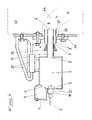
- FIGs 2 to 6 represent devices according to the invention mechanically activated, by mixed burners with liquids and gases ( figure 2 ), a four-stroke combustion engine ( figure 3 ), a two-stroke combustion engine ( figure 4 ), a turbine in an industrial version ( figure 5 ) and a pulsed reactor ( figure 6 ).
- FIG. 2 appended drawings illustrates a device according to the invention which is shaped for the use of liquids and gases regardless of their viscosity and regardless of the size, domestic or industrial, of said device.
- this variant of the general device of the figure 1 is shaped to selectively or simultaneously use liquids and / or gases by specific means adapted to the gaseous and liquid states (fluid or viscous).
- the resonance chamber 1 in particular provided with the supply means 2, the elongated pipe 4 and the orifice 6, is provided, depending on the application, with collection means 24 and / or discharge 25, 25 ' and a vent 23.
- a sleeve 29 for facilitating the adjustment of the soliton chamber 8 is fixed on the elongated pipe 4 of the resonance chamber 1 so as to keep the inlet of the air inlets 9 at the nodal plane of the elongate pipe 4 regardless of the position of the first opening 8 'of said soliton chamber 8 with respect to the end 4' of the elongated pipe.
- Said sleeve 29 creates between itself and the outer face of the elongated pipe 4 a passage for the air entering through the air inlets 9.
- Acoustic chamber 5 is provided with an acoustic device 7 (nozzle or acoustic reed) and is sealingly connected via orifice 6 to resonance chamber 1.
- acoustic device 7 nozzle or acoustic reed
- the supply means 2 consist of one or more injectors and / or nebulizers 19, 20, of the material or materials M, which may optionally be previously treated in order to obtain a appropriate presentation to said injectors and / or nebulizers 19, 20.
- the one or more injectors and / or nebulizers 19, 20 may advantageously comprise means 22 for heating the material or materials M intended to feed the resonance chamber 1.
- the supply means 2 of material M of the resonance chamber 1 may be constituted either by one or more gas injection nozzle (s) or by one or more injector (s) of liquid (s) supplied ( s) by an injection pump 21 variable flow incidentally reheated or by a mixed coupling of these two sources of supply.
- the resonance chamber 1 and / or the acoustic chamber 5 and / or the soliton chamber 8 and / or the Elongated conduits 4 are further provided with one or more collection means 24 and / or discharge means 25, 25 'of overflows, residues and / or combustion condensates produced, said collection means 24 and / or discharge 25, 25 'can be provided with vents 23, thermal protection means and / or cooling and / or heating and / or containment.
- the collection means 24 are arranged under and in proximity to the orifice 6 of the acoustic chamber 5.
- the evacuation means 25, 25 'of the overflow or saturation of the resonance chamber 1 may consist of pipes and be connected to a collection means 24 or common tank sealed to the outside air and provided with a vent 23 which opens, for example, into the resonance chamber 1 or the acoustic chamber 5.
- the soliton chamber 8 located in the longitudinal axis L of the device according to the invention and engaged on the end 4 'of the elongate pipe 4, is fixed on a mobile support in the form of a sliding carriage 31 on the fixed support itself made in the form of one or more rails 32 which are integral with the resonance chamber 1.
- the sleeve 29 can be moved by sliding friction in a direction parallel to the longitudinal axis L, thus displacing the air inlets 9 relative to the elements 33 fixed on the elongated pipe 4. This allows the adjustment of the distance between the first opening 8 'of this soliton chamber 8 and the end 4' of the elongated pipe 4, the space between the sleeve 29 and the elongate pipe 4 serving as a communication channel with the outside, whose section can be controlled by means or elements 33 made, for example, in the form of a conical sleeve adjustable by sliding or by helical rotation on said elongated pipe 4.
- a flow accelerator 30 also hereinafter referred to as "Venturi" with variable flow of the pulsating suction element 10, attached to the first opening 8 'of the soliton chamber 8 in a sealed manner, can also be fixed on the support common or trolley 31.
- this "Venturi” may be powered by a fan or a blower turbine 37 and its diverging may be equipped with ignition assistance means 12, for example, candle or electrodes.
- the one or more rails 32 serving as support means connected to the resonance chamber 1 may advantageously comprise a control device (not shown) for the first opening 8 '/ end 4' between the soliton chamber 8 and the elongated pipe 4. .
- the device represented in figure 2 operates in the following manner: the flow accelerator 30 or "Venturi” is started by operating the air source from the blower turbine 37.
- the fuel material (s) M (s) possibly heated (s) by the heating means 22 are injected into the resonance chamber 1 by the injector and / or nebulization devices 19, 20.
- the gases are injected by conventional low-pressure nozzles while the injection pressures of the liquids (proportional to their density) remain below the values usually used because of the contraction useful for their conditioning.
- the supply of the resonance chamber 1 is mixed, for example consisting of a mixture of gas and fuel oil, it is easier to start the reaction first with the gas, without this being an obligation.
- the use of heavy fuel oil or used oils is greatly facilitated if the gas or gasoline are used first or jointly with the medium or high viscosity materials. Subsequently, the starting aid fuel can be stopped.
- the gases and liquids sprayed or atomized by the injection pressure are conditioned by the vibratory circulation conditions of the resonance chamber 1 and arrive in the form of fog in the elongated pipe 4, sucked by the controlled effect of the soliton chamber 8.
- a device according to the invention intended for home use can be preset and calibrated once and for all and it can be limited to the settings of flow and adaptation to the environment.
- the soliton chamber 8 is tightly secured to the elongate pipe 4 and the external air inlet 9 is made in the form of a pipe penetrating inside the chamber.
- elongated pipe 4 taking its origin in the nodal plane of pipe 4 or still at one of the nodal planes of the device, for distributing the air at the end 4 'of this elongated pipe 4.
- the increase in power is more gradual and it is essential to follow the increase in load to avoid fumes of ignition.
- the adjustments can be automated, for example by monitoring, by means of sensors, the parameters identified at the strategic points of the device and through processing with computer programs.
- the relatively fluid gases and liquids are easy to implement because they are already in simple molecular form such as gases or in the form of fine droplets for the liquids sprayed by the injectors. They are vibration-sensitive and easily condense, a greater degree of freedom allowing rapid conditioning in small resonance chambers 1, in which the stationary flux rates are high, resulting in the occurrence of higher frequency pulses.
- the high kinetic rates of expansion create the accelerating vacuum at the nodal plane of the first opening 8 '.
- the first injections of the heating oil can advantageously be reheated for initial ignition.
- the enhancement of the vacuum amplitude created by nodal ionization of the first aperture 8 ' is sufficient to sustain the reaction.
- the means for regulating the forces applied by the pulsating suction element 10 combined with the devices making it possible to adjust the distance between the first opening 8 'and the end 4 are likely to cause ionizing acceleration without the need for electronic initial ignition.
- Heavy or used oils thus assume a dimension of the resonance chamber 1 which is adapted to their degree of freedom and to be continuously heated to a minimum temperature of about 70 ° C, so as to have the required viscosity for a sufficiently fine spraying without reaching the stage of the aerosol which would condense small particles and would then require an increase in the number of contractions and condensations to obtain aggregates carrying a significant charge potential.
- the flame resulting from the implementation of the device according to the invention is equivalent to a laser beam which pulses at low frequency. It has the coherence and the continuity property associated with the macroscopic soliton wave system, including in large industrial devices.
- the wavelength of the ionized field is a function of the value of the nodal speed pulse of the first opening 8 'relative to the load-bearing mass of the aggregates.
- it is possible to increase the power of the Venturi effect by referring to the SO 2 , O 2 and CO 2 contents of the gases emitted by making the necessary corrections (by acting on the arrivals 9 and the carriage 31 of the soliton chamber 8) and controlling the recirculation.
- evacuation means 25, 25 ' which do not change the atmosphere of these chambers are connected to less a collection means 24 sealed to the outside air and preferably provided with a vent 23 which returns to the resonance chamber 1 or the acoustic chamber 5.
- the advantages of this embodiment lie in the flexibility of the mixed or successive use of different fuels such as gas and fuel oil in domestic heating devices and that in the ease of implementation of heavy or used oils that are difficult to eliminate without risk.
- the amount of heat transmitted by the ionized field is greater than that of a conventional flame because of the stationary evolution generating a succession of expansion bellies increasing the heat exchange surfaces.
- the coherence of the large flame allows the implementation of large capacity furnaces limiting loss through the use of a single source of heat of great length.
- FIG. 3 illustrates a second embodiment of the device according to the invention.
- the device is actuated by a four-stroke internal combustion engine 41 powered by valves, the reaction produced in return by the device according to the invention maintaining the forced movement of the single or multi-cylinder engine 41.
- the soliton chamber 8 of the device according to the invention is constituted by the combustion chamber of the engine in the intake phase.
- the pulsating suction element 10 or cyclic is thus constituted by an explosion engine 41 comprising conventionally one or more intake valves 43 and exhaust either spark ignition or without ignition but with a larger volumetric ratio .
- the injection pump 21 for the injector and / or nebulization devices 19, 20 of the supply means 2 of the device according to the invention may advantageously be the multipoint injection pump of the multi-cylinder combustion engine 41.
- a flange 46 is placed at the inlet (outer) of the intake pipe 44 'to receive the sleeve 29 and facilitate its adjustment.
- the air inlet (s) 9 of the soliton chamber 8 are located in line with the nodal plane of the elongated pipe 4, the total length of which corresponds, by way of non-limiting example, to the length of the stroke of the piston 45. for +/- 110 ° of rotation from TDC (top dead center) to PMB (bottom dead center).
- the air inlet (s) 9 of the soliton chamber 8 may also be located in line with one of the other possible nodal planes of the device.
- the resonance chamber 1 is also provided with an acoustic chamber 5 provided with an orifice 6 and with an acoustic device 7 made, for example, in the form of an acoustic nozzle or an acoustic reed.
- the supply means 2 of the resonance chamber 1 are arranged facing an outlet 3 of said resonance chamber 1 and on the longitudinal axis of an elongated pipe 4 .
- the supply means 2 of the resonance chamber 1 are always placed on the opposite side to the one receiving the elongated pipe 4 but in such a way that the injector and / or nebulizer devices 19, 20 are, ideally but not limitatively, in the longitudinal axis of the resonance chamber 1 because of its small volume.
- the acoustic chamber 5, its acoustic device 7 and its orifice 6 are therefore in a laterally offset position with respect to the resonance chamber 1, unlike the arrangement represented for example on the figure 2 , where all the aforementioned elements are centered on the horizontal axis L.
- the starting of the combustion engine 41 is done by a conventional means of launcher or starter.
- the injection of the materials M is set so that it introduces the selected fuel into the resonance chamber 1 exactly at the instant of the opening of the intake valve 43.
- the closing of the intake valve 43 does not must not intervene before 290 ° of the crankshaft turn since the TDC of beginning of admission.
- the volume of the combustion chamber of the internal combustion engine 41 constitutes a soliton chamber 8, the intake pipe 44 'of which corresponds to the narrow ovoid side (first opening 8') of the combustion chamber. solitons 8 more general described in the previous embodiments.
- the piston 45 against which a "belly" of movement is formed generates at least one nodal plane at each vertical movement.
- the incident wave of depression produced by the movement of the piston 45 at the inlet passes through the soliton chamber 8, which cooperates with the intake pipe 44 'before continuing its way to the bottom of the resonance chamber 1 where it is reflected towards the soliton chamber 8 after undergoing a series of reflections in the resonance chamber 1.
- the depression gives rise to a first compensation by the passage of the outside air through the air inlets 9 constitutive solitons but with a shift due to the advanced position of the 4 'end of the elongated pipe 4 relative to that of the air inlets 9.
- the stroke of the piston 45 generates in this way several depression pulses which are reflected on the bottom of the resonance chamber 1, activate the acoustic device 7 and each time involve an external air wave component of the soliton propagation, whose amplitude increases with each pulse received from the piston 45.
- the resonance chamber 1 and the variable-volume combustion chamber of the combustion engine 41 are in state of depression, it is the amplitudes of contractions which are reinforced.
- the PMH after closing the inlet valve 43 constitutes the virtual nodal plane equivalent to that of the first opening 8 'of the soliton chamber 8 of the previous embodiments. It is at this moment that the "complement" of vacuum must intervene by the ignition by means of ignition assistance 12, here a candle. Faster than in conventional systems, this operation requires less advance and must be programmed to +/- 10 ° ahead of the TDC.
- ignition assistance 12 here a candle.
- the position of the end 4 'of the elongate pipe 4 in combination with the adjustment of the air inlets 9 and the position of the carriage 31, factors of the macroscopic wavelength of the field soliton, which make it possible to position the nodal plane preceding the acceleration just at the level of the PMH.
- the contraction of the field after PMB consumption consumes the heat of the combustion chamber, which results in the engine heating less than its conventional counterpart.
- the stationary movement continues after ionization, the emptying of the soliton chamber 8 is facilitated by the contraction of the exhaust field.
- the ionization does not give rise to oxidation reactions, the engine operating with the device according to the invention is "clean" and particularly interesting for the environment.
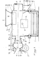
- FIG. 4 appended drawings illustrates a third embodiment of the device according to the invention.
- the device is actuated by a two-cycle dotted-line engine 42 (in dashed lines), in which the soliton chamber 8 is distributed between the two pulsating volumes: the inlet connected to the outlet 3 of the resonance chamber 1 and the combustion chamber, as described below.
- this embodiment of the device according to the invention comprises a number of means common to those described in previous embodiments which will not be all recited or redescribed here.
- the device is introduced into the inlet opening, either of the low motor, or by the inlet pipe 44 in the case of a secondary chamber.
- a flange 46 is also placed on the inlet of the inlet for receiving the sleeve 29 and facilitate its adjustment.
- the fuel is introduced by one or more injector and / or nebulizer devices 19, 20 and, depending on its nature, into the resonance chamber 1, at the precise moment of the beginning of the admission.
- the fuel is conditioned and introduced into the space formed by the combination of the conditioning space with the combustion chamber.
- the exit light in the combustion chamber remains open more long time.
- a valve or valve located on the transfer channel closes after 290 ° or by pressure effect so as to oppose the return to the resonance chamber portion 1 (conditioning chamber).
- the device according to the invention can be mounted on a conventional engine and does not require other modifications.
- soliton chamber part 8 If the conditioning is performed in a soliton chamber part 8 annex its volume must beat exactly opposite to that of its complement, the combustion chamber. Indeed, the contribution of the two volumes varying in the opposite direction reproduces ideally the stationary conditions of the soliton chamber 8 of the device of the figure 1 or 2 wherein there is a speed "belly" at the end 4 'of the elongated pipe 4 and a contraction nodal plane of the first opening 8'.
- the moment of injection is dictated by the low position of the piston at the start of the intake by its ascent towards the TDC.
- the fuel introduced by several injector and / or nebulization devices 19, 20 is packaged in the resonance chamber 1 and then sucked through the elongated pipe 4 by raising the piston towards the PMH.
- the field arrives in the "speed belly” condition by the end of the elongated pipe 4 in the part of the soliton chamber 8.
- This contraction is a function of the adjustments, by the position of the carriage 31, of the end 4 'of the elongated pipe 4 and the adjustment of the air inlets 9.
- the wavelength must also be adjusted with respect to the TDC so that the ionization is not early, which would bump the engine, or late, which would lose power.
- the speed or internal frequency of the field can be controlled by the acoustic nozzle of the acoustic chamber 5 without variation of the fuel flow or by increasing the quantity of particles by increasing the flow rate of the injector and / or nebulizer devices 19, 20.
- the expansion following the TDC acceleration pushes the piston towards the PMB and, according to the stationary process, towards the PMB where the expansion becomes contraction creating a vacuum at the time of the escape at the same time as the material field which follows, conditioned in the first part is in dilatation all open intake and exhaust transfer lights.
- the contraction of the exhaust promotes the introduction of the field prepared by its intake transfer light without the need for a check valve in the part of the air inlets 9 of the chamber fraction to solitons 8 at the entrance to the elongated pipe 4.
- the high light of the feed transfer is open upwards so that its closure by the piston is delayed, in order to increase the transfer delay.
- a check valve or a controlled valve is then interposed in the transfer channel, so that the material field is not disturbed in the preparation zone by a pressure return of the driving phase (after ionization), which would lead to in addition to a loss of power.
- FIG. 5 of the accompanying drawings illustrates a fourth embodiment of the device according to the invention.
- the device is actuated by a gas turbine 38 contiguous to the first opening 8 'of the soliton chamber 8 or the flow accelerator 30 or "Venturi", the first blade 39 producing a pulsating suction.
- the device according to this variant is of a nature to use at least two phases of expansion whereas the piston systems previously described use only one.
- a gas turbine 38 has at the inlet, before a first combustion chamber 48, a first blade 39 of a suction turbine 47 which is connected directly to the flow accelerator 30 or "Venturi" adjustable, open on the outside which follows the first opening 8 'of the soliton chamber 8 of a device such as in particular described in the embodiments illustrated in FIGS. figures 1 or 2 .
- the gas turbine 38 is equipped with a launcher or starter to create the starting suction. Following the suction turbine 47, there is a combustion chamber 48 consisting of a divergent section followed by a portion of cross section which ends with a turbine 49.
- the combustion chamber 48 is equipped with a means
- the output of the receiver turbine 49 opens on a divergent chamber section 40 connected to a longer convergent section terminated by another turbine 50, the two associated sections constituting the chamber 51, provided with air inlets 9 of adjustable sections communicating with the outside and located in the divergent section 40.
- the output of the turbine 50 opens on a divergent section open on the outside. All the turbines are integral with a shaft 52 that can be connected to a conventional energy generating means 53.
- the suction turbine 47 is actuated by the starter. At the same time fuel is continuously injected into the resonance chamber 1 by suitable devices (not shown). The suction caused by the suction turbine 47 conditions the fuel field in the resonant resonant chamber 1 under the effect of the acoustic device 7 of the acoustic chamber 5 (not shown). Field conditioned is sucked by the elongated pipe 4 and is present at the nodal passage of the first opening 8 'where it undergoes an acceleration. Absorbed by the suction turbine 47, it opens into the combustion chamber 48 where the electronic ignition assistance means 12 completes the acceleration and initiates the flame.
- a diverging chamber section facilitates the escape of the passages through this turbine by creating a contraction zone controlled by the air inlets 9 of adjustable sections in contact with the outside to avoid the condensation and the abortion of the stationary system constituting a new dilation which follows the contraction.
- the expansion generating a new pressure is contained by a convergent section which guides the field on a new turbine 50.
- the passages of this turbine oriented in the same direction as those of the turbine 49, also receive a pressure in one direction. rotation transmitted to the shaft 52, which this turbine 50 is secured.
- the output of the turbine 50 opens on a divergent duct section and open on the outside which promotes the passage through the blades.
- FIG. 6 of the accompanying drawings illustrates a fifth embodiment of the device according to the invention.
- This device uses the devices of the figures 1 or 2 to dilate the air admitted to positive pressure in a combustion chamber and multiply this pressure by the heat and the amount of movement transmitted to this air by the ionized field from a divergent exhaust that makes it a propulsion device by reaction in the ambient air.
- the present propulsion device consists of one of the devices figures 1 or 2 , whose soliton chamber 8 is associated with one or more convergent deflectors 35.
- This or these deflectors 35 are integral with a chamber of an expansion 36 'of spherical or cylindrical shape, the coupling of which to the soliton chamber 8 forms a flow accelerator 30 or "Venturi" supplied by the deflector (s) 35 followed by a section of divergent section, the continuation of the expansion chamber 36 'terminating in a convergent section connected to a divergent outlet 36''.
- the expansion chamber 36' and the associated deflector (s) 35 are integral with a carriage 31, the position of which can be regulated by relative to the general support made in the form of one or more rails 32.
- the divergent outlet air pressure distortion 36 "being propellant, the direction of operation is determined by a direction of movement characterized in that the acoustic chamber 5 is located at the front of the device and in which the diverging portion 36 "constitutes the rear part.
- a blower turbine 37 supplies the convergent deflector 35 during the activation phase.
- the device described above is started according to the direction of operation of the acoustic chamber 5 and its acoustic device 7 located at the front.
- the deflector (s) 35 capture a quantity of air which is pressurized by the reduction of the convergent direction of these deflectors 35.
- the air pressure at the bottom of the convergent (s) is applied and actuates the "Venturi".
- the resulting pulsating suction acts on the soliton chamber 8, is transmitted to the resonance chamber 1 by the elongated pipe 4 and thereafter by the acoustic chamber 5 to the acoustic device 7 which reacts by printing a vibration at pulsating system.
- the fuel injection is activated in the resonance chamber 1, whose macroscopic pulsation regime doubled the vibratory effect transmitted by the acoustic chamber 5 conditions the injected fuel in the form of field or fog.
- the field of particles or fog is sucked by the elongated pipe 4 and is at the nodal plane of the first opening 8 'to undergo the acceleration completed by the ignition of the ignition assistance means 12 which ionizes the field.
- the distance 4 '/ first opening 8' and first opening 8 '/ expansion chamber 36' and air inlet 9 parameters are adjusted according to the objective.
- the opening of the "Venturi" is increased by adjusting the position of the carriage 31 'secured to the expansion chamber 36'.
- the divergent 36 "then contributes to the supersonic ejection of the mass of the moving field which abuts on the outside atmosphere.
- said divergent 36 advantageously has an elongated and progressive shape which tends to move towards the back the void space of the nodal plane and distributing the resulting thrust on a section and not at a point, which would have destructive effects.
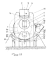
- FIGS 7 to 11 represent devices according to the invention in which the resonance chamber 1 has been adapted to the nature of the materials M used.
- variants that are particularly suitable for treating tires and waste provide for the use of a fixed bowl ( figures 7 and 8 ) or mobile ( figures 9 and 10 ), residue extraction means, precipitated tanks, etc.
- the variant represented in figures 7 and 8 provides a resonance chamber 1 provided with a hopper 14 particularly intended for solid and / or melting materials (wood, plastics ).
- the device for the treatment of heterogeneous waste solid consists of a fixed resonant chamber 1 having a volume adapted to the nature of the waste.
- This resonance chamber 1 is characterized by an eccentric alignment of the axis connecting the soliton chamber 8 to the acoustic device 7, a bulge at the bottom of the resonance chamber 1 which is equipped with a double partial protective enclosure or a heat exchange device in the solids deposition zone and at least one stirring device 18.
- the device according to the invention is characterized by its simplicity of implementation. According to figure 7 it comprises a resonance chamber 1 provided on one side with an elongated pipe 4 and on the other side, an orifice 6 opening into an acoustic chamber 5 provided with an acoustic device 7.
- the resonance chamber 1 is arranged to receive the material in its lower part on a coating 1 'insulating, refractory or simply a double wall of the outer casing.
- a sleeve 29 for facilitating the adjustment of the soliton chamber 8 is fixed on the elongated pipe 4 of the resonance chamber 1 to form one or more air inlets between said sleeve 29 and the outer face of said elongated pipe 4.
- an additional sleeve (not shown) can be placed inside the elongated pipe 4 if the latter is of large size.
- the at least one feed opening 13 is surmounted by at least one hopper 14 which can be provided with an upper closure door 15 and a lower closure door 16 and / or with a lower grid 17.
- the hopper or hoppers 14 may comprise heating means 22 (not shown) of the material or materials M intended to feed the resonance chamber 1.
- the device may also include one or more outlets 54 made, for example, in the form of a hatch 55 and a sealed ashtray 56 closed by a discharge 57 and / or in the form of a sliding door 58 which opens onto a container cooling member 62 integral with and communicating with the resonance chamber 1 through a vent 59 in said sliding door 58, said cooling container 62 being able to be provided with an unloading door 60 sealed from the outside and provided with a telescopic gripping means 61 for discharging said waste.
- outlets 54 made, for example, in the form of a hatch 55 and a sealed ashtray 56 closed by a discharge 57 and / or in the form of a sliding door 58 which opens onto a container cooling member 62 integral with and communicating with the resonance chamber 1 through a vent 59 in said sliding door 58, said cooling container 62 being able to be provided with an unloading door 60 sealed from the outside and provided with a telescopic gripping means 61 for discharging said waste.
- the device comprises, as explained in the previous embodiments, a soliton chamber 8 located in the axis and in front of the elongated pipe 4, fixed to a carriage 31 movable on one or more rails 32 integral with the resonance chamber 1.
- the size of the inflow inlets 9 varies with the sliding friction of the carriage 31 on the or rails 32, the sleeve 29 attached to the elongated pipe 4 sinking more or less deeply on said elongated pipe 4 by adjusting the distance between the first opening 8 'of the soliton chamber 8 and the end 4' of the elongated pipe 4, the space between the sleeve 29 and the pipe elongated 4 thus acting as a passage communicating with the outside, whose opening can also be controlled by the elements 33 made, for example, in the form of another conical sleeve which can be moved by sliding or by helical rotation on elongated pipe 4.
- the pulsating suction member 10 and the flow accelerator 30 (Venturi" or other variable flow), contiguous to the first opening 8 'of the soliton chamber 8 in a sealed manner, are fixed to the common support namely , the carriage 31 moving on the rails 32.
- the pulsating suction member 10 is powered by a fan or a blower turbine 37 or its movement is maintained by the reaction once activated or by a static draft of the type of that of a chimney.
- the diverging portion of the pulsating suction member 10 is equipped with ignition assistance means 12 by spark plug or electrodes.
- the device according to the present invention is also characterized in that at least one device 18 is provided for mixing the solid material (s) M introduced into said resonance chamber 1.
- Such a device 18 for mixing the material may be, for example, an oscillating stirring means with arms, with longitudinal vanes, etc., the partial axes of which 18 'may be located centrally in the axis of the resonance chamber. 1 (cf. figure 8 ) and which communicate with the outside to be driven by a motorized device (not shown) generating the oscillating movement of the stirring device 18 by means of pinions, connecting rods, hydraulic means or any other suitable means.
- Manual or automatic control means may also be fitted to all the aforementioned movable members and a computer control and management center connected to strategically located sensors may also be provided to control the movements of the above-mentioned adjustment members.
- the material or materials M supplied by successive charges are placed in the hopper 14 fixed.
- the upper door 15 is then closed, the opening of the lower double door 16 allowing the materials M to pass into the resonance chamber 1.
- the lower door 16 closed, the hopper 14 can be refilled for a new supply cycle of the resonance chamber 1.
- the resonance chamber 1 When the resonance chamber 1 is loaded with a sufficient quantity of materials M, ignition is carried out in a conventional manner. In particular, it is possible to add easily flammable materials to the first load (paper, cardboard ...) to facilitate this ignition.
- the ignition being effected, the blower turbine 37 and, consequently, the flow accelerator 30 are put into action as well as the ignition assistance means 12. To quickly activate the ignition, it is fully open. Adjustment of the acoustic device 7.
- the flow accelerator 30 is set to lowest in correlation with the widely open air inlets 9 of the soliton chamber 8 and with the first opening 8 'close to the end 4' of the chamber. elongated driving 4.
- the stirring device 18 When the mass is well ignited, the stirring device 18 is operated, either at slow speed and continuously, or more rapidly but intennittente. As soon as the actual ignition is achieved, it gradually closes the air passage of the acoustic device 7 so as to gradually raise the depression at the same time as the pulsating regime is established. Shortly after the appearance of the fog at the flow accelerator 30, the flame is established in the divergent "Venturi". When the flame is stabilized, the ignition assistance means 12 can be stopped.
- the progression of the radiating flame is monitored by appropriate maneuvers, such as adjustment of the acoustic device 7 towards its minimum operating point, increase of the first opening distance 8 ' / output 3 (or the first opening distance 8 '/ end 4'), adjusting the inlet of the air inlets 9 and ramping up of the flow accelerator 30 to establish the flow rate corresponding to the conditioning speed in the resonance chamber 1.
- the flow rate at the "Venturi” is too slow compared to the conditioning speed in the resonance chamber 1, the particle field is saturated and heavier, the speed pulse at the passage of the first opening 8 'insufficient showing C x H y unburned.
- the depression force applied by the flow accelerator 30 is too high or the entry of the air inlets 9 is too restricted, the reinforcement of the contraction amplitudes due to the liberations of the hydrogen is poorly compensated and piezoelectricity is observed by the appearance of SO 2 and nitrogen oxides NO x .
- the wrong setting also results in fouling of the elongated pipe 4 and / or tar production in the soliton chamber 8.
- the defect may be the sole fact of an oxygen deficiency measured in the discharges. In this case, it is due to the opening of the air inlets 9 and the force applied by the "Venturi" which must remain strong enough to promote the wave reflection in the form of recirculation.
- the hopper 14 has been reloaded and, as the load of the resonance chamber 1 decreases, the lower doors 16 are opened to introduce a new charge into the resonance chamber 1.
- the lower doors 16 close again and a new cycle can begin according to the transformation speed prevailing in said resonance chamber 1.
- Heterogeneous waste such as household waste, as well as tires may include metal parts such as reinforcements and others that emerge from the more consistent mass of material like large gravels emerging from a pile of sand and falling down. on the edges of said pile which in this case corresponds to the center of the amplitudes of the mixing of the mass at depth by the blades. It is the same for ashes.
- the amount of unburned accumulated material exceeds a certain limit, it must be removed. This operation can be programmed or carried out at any time, the evacuation container being secured to the resonant chamber 1. For this, the sliding door 58 is opened, the gripping means 61 (grapple, claw or telescopic articulated gripper).
- the opening or the hatch 55 of the ashtray 56 may be preferentially under the orifice 6 because of the effect of precipitation induced at this level by the fresh air stream coming from the acoustic device 7.
- the wall of the resonance chamber 1 may be lined with a coating insulating it, for example a blade of water connected to any cold source.
- the figures 9 and 10 represent another embodiment of the device according to the invention, characterized by the setting in motion of the resonance chamber 1 to obtain a mixing of the materials in large chambers adapted to the treatment and the conditions handling heterogeneous solid waste containing, for example hydrocarbons.
- the device represented in said figures is characterized in that the resonance chamber 1 contains solids, deposited at the bottom of the latter. These materials being static, they are then brewed or stirred to ensure the maintenance and regularity of the transformation reaction.
- the device shown comprises a resonance chamber 1 provided with an elongated pipe 4 and an acoustic chamber 5 provided with an orifice 6 and is arranged to receive the material in its lower part on a coating insulating, refractory or simply a double wall of the outer casing, the alignment axis of the elongate pipe 4 and the orifice 6 being eccentric towards the top of the resonance chamber 1 which has on its lower outer face one or more strips 63 of bearing and rollers 64 of bearings positioned according to the axis of rotation defined by the elongate axis 4-port 6 relative to the axis of the resonance chamber 1.
- the elongated pipe 4 consists of an open pipe at both ends, one sealingly connected to one side of the resonance chamber 1 and the other constituting the 4 'end entering the soliton chamber 8 (1). Pulsating suction member 10 and its accessories is only suggested in this view) opposite its first opening 8 '.
- At least one recirculation guide 26 of section smaller than that of the pipe or lines 4 is provided at least partly within said elongate conduit (s) 4, for example in the form of an elongate sleeve opening into the resonance chamber 1.
- this recirculation guide 26 defines the recirculation space of the compensation air of the depression of the resonance chamber 1.
- a sleeve 29 intended to facilitate the adjustment of the operation of the soliton chamber 8 is fixed on the elongated pipe 4 of the resonance chamber 1 to form a passage for the air inlets 9 between itself and the outer face of said elongated pipe 4.
- An external reinforcement to the elongated pipe 4 flush with the resonance chamber 1 constitutes an axis of movement inside a bearing 65.
- the feed opening 13 of material M of the resonance chamber 1 is closed by a sliding panel 15 "with controlled or automatic opening
- the feed means 2 is advantageously constituted by a hopper 14 closed by a door upper loading 15 and a lower door 16 unloading two leaves and is made integral with a positioning device itself integral with the frame 66, all movements can be controlled manually or automatically.
- the device illustrated in figures 9 and 10 can also include one or more outputs 54 made, for example, in the form of an ashtray 56 closed by a hatch 55 facing the outside for a possible emptying.
- a second outlet 54 by a sliding door 58 gives a airlock 56 'vis-à-vis the outside and provided with a second sliding door 58' facing the sliding door 58, so to be at the same time. horizontal during the low discharge position (cf. figure 10 ).
- a gripping means 61 telescopic team the airlock 56 '.
- a sealed cooling container 62 is connected by a flexible hose to the airlock 56 ', the sliding door 58 of which has a special vent 59 permanently open on the resonance chamber 1.
- the acoustic chamber 5 is provided with its acoustic device 7, the orifice 6 is shaped, in a non-limiting form of use, to form an axis of movement inside a bearing 65.
- the soliton chamber 8 located in front of the elongated pipe 4 and in its axis, is fixed to a carriage 31 which is carried by one or more rails 32 which are integral with the frame 66 so that said soliton chamber 8 can slide on the sleeve 29 integral with the elongated pipe 4 of the resonance chamber 1 for adjusting the distance between the first opening 8 'of the soliton chamber 8 and the end 4' of the elongated pipe 4, the space between the sleeve 29 and the elongated pipe 4 serving as an air passage for the air inlets 9, the section of which can be controlled by elements 33, for example, another conical sleeve that can be adjusted by sliding or else by helical rotation on the allon pipe 4.
- the pulsating suction member 10, the variable flow rate accelerator 30 ("Venturi", adapted turbine, motor, etc.) is attached to the first opening 8 'of the soliton chamber 8 in a leaktight manner. pulsating suction member 10 being fixed, with said soliton chamber 8, to the common support (carriage 31). It is powered by a blower turbine 37 and optionally equipped with ignition assistance means 12, by candle or electrodes as required.
- the one or more rails 32 integral with the frame 66 comprise a device for adjusting the stroke between the first opening 8 'and the outlet 3 (or the end 4' of the elongated pipe 4 which defines the reference point of the half-wave flow which guides the position of the first opening 8 'of the soliton chamber 8).
- the device also comprises running strips 63 and rolling rollers 64 for the support cradle of the resonance chamber 1, integral with a fixed frame 66 which comprises the bearings 65 and the support base of the mobile soliton chamber 8 .
- a device generating the oscillating movement of the resonance chamber 1 is also provided, as well as means for controlling the mobile members, a center of control and computer management connected to sensors located at strategic locations and setting devices.
- the resonance chamber 1 has its sliding panel 15 "opposite the lower door 16 of the hopper 14 and triggers a lashing lock which blocks the movement of the resonance chamber 1.
- the sliding panel 15 "opens to allow the opening of the lower double door 16 of the hopper 14.
- the material or materials M fall into the chamber of Resonance 1.
- the doors close in the reverse order.
- the resonance chamber 1 When the resonance chamber 1 is loaded with a sufficient quantity of materials M, it is started and started as previously explained.
- the sliding panel 15 " In the case of a triggering of the blocking set on, for example six oscillations (estimated time for the disappearance of a quantity of treated material in the resonance chamber 1), the sliding panel 15 "is in front of the hopper 14 the latch secures the resonance chamber 1 and stops the driving force of the oscillating movement.
- the hopper 14 moves down, the sliding panel 15 "and the lower door 16 open successively, the load slides the resonance chamber 1, the doors close in the opposite direction, the unlocking releases the moving assembly, the oscillation driving source is reactivated and so on depending on the programming depending on the consumption of materials M in said resonance chamber 1.
- Heterogeneous waste such as household waste, as well as tires may include metal parts such as reinforcements and the like that emerge from the more consistent mass of material such as coarse gravel emerging from a pile of sand and falling down. on the edges of said pile which in this case corresponds to the center of the amplitudes of the mixing of the mass at depth by the blades. It is the same for ashes.
- the amount of unburned accumulated material exceeds a certain limit, it must be removed. This operation can be programmed or performed at any time, the airlock 56 'evacuation being secured to the resonance chamber 1.
- the gripping means 61 (grapple, claw or telescopic articulated gripper) rakes the deposited materials and returns the ashes to the ashtray 56 provided for this purpose. Then he grabs, shakes or vibrates the recovered materials to remove adhesions and comes to deposit them in a cooling container 62 pending their final evacuation.
- the opening or the hatch 55 of the ashtray 56 may be preferentially under the orifice 6 because of the effect of precipitation induced at this level by the fresh air stream coming from the acoustic device 7.
- the airlock 56 ' is located vertically of the cooling container 62.
- the cooling container 62 is raised for example by hydraulic means to stick against said airlock waterproof 56 '.
- the second sliding door 58 'and the unloading door 60 facing each other open and the waste airlock 56' fall into the cooling container 62.
- the doors close and the two joint operations are performed without interrupting the operation of the reaction, the movement of the assembly can resume and continue in this manner repeatedly.
- the ashtray 56 being independent, it is possible to empty it in an auxiliary container provided for this purpose during a loading stop. It is the same for the maintenance of the acoustic chamber 5.
- the wall of the resonance chamber 1 may be lined with a coating insulating it, for example, a water blade connected to any cold source.
- the hopper (s) 14 can be moved above the feed openings (13) of the resonance chamber (1), from a feed opening (13) to another feed opening (13).
- the devices described in figures 1 , 2 , 7 and 8 are suitable for use with a variety of M materials, including those generally referred to as plastics which for the most part melt under the effect of heat prior to combustion. This property is an obstacle to the implementation of plastics in the aforementioned devices insofar as the charge of the resonance chamber 1 whole bottom and in this case produces a saturated field of matter which exceeds the capacity of the machine.
- the flow rate is a function of the size of the chamber. resonance 1 and will be easy to adjust as needed even by an external heat source.
- the grid 17 is also interesting when using wood as material M, the device according to the invention, equipped with adequate waste outlets, also constituting a burner device for gases from the wood processing.
- the figure 1 shows a device according to the invention shaped for the implementation of solid materials M (wood, plastics ...) in domestic or industrial devices characterized in that one or more walls of the resonance chamber 1 is or are composed of one or more grids 17 and in that said resonance chamber 1 is provided with additional devices (or their variants) for extracting overflow or waste, for example such as those shown in the drawings. figures 1 and 2 .
- the illustrated device comprises supply means 2 of the resonance chamber 1 constituted by a hopper 14 of large size provided with an upper door 15 and having a grid 17 that can be movable and adjustable instead of a lower door 16
- the resonance chamber 1 further comprises means 24 for collecting and discharging 25, 25 'of the ashes.
- These means can be ashtrays as well as means for evacuation of overflow by pipes whose orifices are located at suitable levels and which are connected to a central tank with a vent 23.
- the device according to this variant operates as follows: the material or materials M are placed in the hopper 14 which is ignited under the grid 17 in the resonance chamber 1. If it is plastics these are previously melted by a heating device applied to the bottom of the hopper 14 so that these materials M flow into the resonance chamber 1 where they are ignited in a conventional manner. When the conventional combustion is initiated, the pulsating suction member 10 is actuated.
- the resulting pulsating suction acts on the soliton chamber 8, is transmitted to the resonance chamber 1 by the elongated pipe 4 and, by the acoustic chamber 5, to the acoustic device 7 which reacts by printing a vibration to the system pulsing.
- the macroscopic pulsating regime coupled with the vibratory effect transmitted by the acoustic chamber conditions the species or aggregates resulting from the first dissociation in the form of a field or fog.
- the field of particles or fog is sucked by the elongate pipe 4, is at the nodal plane at the first opening 8 'to undergo the acceleration completed by the ignition assistance means 12 which ionizes the field.
- the distance 4 '/ first aperture 8', air inlet 9 and flow rate parameters are adjusted according to the objective to be attained by the pulsating suction member 10. If wood is used, the capacity the hopper 14 provides a large autonomy, a vent 23 whose origin is at the resonance chamber 1 ensuring the regulation of the pressure when the upper door 15 of said hopper 14 is closed.
- the collecting means 24 may be an ashtray positioned accordingly in which the ashes are evacuated as needed.
- the conduct of the heating is governed by the controls of the distance between the first opening 8 'and the end 4', the air inlets 9, the flow at the first opening 8 ', whether manually or automatically . If the materials M are plastics, the hopper 14 of large size avoids the return of gas or smoke by the pad of materials.
- the ashtray is preferably placed under the orifice 6 to receive the precipitation of the mineral fillers, the discharge means 25, 25 'ensuring the regularity of operation.
- the figure 12 represents a device according to the invention which is activated by static means for the production of heat from solids.
- the device illustrated on the figure 12 is shaped to be activated by a pulsating suction member 10 operating statically and is vertically shaped to be subjected to the action of a vertical flow channel.
- a soliton chamber 8 connected to a vertical discharge channel by its first opening 8 ' is located above the resonance chamber 1 to which it is connected by its elongated pipe 4 and is in communication with the outside by one or more air inlets 9 of sections at least equal to those of the pulsating suction member 10, that is to say the static flue gas duct 34, so as to compensate for its effect.
- a protective lining or coating 1 'receives and contains the weight materials on a grid 17' placed above the acoustic chamber 5 equipped with an acoustic device (nozzle) 7, the orifices 6 through the grid 17 'making Office of pinching. Above the upper edge of this coating 1 'are located one or more elements 33 for regulating the flow rates of the air inlets 9.
- the device is supported by a frame 66 so that the air inlets 9 and the acoustic device 7 are freely powered by the external atmosphere.
- the wall of the resonance chamber 1 may be equipped with a water strip so as to distribute the heat, for example on radiators.
- the device illustrated in figure 12 operates as follows: the material or materials M are placed in the enclosure of the bottom doubling of the resonance chamber 1 from one of the feed openings 13, directly from outside or from the hopper 14.
- the discharge channel is open, connected by the ionization gap 11 to the first opening 8 'of the soliton chamber 8 itself connected to the outside by the air inlets 9 whose opening is reduced by the adjustment of the elements 33, while the bypass 34' is closed by its element 33 '.
- the acoustic nozzle of the acoustic chamber 5 is open to the maximum.
- the material charge M is lit if necessary with paper and small wood.
- the direct circulation generated by the full pulling power of the pulsating suction member 10 (constituted by the static pipe of fumes 34) which is not compensated due to the reduction by the adjustment of the air inlets 9 causes a very fast firing of the load of materials M.
- the nozzle is adjusted to its minimum passage position which resonates the acoustic chamber 5, the depression of which generates a recirculation of the dissociated species at the gate 17 'through the orifices 6.
- the adjustment of the elements 33 of the air inlets 9 is then fully opened.
- the flow of air supplied to the soliton chamber 8 is distributed between the first opening 8 'reducing the suction of the static pipe of fumes 34 and the elongated pipes 4 where the recirculation compensates for the strong depression generated by the initial action of said static smoke pipe 34 increased by the extreme reduction of the acoustic device 7.
- the internal mass of the materials M placed on the coating 1 'and the grid 17' glows and forms ember, the desired objective is achieved and the heat is produced at inside the resonance chamber 1 whose walls radiate outwards.
- the flames retain a classic appearance even if they are clear and bluish and that the oxidation is already very reduced compared to a conventional system. This is due to an excess of suction force of the pulsating suction member 10 which is only partially compensated at the first opening 8 'by a part of the flow delivered to the soliton chamber 8 by the arrivals of 9, the other part circulating in the opposite direction through the orifices 6 to tend to partially rebalance the pressure in the acoustic chamber 5.
- the use of the hopper 14 continuously promotes the quality of the treatment insofar as the solids M are preheated before their arrival on the grid 17 '.
- an adapted ashtray for example an ashtray 56
- evacuation means connected to a collection means and a vent for example the evacuation means 25, 25 'connected to the collecting means 24 and to the vent 23
- all the soliton chambers 8 are able to produce condensates recoverable by a flow at the bottom of said soliton chamber 8, for example by means of a pipe connected to a tank.
- liquid crystals are produced rather whereas the ashtray 56 produces more or less viscous oil with choice.
- the condensates produced by the soliton chamber 8 are generally loaded with aggregates and solid crystals of the fullerene type which are unsuitable for conventional explosion engines, due to the presence of pure carbon crystals in the form of microscopic diamonds which use the segments and shirts.
- the process according to the invention is also characterized in that it comprises, in addition, a step of optimizing the reaction after the ionization step of the one or more conditioned materials M by adjusting one or more of the parameters following: opening of the acoustic device 7, power of the pulsating suction member 10, flow of air entering through the air inlets 9, position of the air inlets 9 with respect to the nodal plane of the elongate pipe or pipes 4 or another nodal plane of the device, the distance separating the second opening 8 "from the outlet (s) 3 of the resonance chamber 1, adjusting the length of the elongated pipe (s) 4, in order to adapt the system the ionization reaction of the material or materials M at the speed of conditioning of said materials M in the resonance chamber 1.
- the concentrations of SO 2 , C x H y , NO x or O 2 , of the air rejected by the device according to the present invention are measured in order to determine the adjustment of the one or more the following parameters: power of the pulsating suction element 10, position of the air inlets 9 with respect to the nodal plane of the elongate pipe or pipes 4 or another nodal plane of the device, air flow entering through the air inlets 9, the distance separating the first opening 8 'from the outlet (s) 3 of the resonance chamber 1, adjusting the length of the pipe (s) 4, adjusting the acoustic device 7, in order to optimize the ionization reaction of the material (s) M to obtain an O 2 concentration in the effluent stream that is at least equivalent to the atmospheric concentration and concentrations of SO 2 , C x H y and / or NO x zero or virtually zero.
- the ignition assistance means 12 is turned off when the ionization reaction of the material or materials M continues independently.
- the energy released by the dissociated and conditioned material (s) M (s) before their ionization in the form of one or more noble materials is stored by condensation before the ionization of the material (s) created. in the collection means or 24 condensates.
- the process according to the present invention can be used for the production of thermal, chemical and / or mechanical energy. As explained above, it can also be used for the production of noble materials.
- the present invention also relates to an incinerator, in particular waste, a recological heat engine, in particular for vehicles, a turbine, a ramjet and household fireplaces and boilers using the device according to the invention.
Landscapes
- Engineering & Computer Science (AREA)
- Chemical & Material Sciences (AREA)
- Physics & Mathematics (AREA)
- Plasma & Fusion (AREA)
- Combustion & Propulsion (AREA)
- General Engineering & Computer Science (AREA)
- Chemical Kinetics & Catalysis (AREA)
- Mechanical Engineering (AREA)
- Acoustics & Sound (AREA)
- Spectroscopy & Molecular Physics (AREA)
- Organic Chemistry (AREA)
- Physical Or Chemical Processes And Apparatus (AREA)
- External Artificial Organs (AREA)
- Soundproofing, Sound Blocking, And Sound Damping (AREA)
- Treatments Of Macromolecular Shaped Articles (AREA)
- Prostheses (AREA)
- Fluidized-Bed Combustion And Resonant Combustion (AREA)
Applications Claiming Priority (3)
| Application Number | Priority Date | Filing Date | Title |
|---|---|---|---|
| FR0012107 | 2000-09-22 | ||
| FR0012107A FR2814633B1 (fr) | 2000-09-22 | 2000-09-22 | Dispositif de production d'un plasma, procede d'ionisation, utilisations du procede et realisations mettant en oeuvre le dispositif selon l'invention |
| PCT/FR2001/002934 WO2002026004A1 (fr) | 2000-09-22 | 2001-09-20 | Dispositif de production d'un plasma, procede d'ionisation, utilisations du procede et realisations mettant en oeuvre le dispositif selon l'invention |
Publications (2)
| Publication Number | Publication Date |
|---|---|
| EP1321014A1 EP1321014A1 (fr) | 2003-06-25 |
| EP1321014B1 true EP1321014B1 (fr) | 2012-12-12 |
Family
ID=8854589
Family Applications (1)
| Application Number | Title | Priority Date | Filing Date |
|---|---|---|---|
| EP01972176A Expired - Lifetime EP1321014B1 (fr) | 2000-09-22 | 2001-09-20 | Dispositif de production d'un plasma, procede d'ionisation, utilisations du procede et realisations mettant en oeuvre le dispositif selon l'invention |
Country Status (22)
| Country | Link |
|---|---|
| US (1) | US7201882B2 (cs) |
| EP (1) | EP1321014B1 (cs) |
| JP (1) | JP2004509312A (cs) |
| KR (1) | KR20030051667A (cs) |
| CN (1) | CN1257656C (cs) |
| AP (1) | AP2003002769A0 (cs) |
| AU (2) | AU2001291965B2 (cs) |
| BR (1) | BR0114209A (cs) |
| CA (1) | CA2423700C (cs) |
| CZ (1) | CZ20031057A3 (cs) |
| EA (1) | EA006412B1 (cs) |
| FR (1) | FR2814633B1 (cs) |
| HU (1) | HUP0301674A2 (cs) |
| IL (1) | IL154996A0 (cs) |
| MX (1) | MXPA03002470A (cs) |
| NZ (1) | NZ525433A (cs) |
| OA (1) | OA12832A (cs) |
| PL (1) | PL360676A1 (cs) |
| SK (1) | SK4852003A3 (cs) |
| UA (1) | UA75368C2 (cs) |
| WO (1) | WO2002026004A1 (cs) |
| ZA (1) | ZA200302989B (cs) |
Families Citing this family (14)
| Publication number | Priority date | Publication date | Assignee | Title |
|---|---|---|---|---|
| US6289868B1 (en) * | 2000-02-11 | 2001-09-18 | Michael E. Jayne | Plasma ignition for direct injected internal combustion engines |
| DE10356916B3 (de) * | 2003-12-01 | 2005-06-23 | Volker Gallatz | Verfahren zum Zünden der Verbrennung eines Kraftstoffes in einem Verbrennungsraum eines Motors, zugehörige Vorrichtung und Motor |
| US7299123B2 (en) * | 2005-03-04 | 2007-11-20 | Stmicroelectronics S.R.L. | Method and device for estimating the inlet air flow in a combustion chamber of a cylinder of an internal combustion engine |
| US7735910B2 (en) * | 2007-03-10 | 2010-06-15 | Honda Motor Co., Ltd | Plasma wind deflector for a sunroof |
| GB0902633D0 (en) * | 2009-02-18 | 2009-04-01 | Rolls Royce Plc | A method and an arrangement for vapour phase coating of an internal surface of at least one hollow article |
| EP2378199A1 (en) * | 2010-04-13 | 2011-10-19 | Siemens Aktiengesellschaft | Resonator device for damping the pressure oscillation within a combustion chamber and a method for operating a combustion arrangement |
| US9127837B2 (en) * | 2010-06-22 | 2015-09-08 | Carrier Corporation | Low pressure drop, low NOx, induced draft gas heaters |
| CN102647845B (zh) * | 2011-02-22 | 2016-04-20 | 北京北方微电子基地设备工艺研究中心有限责任公司 | 等离子体点火的装置、方法和半导体设备 |
| RU2483020C2 (ru) * | 2011-06-22 | 2013-05-27 | Федеральное государственное бюджетное учреждение науки Институт физики им. Л.В. Киренского Сибирского отделения Российской академии наук (ИФ СО РАН) | Способ синтеза фуллереновой смеси в плазме при атмосферном давлении |
| CN102418628A (zh) * | 2011-08-17 | 2012-04-18 | 江声 | 一种应用于汽车发动机油管上的装置 |
| CN102338010A (zh) * | 2011-08-17 | 2012-02-01 | 江声 | 一种用在汽车发动机上的铜油管 |
| US11864953B2 (en) | 2020-01-23 | 2024-01-09 | Covidien Lp | Smoke evacuating tissue guard for tissue removal and other surgical procedures |
| CN116782481B (zh) * | 2023-06-25 | 2024-04-02 | 中广核戈瑞(深圳)科技有限公司 | 一种电子加速器的内部冷却装置 |
| CN117282196B (zh) * | 2023-09-06 | 2025-09-23 | 河北博克汽车配件有限责任公司 | 一种负氧离子滤芯 |
Family Cites Families (5)
| Publication number | Priority date | Publication date | Assignee | Title |
|---|---|---|---|---|
| US4419329A (en) * | 1980-07-09 | 1983-12-06 | Heller Charles H | Device for producing hydrogen and oxygen gases |
| SU1358114A1 (ru) | 1984-09-17 | 1987-12-07 | Научно-исследовательский институт технологии автомобильной промышленности | Вакуумный эрозионный плазменный ускоритель |
| SU1468854A1 (ru) * | 1987-07-01 | 1989-03-30 | Куйбышевский политехнический институт им.В.В.Куйбышева | Генератор озона |
| SE463785B (sv) * | 1988-11-01 | 1991-01-21 | Infrasonik Ab | Foerfarande och anordning foer att med hjaelp av laagfrekvent ljud forcera vaermetransmission mellan kroppar och gaser |
| AU4854996A (en) * | 1995-01-26 | 1996-08-21 | Irwin A. Pless | A method and apparatus for generating large velocity, high pressure, and high temperature conditions |
-
2000
- 2000-09-22 FR FR0012107A patent/FR2814633B1/fr not_active Expired - Lifetime
-
2001
- 2001-09-20 JP JP2002528246A patent/JP2004509312A/ja active Pending
- 2001-09-20 EA EA200300395A patent/EA006412B1/ru not_active IP Right Cessation
- 2001-09-20 MX MXPA03002470A patent/MXPA03002470A/es unknown
- 2001-09-20 AU AU2001291965A patent/AU2001291965B2/en not_active Ceased
- 2001-09-20 BR BR0114209-7A patent/BR0114209A/pt not_active Application Discontinuation
- 2001-09-20 SK SK485-2003A patent/SK4852003A3/sk unknown
- 2001-09-20 PL PL01360676A patent/PL360676A1/xx not_active Application Discontinuation
- 2001-09-20 CN CNB018174914A patent/CN1257656C/zh not_active Expired - Fee Related
- 2001-09-20 CZ CZ20031057A patent/CZ20031057A3/cs unknown
- 2001-09-20 OA OA1200300087A patent/OA12832A/fr unknown
- 2001-09-20 UA UA2003043633A patent/UA75368C2/uk unknown
- 2001-09-20 AU AU9196501A patent/AU9196501A/xx active Pending
- 2001-09-20 IL IL15499601A patent/IL154996A0/xx unknown
- 2001-09-20 HU HU0301674A patent/HUP0301674A2/hu unknown
- 2001-09-20 AP APAP/P/2003/002769A patent/AP2003002769A0/en unknown
- 2001-09-20 WO PCT/FR2001/002934 patent/WO2002026004A1/fr not_active Ceased
- 2001-09-20 US US10/381,254 patent/US7201882B2/en not_active Expired - Fee Related
- 2001-09-20 EP EP01972176A patent/EP1321014B1/fr not_active Expired - Lifetime
- 2001-09-20 NZ NZ525433A patent/NZ525433A/en unknown
- 2001-09-20 CA CA002423700A patent/CA2423700C/fr not_active Expired - Fee Related
- 2001-09-20 KR KR10-2003-7004184A patent/KR20030051667A/ko not_active Ceased
-
2003
- 2003-04-16 ZA ZA200302989A patent/ZA200302989B/en unknown
Also Published As
| Publication number | Publication date |
|---|---|
| KR20030051667A (ko) | 2003-06-25 |
| WO2002026004A1 (fr) | 2002-03-28 |
| CN1257656C (zh) | 2006-05-24 |
| PL360676A1 (en) | 2004-09-20 |
| US20040096375A1 (en) | 2004-05-20 |
| AU9196501A (en) | 2002-04-02 |
| NZ525433A (en) | 2006-09-29 |
| UA75368C2 (en) | 2006-04-17 |
| HUP0301674A2 (en) | 2003-08-28 |
| FR2814633B1 (fr) | 2002-12-06 |
| CZ20031057A3 (cs) | 2003-09-17 |
| EA200300395A1 (ru) | 2003-08-28 |
| AP2003002769A0 (en) | 2003-03-31 |
| CA2423700C (fr) | 2009-12-08 |
| AU2001291965B2 (en) | 2006-06-08 |
| SK4852003A3 (en) | 2004-01-08 |
| EP1321014A1 (fr) | 2003-06-25 |
| BR0114209A (pt) | 2003-07-01 |
| EA006412B1 (ru) | 2005-12-29 |
| HK1061773A1 (en) | 2004-09-30 |
| US7201882B2 (en) | 2007-04-10 |
| IL154996A0 (en) | 2003-10-31 |
| CN1470152A (zh) | 2004-01-21 |
| OA12832A (fr) | 2006-09-15 |
| FR2814633A1 (fr) | 2002-03-29 |
| JP2004509312A (ja) | 2004-03-25 |
| CA2423700A1 (fr) | 2002-03-28 |
| ZA200302989B (en) | 2004-03-08 |
| MXPA03002470A (es) | 2004-09-10 |
Similar Documents
| Publication | Publication Date | Title |
|---|---|---|
| EP1321014B1 (fr) | Dispositif de production d'un plasma, procede d'ionisation, utilisations du procede et realisations mettant en oeuvre le dispositif selon l'invention | |
| EP0142437B1 (fr) | Procédé et dispositif de réinjection de particules envolées dans une chaudière à combustible solide | |
| FR2484280A1 (fr) | Reacteur a lit fluidise et procede de combustion de materiaux contenant des substances incombustibles a l'aide de ce reacteur | |
| EP0186561B1 (fr) | Procédé d'incinération de déchets à température controlée | |
| EP0807228B1 (fr) | Procede et dispositif de confinement, notamment d'une atmosphere particuliere dans un espace de traitement en continu de produits traversants | |
| EP1247046B1 (fr) | Methode et dispositif d'auto-combustion de dechets organiques graisseux comportant un foyer a chauffe tangentielle | |
| BE1025278B1 (fr) | Procédé de transport pneumatique d’un matériau pulvérulent | |
| CA2284878A1 (fr) | Incinerateur et procede d'incineration de dechets liquides, pateux et solides | |
| FR2733031A1 (fr) | Incinerateur d'ordures menageres et autres combustibles solides | |
| FR2579487A1 (fr) | Appareil pour reguler l'ecoulement de particules fines | |
| WO2016193608A1 (fr) | Four a injection sonique | |
| RU2230984C2 (ru) | Способ сжигания топлива в топочном устройстве | |
| WO2000009947A1 (fr) | Equipement de post-combustion pour reacteurs industriels | |
| FR2961582A1 (fr) | Bruleur anti-machefer | |
| CH276085A (fr) | Appareil de chauffage transportable. | |
| FR2487480A1 (fr) | Unite d'incineration pour dechets solides | |
| HK1061773B (en) | Device for producing a plasma, ionisation method, use of said method and production processes using said device | |
| FR2822940A1 (fr) | Procede, lance et tuyere d'injection d'oxygene radialement dans un four | |
| FR2720078A1 (fr) | Procédé et dispositif de postcombustion des fumées d'un cubilot. | |
| BE527850A (cs) | ||
| FR2500915A2 (fr) | Chaudiere basse pression perfectionnee | |
| BE345090A (cs) |
Legal Events
| Date | Code | Title | Description |
|---|---|---|---|
| PUAI | Public reference made under article 153(3) epc to a published international application that has entered the european phase |
Free format text: ORIGINAL CODE: 0009012 |
|
| 17P | Request for examination filed |
Effective date: 20030423 |
|
| AK | Designated contracting states |
Designated state(s): AT BE CH CY DE DK ES FI FR GB GR IE IT LI LU MC NL PT SE TR |
|
| AX | Request for extension of the european patent |
Extension state: AL LT LV MK RO SI |
|
| R17P | Request for examination filed (corrected) |
Effective date: 20030417 |
|
| 17Q | First examination report despatched |
Effective date: 20090401 |
|
| GRAP | Despatch of communication of intention to grant a patent |
Free format text: ORIGINAL CODE: EPIDOSNIGR1 |
|
| GRAS | Grant fee paid |
Free format text: ORIGINAL CODE: EPIDOSNIGR3 |
|
| GRAA | (expected) grant |
Free format text: ORIGINAL CODE: 0009210 |
|
| AK | Designated contracting states |
Kind code of ref document: B1 Designated state(s): AT BE CH CY DE DK ES FI FR GB GR IE IT LI LU MC NL PT SE TR |
|
| AX | Request for extension of the european patent |
Extension state: AL LT LV MK RO |
|
| REG | Reference to a national code |
Ref country code: GB Ref legal event code: FG4D Free format text: NOT ENGLISH |
|
| REG | Reference to a national code |
Ref country code: CH Ref legal event code: EP |
|
| REG | Reference to a national code |
Ref country code: AT Ref legal event code: REF Ref document number: 588877 Country of ref document: AT Kind code of ref document: T Effective date: 20121215 |
|
| REG | Reference to a national code |
Ref country code: IE Ref legal event code: FG4D Free format text: LANGUAGE OF EP DOCUMENT: FRENCH |
|
| REG | Reference to a national code |
Ref country code: DE Ref legal event code: R096 Ref document number: 60147486 Country of ref document: DE Effective date: 20130207 |
|
| PG25 | Lapsed in a contracting state [announced via postgrant information from national office to epo] |
Ref country code: ES Free format text: LAPSE BECAUSE OF FAILURE TO SUBMIT A TRANSLATION OF THE DESCRIPTION OR TO PAY THE FEE WITHIN THE PRESCRIBED TIME-LIMIT Effective date: 20130323 Ref country code: FI Free format text: LAPSE BECAUSE OF FAILURE TO SUBMIT A TRANSLATION OF THE DESCRIPTION OR TO PAY THE FEE WITHIN THE PRESCRIBED TIME-LIMIT Effective date: 20121212 Ref country code: SE Free format text: LAPSE BECAUSE OF FAILURE TO SUBMIT A TRANSLATION OF THE DESCRIPTION OR TO PAY THE FEE WITHIN THE PRESCRIBED TIME-LIMIT Effective date: 20121212 |
|
| REG | Reference to a national code |
Ref country code: NL Ref legal event code: VDEP Effective date: 20121212 |
|
| REG | Reference to a national code |
Ref country code: AT Ref legal event code: MK05 Ref document number: 588877 Country of ref document: AT Kind code of ref document: T Effective date: 20121212 |
|
| REG | Reference to a national code |
Ref country code: LT Ref legal event code: MG9D |
|
| PG25 | Lapsed in a contracting state [announced via postgrant information from national office to epo] |
Ref country code: GR Free format text: LAPSE BECAUSE OF FAILURE TO SUBMIT A TRANSLATION OF THE DESCRIPTION OR TO PAY THE FEE WITHIN THE PRESCRIBED TIME-LIMIT Effective date: 20130313 |
|
| PG25 | Lapsed in a contracting state [announced via postgrant information from national office to epo] |
Ref country code: CY Free format text: LAPSE BECAUSE OF FAILURE TO SUBMIT A TRANSLATION OF THE DESCRIPTION OR TO PAY THE FEE WITHIN THE PRESCRIBED TIME-LIMIT Effective date: 20121212 Ref country code: AT Free format text: LAPSE BECAUSE OF FAILURE TO SUBMIT A TRANSLATION OF THE DESCRIPTION OR TO PAY THE FEE WITHIN THE PRESCRIBED TIME-LIMIT Effective date: 20121212 |
|
| RAP2 | Party data changed (patent owner data changed or rights of a patent transferred) |
Owner name: RFH VALUATION LIMITED |
|
| PG25 | Lapsed in a contracting state [announced via postgrant information from national office to epo] |
Ref country code: NL Free format text: LAPSE BECAUSE OF FAILURE TO SUBMIT A TRANSLATION OF THE DESCRIPTION OR TO PAY THE FEE WITHIN THE PRESCRIBED TIME-LIMIT Effective date: 20121212 Ref country code: PT Free format text: LAPSE BECAUSE OF FAILURE TO SUBMIT A TRANSLATION OF THE DESCRIPTION OR TO PAY THE FEE WITHIN THE PRESCRIBED TIME-LIMIT Effective date: 20130412 |
|
| PLBE | No opposition filed within time limit |
Free format text: ORIGINAL CODE: 0009261 |
|
| STAA | Information on the status of an ep patent application or granted ep patent |
Free format text: STATUS: NO OPPOSITION FILED WITHIN TIME LIMIT |
|
| REG | Reference to a national code |
Ref country code: DE Ref legal event code: R081 Ref document number: 60147486 Country of ref document: DE Owner name: RFH VALUATION LIMITED, GB Free format text: FORMER OWNER: CLARQ INTERNATIONAL (SOCIETE CIVILE), JOYEUSE, FR Effective date: 20130903 Ref country code: DE Ref legal event code: R081 Ref document number: 60147486 Country of ref document: DE Owner name: RFH VALUATION LIMITED, GB Free format text: FORMER OWNER: CLARQ INTERNATIONAL (SOCIETE CIVILE), JOYEUSE, FR Effective date: 20121212 |
|
| PG25 | Lapsed in a contracting state [announced via postgrant information from national office to epo] |
Ref country code: DK Free format text: LAPSE BECAUSE OF FAILURE TO SUBMIT A TRANSLATION OF THE DESCRIPTION OR TO PAY THE FEE WITHIN THE PRESCRIBED TIME-LIMIT Effective date: 20121212 |
|
| REG | Reference to a national code |
Ref country code: GB Ref legal event code: 732E Free format text: REGISTERED BETWEEN 20131017 AND 20131023 |
|
| 26N | No opposition filed |
Effective date: 20130913 |
|
| PG25 | Lapsed in a contracting state [announced via postgrant information from national office to epo] |
Ref country code: IT Free format text: LAPSE BECAUSE OF FAILURE TO SUBMIT A TRANSLATION OF THE DESCRIPTION OR TO PAY THE FEE WITHIN THE PRESCRIBED TIME-LIMIT Effective date: 20121212 |
|
| REG | Reference to a national code |
Ref country code: DE Ref legal event code: R097 Ref document number: 60147486 Country of ref document: DE Effective date: 20130913 |
|
| BERE | Be: lapsed |
Owner name: CLARQ INTERNATIONAL (SOCIETE CIVILE) Effective date: 20130930 |
|
| PG25 | Lapsed in a contracting state [announced via postgrant information from national office to epo] |
Ref country code: MC Free format text: LAPSE BECAUSE OF FAILURE TO SUBMIT A TRANSLATION OF THE DESCRIPTION OR TO PAY THE FEE WITHIN THE PRESCRIBED TIME-LIMIT Effective date: 20121212 |
|
| REG | Reference to a national code |
Ref country code: CH Ref legal event code: PL |
|
| REG | Reference to a national code |
Ref country code: IE Ref legal event code: MM4A |
|
| PG25 | Lapsed in a contracting state [announced via postgrant information from national office to epo] |
Ref country code: LI Free format text: LAPSE BECAUSE OF NON-PAYMENT OF DUE FEES Effective date: 20130930 Ref country code: CH Free format text: LAPSE BECAUSE OF NON-PAYMENT OF DUE FEES Effective date: 20130930 Ref country code: BE Free format text: LAPSE BECAUSE OF NON-PAYMENT OF DUE FEES Effective date: 20130930 Ref country code: IE Free format text: LAPSE BECAUSE OF NON-PAYMENT OF DUE FEES Effective date: 20130920 |
|
| PG25 | Lapsed in a contracting state [announced via postgrant information from national office to epo] |
Ref country code: TR Free format text: LAPSE BECAUSE OF FAILURE TO SUBMIT A TRANSLATION OF THE DESCRIPTION OR TO PAY THE FEE WITHIN THE PRESCRIBED TIME-LIMIT Effective date: 20121212 |
|
| PG25 | Lapsed in a contracting state [announced via postgrant information from national office to epo] |
Ref country code: LU Free format text: LAPSE BECAUSE OF NON-PAYMENT OF DUE FEES Effective date: 20130920 |
|
| REG | Reference to a national code |
Ref country code: FR Ref legal event code: PLFP Year of fee payment: 16 |
|
| REG | Reference to a national code |
Ref country code: FR Ref legal event code: PLFP Year of fee payment: 17 |
|
| PGFP | Annual fee paid to national office [announced via postgrant information from national office to epo] |
Ref country code: DE Payment date: 20170927 Year of fee payment: 17 Ref country code: GB Payment date: 20170907 Year of fee payment: 17 Ref country code: FR Payment date: 20170907 Year of fee payment: 17 |
|
| REG | Reference to a national code |
Ref country code: DE Ref legal event code: R119 Ref document number: 60147486 Country of ref document: DE |
|
| GBPC | Gb: european patent ceased through non-payment of renewal fee |
Effective date: 20180920 |
|
| PG25 | Lapsed in a contracting state [announced via postgrant information from national office to epo] |
Ref country code: DE Free format text: LAPSE BECAUSE OF NON-PAYMENT OF DUE FEES Effective date: 20190402 |
|
| PG25 | Lapsed in a contracting state [announced via postgrant information from national office to epo] |
Ref country code: FR Free format text: LAPSE BECAUSE OF NON-PAYMENT OF DUE FEES Effective date: 20180930 |
|
| PG25 | Lapsed in a contracting state [announced via postgrant information from national office to epo] |
Ref country code: GB Free format text: LAPSE BECAUSE OF NON-PAYMENT OF DUE FEES Effective date: 20180920 |