EP1321084A1 - Ensemble de support coulissant pour rouleaux de matériau en feuille absorbant et distributeur comportant un tel ensemble - Google Patents
Ensemble de support coulissant pour rouleaux de matériau en feuille absorbant et distributeur comportant un tel ensemble Download PDFInfo
- Publication number
- EP1321084A1 EP1321084A1 EP02258905A EP02258905A EP1321084A1 EP 1321084 A1 EP1321084 A1 EP 1321084A1 EP 02258905 A EP02258905 A EP 02258905A EP 02258905 A EP02258905 A EP 02258905A EP 1321084 A1 EP1321084 A1 EP 1321084A1
- Authority
- EP
- European Patent Office
- Prior art keywords
- roll
- support sled
- latch dog
- absorbent sheet
- sled
- Prior art date
- Legal status (The legal status is an assumption and is not a legal conclusion. Google has not performed a legal analysis and makes no representation as to the accuracy of the status listed.)
- Granted
Links
Images




Classifications
-
- A—HUMAN NECESSITIES
- A47—FURNITURE; DOMESTIC ARTICLES OR APPLIANCES; COFFEE MILLS; SPICE MILLS; SUCTION CLEANERS IN GENERAL
- A47K—SANITARY EQUIPMENT; ACCESSORIES THEREFOR, e.g. TOILET ACCESSORIES
- A47K10/00—Body-drying implements; Toilet paper; Holders therefor
- A47K10/24—Towel dispensers; Toilet paper dispensers
- A47K10/32—Dispensers for paper towels or toilet paper
- A47K10/34—Dispensers for paper towels or toilet paper dispensing from a web, e.g. with mechanical dispensing means
- A47K10/38—Dispensers for paper towels or toilet paper dispensing from a web, e.g. with mechanical dispensing means the web being rolled-up
-
- A—HUMAN NECESSITIES
- A47—FURNITURE; DOMESTIC ARTICLES OR APPLIANCES; COFFEE MILLS; SPICE MILLS; SUCTION CLEANERS IN GENERAL
- A47K—SANITARY EQUIPMENT; ACCESSORIES THEREFOR, e.g. TOILET ACCESSORIES
- A47K10/00—Body-drying implements; Toilet paper; Holders therefor
- A47K10/24—Towel dispensers; Toilet paper dispensers
- A47K10/32—Dispensers for paper towels or toilet paper
- A47K2010/3206—Coreless paper rolls
-
- A—HUMAN NECESSITIES
- A47—FURNITURE; DOMESTIC ARTICLES OR APPLIANCES; COFFEE MILLS; SPICE MILLS; SUCTION CLEANERS IN GENERAL
- A47K—SANITARY EQUIPMENT; ACCESSORIES THEREFOR, e.g. TOILET ACCESSORIES
- A47K10/00—Body-drying implements; Toilet paper; Holders therefor
- A47K10/24—Towel dispensers; Toilet paper dispensers
- A47K10/32—Dispensers for paper towels or toilet paper
- A47K2010/3253—Dispensers for paper towels or toilet paper with one or more reserve rolls
-
- A—HUMAN NECESSITIES
- A47—FURNITURE; DOMESTIC ARTICLES OR APPLIANCES; COFFEE MILLS; SPICE MILLS; SUCTION CLEANERS IN GENERAL
- A47K—SANITARY EQUIPMENT; ACCESSORIES THEREFOR, e.g. TOILET ACCESSORIES
- A47K10/00—Body-drying implements; Toilet paper; Holders therefor
- A47K10/24—Towel dispensers; Toilet paper dispensers
- A47K10/32—Dispensers for paper towels or toilet paper
- A47K10/34—Dispensers for paper towels or toilet paper dispensing from a web, e.g. with mechanical dispensing means
- A47K10/36—Dispensers for paper towels or toilet paper dispensing from a web, e.g. with mechanical dispensing means with mechanical dispensing, roll switching or cutting devices
- A47K2010/3675—Braking devices
-
- A—HUMAN NECESSITIES
- A47—FURNITURE; DOMESTIC ARTICLES OR APPLIANCES; COFFEE MILLS; SPICE MILLS; SUCTION CLEANERS IN GENERAL
- A47K—SANITARY EQUIPMENT; ACCESSORIES THEREFOR, e.g. TOILET ACCESSORIES
- A47K10/00—Body-drying implements; Toilet paper; Holders therefor
- A47K10/24—Towel dispensers; Toilet paper dispensers
- A47K10/32—Dispensers for paper towels or toilet paper
- A47K10/34—Dispensers for paper towels or toilet paper dispensing from a web, e.g. with mechanical dispensing means
- A47K10/38—Dispensers for paper towels or toilet paper dispensing from a web, e.g. with mechanical dispensing means the web being rolled-up
- A47K2010/3863—Dispensers for paper towels or toilet paper dispensing from a web, e.g. with mechanical dispensing means the web being rolled-up with roll rotation braking devices
Definitions
- the present invention relates generally to dispensers for sequentially dispensing rolls of tissue, towel, or the like of the general class used for commercial operations and institutions.
- the present invention is directed to a dispenser for sequentially dispensing coreless rolls of tissue utilizing a support sled mounted for generally vertical motion within the dispenser.
- Absorbent sheet is frequently distributed in the form of a roll of strip material.
- a roll of strip material having a separable core structure. It is well known that the winding of rolls of strip material such as paper toweling, bath tissue, or the like, may entail the utilization of a hollow, elongated cylindrical core which is customarily fabricated from cardboard or similar material.
- the rolls of strip material incorporating such cores may be supported by the location of bearing bosses in the opposite extremities of the core, the bearing bosses being adapted to permit rotation of the roll of strip material in order that lengths of strip material may be dispensed from the roll.
- a core structure constituted by a pair of core elements each of which is a cylindrical body which may be formed of cardboard, plastic or the like and which are disposed in end to end relationship.
- the elements of the core could be semi-cylindrical and disposed in face to face relationship.
- split core product disclosed in the '014 patent has the advantage that the strip material holds the core together, such that when the strip material is exhausted the core is readily disassembled into its component parts and removed from the dispenser.
- the split core material has thus enjoyed significant commercial success particularly for commercial operations and institutional use.
- dispensers that dispense more than one roll of material in a sequential manner. For instance, this type of arrangement would allow an attendant to replace material much less frequently than would be the case for single roll dispensers.
- dispensers it is further noted that it is highly desirable for one roll of material to be exposed for use until that exposed roll is exhausted and a second roll is held in a reserved or covered position, until such time as the first roll is exhausted.
- United States Patent No. 3,381,909 to Tucker et al an apparatus for sequentially dispensing rolls of strip material.
- a dispenser having two mandrels or spindles for receiving rolls of strip material fulcrummed about a central point
- a first roll is in a lower position and, upon exhaustion thereof, the spring biased mounting lever pivots about a center point whereby the mounting mandrel of the exhausted roll moves upwardly and a new or fresh roll moves downwardly into a dispensing position.
- Separable cylindrical mounts cooperate with the split roll material to activate the transition of the second roll to a dispensing position.
- sensor or detector means constituted by elongated detector arms pivotally mounted upon a common pivot pin for independent rotation with respect to the roll holder.
- Each of the sensor or detector arms is urged downwardly about the circumference of an associated roll by a torsion spring secured by a pivot pin.
- the sensor arms are coupled to latch dogs which engage a centrally located rib to hold the rolls of material in position. When a first roll is exhausted, the sensing arms activate the latch dogs so as to rotate the roll support frame so that a new roll is presented for dispensing.
- Still another dispenser for sequentially dispensing rolls of tissue and the like is disclosed in United States Patent No. 3,387,902 to Perrin et al .
- the '902 patent is directed to a dispenser designed to hold two rolls on a sled or frame, generally in a vertical relationship wherein the lower roll is presented for dispensing and the upper roll lies generally under a cover in a first, or fully loaded position.
- latch means for retaining the roll holder assembly in this first position which are releasable for permitting vertical movement of the roll holder assembly to a second position.
- the latch means are associated directly with a roll split core detection mechanism.
- the split core geometry is utilized to minimize moving parts so that complicated and interconnecting arms and levers are not required.
- the first roll of tissue may be used in conventional manner and upon complete use of the wrapped tissue, the split cores are exposed and a housing latch spring bearing transversely against a sleeve latch engagement leg engaged with a housing latch stop will overcome the lessor resilient force of a holder spring of the roll holder, thereby pivoting the roll holder sleeve relative to the roll holder mandrel.
- While split core products have provided advantages in terms of ease of filling and replenishing dispensers, coreless products provide more useful material per roll, such that less storage space for shipping and dispensing is required for a given amount of product and there is no need to have expensive and wasteful cores which are discarded when the material is exhausted.
- a dispenser for sequentially dispensing webbed material from a plurality of coreless rolls including a support sled mounted in a housing having a dispensing opening.
- the coreless roll holder support sled is slideably positioned in channels or tracks formed in the support and includes a frame and coreless roll support spindles connected to the frame at spaced locations.
- Each coreless roll support shaft is for insertion into a central aperture of a coreless roll.
- the coreless roll holder moves between alternate locations relative to the housing to provide selective manual access to the coreless rolls for dispensing.
- a lock retains the coreless roll holder in one of the locations until a coreless roll is depleted from one of the coreless roll support shafts and the coreless roll holder will automatically move to the second location under the influence of gravity.
- the coreless rolls are slid over the coreless roll support shafts which results in inward displacement of mandrels associated with the shafts and the consequent movement of a locking element to a locking position relative to the support assembly.
- the mandrels associated with the shafts include a plurality of detents and flanges to activate the locking mechanism.
- dispensers in accordance with the present invention is typically such that there is provided an upper cover to sequester a reserve roll and a lower opening to present product to a user.
- Such designs may be seen for example in United States Patent No. DES. 212,010 to Tucker.
- Another preferred design is seen in United States Patent No. DES. 386,025 to Merver et al .
- a roll support sled adapted to support a plurality of rolls of absorbent sheet material, for example, coreless tissue for mounting in a dispenser is provided in accordance with the present invention.
- the roll support sled is mounted in a dispenser of the class including a pair of vertically oriented guide tracks for guiding the support sled in generally vertical motion for sequential dispensing of the rolls.
- At least one of the tracks includes latch means defining a locking shoulder.
- the roll support sled includes generally: (a) first and second spindles for receiving rolls of the absorbent sheet material; (b) first and second frame rails for supporting the first and second spindles, the rails being provided with guide means configured to cooperate with the guide tracks of the dispenser in which the support sled is mounted for guiding the support sled in generally vertical motion between an upper dispensing position and a lower dispensing position.
- At least one of the frame rails is moveable with respect to the first and second spindles of the support sled and includes a first and a second retaining flange configured to releasably secure rolls of absorbent sheet about the first and second spindles of the support sled in a retaining position.
- the moveable frame rail is also moveable to an open position so as to allow the positioning of fresh rolls of absorbent sheet material about the first and second spindles.
- At least one of the frame rails is provided with an inwardly biased latch dog assembly disposed adjacent at least one of the first and second spindles.
- the latch dog assembly is configured and mounted so that it is urged outwardly to a locking position upon disposing a roll of absorbent sheet material about its adjacent spindle and is biased inwardly to a release position upon depletion of the roll of absorbent sheet material disposed about its adjacent spindle.
- the latch dog assembly of the support sled is adapted to cooperate with the locking shoulder of the guide track of the dispenser to retain the support sled in the upper dispensing position while urged outwardly to its locking position.
- the sled is likewise configured and mounted to allow movement of the support sled to the lower dispensing position upon movement of the latch dog assembly to its inner release position.
- the upper or reserve roll of absorbent sheet material is positioned for dispensing as will become apparent from the discussion and drawings which follow.
- a tissue roll dispenser 10 including a cover 12, a left sidewall 14, a right sidewall 16, as well as a backwall 18.
- the left sidewall has a guide track 20 whereas right sidewall 16 has a guide track 22.
- the guide tracks are used to mount a support sled 24 configured to hold rolls of strip material as will be discussed in more detail hereinafter.
- Guide track 22 of right sidewall 16 includes a latch projection 26 provided with a locking shoulder 28 .
- the dispenser is typically formed of plastic and the sidewalls can be provided with a plurality of tabs 27 to fit into slots in backwall 18 in order to assemble the dispenser.
- the sidewalls are provided with a ribbed construction as shown to conserve material while providing rigidity.
- Sled 24 includes a first spindle 30 , a second spindle 32 , a left frame rail 34 and a right frame rail 3 6.
- the left frame rail has generally circular guide surfaces 38 and 40 configured to cooperate with guide track 20 of left sidewall 14 to guide support sled 24 in generally vertical motion within dispenser 10 .
- right frame rail 36 has generally circular guide surfaces 42 and 44 configured to cooperate with guide track 22 of right sidewall 16 to guide support sled 24 in generally vertical motion within the dispenser.
- Guide surfaces 42 and 44 may be provided by way of tracking posts 47,49 with slots 48 and 50 so that the support sled will bypass locking shoulder 28 of latch projection 26 as it moves along the track.
- the right frame rail is optionally provided with anti-reversing shoulders 43,45 to prevent unwanted motion of the sled within the dispenser as is known.
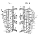
- Left frame rail 34 is provided with a pair of retaining flanges, 52,54 which are used to hold a first coreless tissue roll 56 and a second coreless tissue roll 58 about first spindle 30 and second spindle 32 respectively.
- Coreless tissue rolls generally have a relatively small central aperture 57 which may have a diameter of about 3 ⁇ 4 of an inch or so configured to fit around the spindles of sled 24 .
- the aperture has a diameter of about 5/8" or so.
- This type of tissue roll does not require any independent structure such as a cardboard or plastic cylinder and is advantageous inasmuch as more material can be placed on one roll and this method of dispensing tissue eliminates the wasteful core.
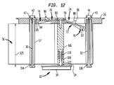
- FIGs 10 and 12 there is shown frame rail 34 in its open position 62 wherein tissue rolls may be placed about spindles 30 and 32 , that is to say the open position showing in Figures 10 and 12 is used to replenish the rolls of tissue on the sled.
- Right frame rail 36 is provided with a first latch dog assembly 70 as well as a second latch dog assembly 72.
- latch dog assembly 70 assumes a locking position 74 when a roll of tissue such as roll 56 is urged against the assembly by way of retaining flange 52; that is, it is secured in place by way of retaining flange 52 .
- latch dog 72 assumes an inward or release position 76 when there is insufficient tissue on roll 58 about spindle 32 to urge latch dog 72 assembly outwardly as would be the case for example when a full roll of tissue is in place. That is, when the tissue is depleted the latch dog assembly assumes release position 76 because it is inwardly biased.
- the latch dog assemblies are pivotally mounted about mounting pins 78,80 respectively and include gauge members 82 and 84 .
- Each of the gauge members is disposed a predetermined distance 86 from its associated spindle as can be seen in Figure 9 .
- the gauge member includes a terminal portion such as portions 92,94 that are generally arcuate in shape such that the distance between the gauge member and its associated spindle is relatively uniform when the latch dog assembly is in the locking position.
- Gauge member 82 is provided with a first latch dog projection 88 whereas gauge member 84 is provided with a second latch dog projection 90 .
- Latch dog projections 88,90 are configured as shown to cooperate with locking shoulder 28 of latch projection 26 to hold sled 24 in the upper position shown in Figure 1 when the latch dog assemblies are in their locking position and the sled is mounted in the tracks of the dispenser.
- Right frame rail 36 preferably includes a slot 96 and a slot 98 in which gauge members 82 and 84 respectively are mounted in the rail.
- the gauge members include a surface such as surface 85 that is generally contiguous with the inner surface of frame rail 36 when the latch dog assemblies are biased to their locking positions as is seen in Figures 7 and 12 , left side.
- Support sled 24 further includes a support bar 106 generally located between spindles 30, 32.
- the support bar has mounted therein a retaining pin 108 which is spring biased inwardly by way of spring 110 .
- Retaining pin 108 further includes a cross bar 120 which cooperates with the end of support bar 106 so that left frame rail 34 travels in generally helical motion when it is rotated for replenishing the dispenser.
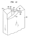
- the particular geometry of the end of support bar 106 will be appreciated by way of reference to Figures 11 and 12 .
- an end 121 of support bar 106 is provided with a pair of helical ramps 122 and 123 which cooperate with cross bar 120 to move it to an outer pair of slots 124, 126 upon rotation of frame rail 34 as shown in Figures 10 and 12 . That is to say the ramp will cause rail 34 to move outwardly increasing a distance 125 between the rails when the rail is in an open position. In this way loading of the rolls onto spindles 30,32 is facilitated since the rail moved helically outwardly as shown in Figures 10, 11 and 12 allows clearance for the rolls.
- each of the flanges 52,54 are provided with slots 130,132 so that they may be readily locked in position about the ends of spindles 30,32.
- each of the spindles projects outwardly with respect to a roll placed thereon and includes a channel, such as channels 134 and 136 respectively of spindles 30 and 32. These channels cooperate with the slots to lock rail 34 in a closed position before support sled 24 is placed in the dispenser.
- the support sled of the dispenser is configured such that it is generally symmetrical about an axis of rotation 138 , shown on Figure 6 .
- This feature is important in commercial installations because it is preferred to leave a partially consumed roll on its spindle and replace only rolls that are substantially exhausted.
- an attendant seeking to replenish the dispensers in a facility will simply remove the support sled from dispenser 10, move rail 34 to an open position and replace only the exhausted roll.
- the support sled is then rotated 180° and replaced in the dispenser such that the full roll is reserved in the upper dispensing position 150 as is shown in Figure 1. It is thus not necessary to remove a partially depleted roll when replenishing the dispenser.
- latch dog assembly When the roll is exhausted the latch dog assembly is biased inwardly by a leaf spring such as leaf spring 144 such that it moves to release position 76 upon exhaustion of the roll.
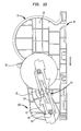
- the latch dog projection then moves inwardly as is shown in Figures 7 and 12 where latch dog projection 88 moves inwardly with respect to the support sled allowing it to travel to a lower dispensing position such as that seen in Figure 13.
- the dispenser of the invention is used for sequentially dispensing coreless rolls of tissue.
- a dispenser housing which has a guide track such as a first guide track such as 20 , of left sidewall 14 , and a guide track 22 of right sidewall 16 such that the sled is mounted for generally vertical motion between an upper dispensing position such as position 150 and a lower dispensing position such as 152 , the housing having an upper enclosure typically defined by a cover such as cover 12 for sequestering a reserved roll such as roll 56 in the upper dispensing position and being generally configured to expbse the reserve roll for dispensing in the lower dispensing position such as position 152.
- the housing further includes in one of its guide tracks a latch means such as latch projection 26 including a locking shoulder 28 .
- the support sled includes first and second spindles 30,32 adapted for receiving the rolls of coreless tissue.
- At least first and second frame rails support the spindles between the rails.
- the rails are further provided with guide surfaces such as guide surfaces 38 through 44 configured to cooperate with the guide tracks of the housing in which the support sled is mounted for guiding the support sled in generally vertical motion between an upper dispensing position and a lower dispensing position.
- At least one of the frame rails is moveable with respect to the first and second spindles of the support sled and includes a pair of retaining flanges such as flanges 52 and 54 for securing the rolls onto the support sled.
- the rolls are releasably secured about the first and second spindles of the support sled in retaining position 60 and maybe removed when the moveable frame rail is moved to an open position such as position 62 .
- a full roll is placed about a spindle, such as roll 56 shown in Figure 7 , and the left rail is in a closed or retaining position 60 , the roll bears upon surface 85 of gauge member 84 and forces assembly 70 and latch dog projection 90 outwardly to the locking position as shown in Figure 7 , the left side.
- a roll is depleted, such as depleted roll 58 shown on the right side of Figure 7 and in Figure 8
- the associated latch dog assembly moves inwardly as shown in Figures 7 and 8 and as further noted above under the influence of spring
- At least one of the frame rails is provided with an inwardly biased latch dog assembly disposed adjacent at least one of the first and second spindles.
- the inventive support sled contains two latch dogs which are inwardly biased by a single leaf spring.
- the latch dog assemblies are configured so that they are urged outwardly to a locking position upon disposing a roll of coreless tissue about its adjacent spindle and is biased inwardly to a release position 76 upon depletion of the roll of coreless tissue disposed about its adjacent spindle.
- the latch dog assembly of the support sled is adapted to cooperate with the locking shoulder of the dispenser to retain the support sled in the upper dispensing position while urged outwardly to its locking position and to allow movement of the support sled to the lower dispensing position upon movement of the locking surface of the latch dog assembly to its inner release position, thereby exposing the reserve roll of coreless tissue for dispensing.
- Support sled 224 includes a first spindle 230 , a second spindle 232 , a left frame rail 23 4, a right frame rail 236 provided with gauge members 282, 284 as was described above in connection with parts numbered 200 numerals lower.
- Further features included in the embodiment of Figure 14 include rotatable central portions 235, 237 of spindles 230, 232. Portions 235 and 237 are in the form of sleeves mounted about a pair of central shafts 239, 241 indicated in dashed lines.
- the sleeves extend over most of the length of the spindles; more than about 75 percent of their length and have beveled ends indicated at 243 , 245, 247 and 249 to ensure that the rotating central segments of the spindles do not snag the tissue. Without a rotating central portion, a roll of coreless tissues will tend to tighten up on the spindle and thus not dispense freely.
- the spindles are further provided with feet 251, 253 adapted to fit into slots 255, 257 of frame rail 236 as well as slotted knobs 259, 261 adapted to cooperate with slotted rail 234 .
- FIG. 14 Further refinements to the embodiment shown in Figure 14 include a two-piece support bar 306 made up of a first part 306(a) and a second part 306(b) having retaining features such as hooks 307 and slots 309 as well as rings 311, 312, 313, 314 and 315 to secure the parts together.
- a two-piece support bar 306 made up of a first part 306(a) and a second part 306(b) having retaining features such as hooks 307 and slots 309 as well as rings 311, 312, 313, 314 and 315 to secure the parts together.
- Each part 306(a), 306(b) includes a hemicylindrical channel 317, 319 with relieved portions 321, 323 as shown.
- the parts are configured to cooperate so that they are assembled about a shaft 311 molded integrally with rail 234 which is also provided with an integrally-formed positioning bar 313 .
- Spring 310 is positioned on shaft 311 between a movable ring 325 and a screw such that it urges rail 234 inwardly when the sled is assembled; that is, when bar 306 is assembled and positioned by way of molded-in pins 327, 329 and the other parts are secured in place, ring 325 fits in slot 335.
- relieved portions 321, 323 of channels 317 and 319 cooperate with positioning bar 313 to force it outwardly when rail 234 is rotated to the open position.
- portions 321, 323 have a maximum lateral projection in their intermediate portion so that the rotation of support rail 234 is bistable; that is, the rail is retained in either the fully open or fully closed position because of the shape of the relief portions in the respective channels.
Landscapes
- Health & Medical Sciences (AREA)
- Public Health (AREA)
- Replacement Of Web Rolls (AREA)
- Unwinding Webs (AREA)
- Absorbent Articles And Supports Therefor (AREA)
- Spinning Or Twisting Of Yarns (AREA)
- Closures For Containers (AREA)
- Details Of Rigid Or Semi-Rigid Containers (AREA)
Priority Applications (2)
| Application Number | Priority Date | Filing Date | Title |
|---|---|---|---|
| EP06005224A EP1665971B1 (fr) | 2001-12-20 | 2002-12-20 | Dispositif de cliquet de loquet à utiliser dans un distributeur |
| ES06005224T ES2304746T3 (es) | 2001-12-20 | 2002-12-20 | Conjunto de garras de enganche para utilizar en un dispensador. |
Applications Claiming Priority (4)
| Application Number | Priority Date | Filing Date | Title |
|---|---|---|---|
| US34294401P | 2001-12-20 | 2001-12-20 | |
| US342944P | 2001-12-20 | ||
| US322327 | 2002-12-18 | ||
| US10/322,327 US6752349B2 (en) | 2001-12-20 | 2002-12-18 | Support sled for rolls of absorbent sheet and dispenser incorporating same |
Related Child Applications (1)
| Application Number | Title | Priority Date | Filing Date |
|---|---|---|---|
| EP06005224A Division EP1665971B1 (fr) | 2001-12-20 | 2002-12-20 | Dispositif de cliquet de loquet à utiliser dans un distributeur |
Publications (2)
| Publication Number | Publication Date |
|---|---|
| EP1321084A1 true EP1321084A1 (fr) | 2003-06-25 |
| EP1321084B1 EP1321084B1 (fr) | 2006-06-21 |
Family
ID=26983359
Family Applications (1)
| Application Number | Title | Priority Date | Filing Date |
|---|---|---|---|
| EP02258905A Expired - Lifetime EP1321084B1 (fr) | 2001-12-20 | 2002-12-20 | Ensemble de support coulissant pour rouleaux de matériau en feuille absorbant et distributeur comportant un tel ensemble |
Country Status (8)
| Country | Link |
|---|---|
| US (1) | US6752349B2 (fr) |
| EP (1) | EP1321084B1 (fr) |
| AT (2) | ATE394061T1 (fr) |
| CA (1) | CA2414887C (fr) |
| DE (2) | DE60226521D1 (fr) |
| DK (1) | DK1321084T3 (fr) |
| ES (2) | ES2263746T3 (fr) |
| PT (1) | PT1321084E (fr) |
Cited By (4)
| Publication number | Priority date | Publication date | Assignee | Title |
|---|---|---|---|---|
| EP1656869A3 (fr) * | 2004-11-12 | 2009-10-21 | Georgia-Pacific Consumer Products LP | Distributeur pour papier enroulé |
| US10835086B2 (en) | 2018-04-09 | 2020-11-17 | Charles A. Osborne, JR. | Sheet material transfer system/assembly for a dispenser |
| EP3888513A1 (fr) * | 2020-04-01 | 2021-10-06 | San Jamar, Inc. | Distributeur pour de multiples rouleaux de matériau en bande |
| US11478111B2 (en) | 2019-06-14 | 2022-10-25 | Valve Solutions, Inc. | Loading and transfer system/assembly for sheet material dispensers |
Families Citing this family (43)
| Publication number | Priority date | Publication date | Assignee | Title |
|---|---|---|---|---|
| US7309042B2 (en) * | 2005-02-24 | 2007-12-18 | Pleo Originals, Llc | Automatic positioning dispenser for paper rolls |
| USD543402S1 (en) | 2005-11-09 | 2007-05-29 | Georgia-Pacific Consumer Products Lp | Tissue roll dispenser |
| USD556482S1 (en) | 2005-11-09 | 2007-12-04 | Georgia-Pacific Consumer Products Lp | Tissue roll dispenser cover |
| USD543745S1 (en) | 2005-11-09 | 2007-06-05 | Georgia-Pacific Consumer Products Lp | Tissue roll dispenser |
| PL2040595T3 (pl) * | 2006-07-07 | 2016-10-31 | Dozownik rolek | |
| RU2397689C1 (ru) * | 2006-07-07 | 2010-08-27 | Ска Хайджин Продактс Аб | Дозатор для рулонов |
| US7568652B2 (en) * | 2006-10-03 | 2009-08-04 | Georgia-Pacific Consumer Products Lp | Easy load sheet product dispenser |
| USD551475S1 (en) | 2006-10-03 | 2007-09-25 | Georgia-Pacific Consumer Products Lp | Dispenser housing |
| USD551474S1 (en) | 2006-10-03 | 2007-09-25 | Georgia-Pacific Consumer Products Lp | Dispenser housing |
| CA2664846C (fr) | 2006-10-03 | 2014-12-23 | Georgia-Pacific Consumer Products Lp | Distributeur automatique de produits de type feuilles |
| US7967235B2 (en) * | 2006-10-03 | 2011-06-28 | Sca Tissue North America Llc | Dispenser that automatically transfers rolls of absorbent material, method of reloading same, and rolls of absorbent material for use in same |
| USD572058S1 (en) | 2006-10-03 | 2008-07-01 | Georgia-Pacific Consumer Products Lp | Dispenser housing |
| USD547581S1 (en) | 2006-10-03 | 2007-07-31 | Georgia-Pacific Consumer Products Lp | Dispenser housing |
| US8162252B2 (en) | 2006-10-03 | 2012-04-24 | Georgia-Pacific Consumer Products Lp | Automated tissue dispenser |
| WO2012075504A1 (fr) * | 2010-12-03 | 2012-06-07 | Oasis Brands, Inc. | Ensemble chariot pour distributeurs séquentiels de produits de papier |
| US9138110B2 (en) * | 2011-07-25 | 2015-09-22 | Wausau Paper Towel & Tissue, Llc | Tissue dispenser, method for dispensing tissue, and tissue dispenser insert |
| AT512607B1 (de) | 2012-02-21 | 2015-08-15 | Hans Georg Hagleitner | Spendesystem |
| US9366649B2 (en) * | 2012-03-29 | 2016-06-14 | Owlstone Nanotech Inc | Field asymmetric ion mobility spectrometry system |
| US10123666B2 (en) | 2012-11-30 | 2018-11-13 | Gpcp Ip Holdings Llc | System and method for reducing waste using a sheet product dispenser |
| US10143340B2 (en) * | 2015-06-17 | 2018-12-04 | Essity Hygiene And Health Aktiebolag | Dispenser assembly and related methods |
| US11412900B2 (en) | 2016-04-11 | 2022-08-16 | Gpcp Ip Holdings Llc | Sheet product dispenser with motor operation sensing |
| US11395566B2 (en) | 2016-04-11 | 2022-07-26 | Gpcp Ip Holdings Llc | Sheet product dispenser |
| CA179934S (en) | 2018-02-23 | 2020-03-05 | Cascades Canada Ulc | Dispenser |
| CA179935S (en) | 2018-02-23 | 2020-03-05 | Cascades Canada Ulc | Dispenser |
| CA3035709C (fr) | 2018-03-09 | 2025-09-23 | Cascades Canada Ulc | Distributeur de materiau en bande et methode |
| CA181664S (en) | 2018-05-29 | 2021-03-08 | Cascades Canada Ulc | Paper dispenser |
| CA181663S (en) | 2018-05-29 | 2021-03-08 | Cascades Canada Ulc | Paper dispenser |
| CA181854S (en) | 2018-06-07 | 2020-03-05 | Cascades Canada Ulc | Paper dispenser |
| US11825993B2 (en) | 2018-07-09 | 2023-11-28 | Gpcp Ip Holdings Llc | Spindle and cover components for sheet product dispensers and dispenser systems including such components |
| US10743723B2 (en) | 2018-09-28 | 2020-08-18 | Gpcp Ip Holdings Llc | Spindle assembly for sheet product dispensers |
| US10952570B2 (en) | 2018-09-28 | 2021-03-23 | Gpcp Ip Holdings Llc | Spindles and dispensers for sheet product |
| WO2020123491A1 (fr) | 2018-12-12 | 2020-06-18 | Osborne Charles Agnew Jr | Ensemble de distribution destiné à distribuer sélectivement une pluralité de réserves de matériau en feuille roulé |
| US11395567B2 (en) * | 2019-03-28 | 2022-07-26 | Dispensing Dynamics International, Inc. | Automatic drop-down dispenser |
| EP3962335A4 (fr) * | 2019-04-30 | 2022-12-07 | Kimberly-Clark Worldwide, Inc. | Distributeur de produit en papier multirouleaux |
| BR112021022484A2 (pt) | 2019-07-05 | 2022-01-25 | Essity Hygiene & Health Ab | Dispensador e método de carregamento de um dispensador |
| AU2019471600B2 (en) * | 2019-10-31 | 2026-01-22 | Kimberly-Clark Worldwide, Inc. | Auto-drop dispenser |
| US11337567B2 (en) * | 2020-04-21 | 2022-05-24 | Kimberly-Clark Worldwide, Inc. | Dispenser with mechanical transfer and method |
| USD1011074S1 (en) * | 2021-05-31 | 2024-01-16 | Kimberly-Clark Worldwide, Inc. | Absorbent product dispenser |
| CA3248020A1 (fr) | 2022-02-08 | 2023-08-17 | Valve Solutions, Inc. | Ensemble distributeur de matériau en feuille pour distribuer sélectivement un matériau en feuille à partir d'une pluralité d'alimentations en matériau en feuille laminée |
| USD1118201S1 (en) | 2022-09-30 | 2026-03-17 | Vsi Health And Hygiene Group, Llc | Dispenser |
| USD1090103S1 (en) * | 2022-12-09 | 2025-08-26 | Essity Hygiene And Health Aktiebolag | Dispenser for toilet tissue |
| USD1090104S1 (en) | 2022-12-09 | 2025-08-26 | Essity Hygiene And Health Aktiebolag | Dispenser for toilet tissue |
| WO2025242316A1 (fr) * | 2024-05-24 | 2025-11-27 | Essity Hygiene And Health Aktiebolag | Agencement de distributeur |
Citations (9)
| Publication number | Priority date | Publication date | Assignee | Title |
|---|---|---|---|---|
| US3214014A (en) | 1963-04-23 | 1965-10-26 | Towlsaver Inc | Roll of strip material having a separable core structure |
| US3294329A (en) | 1964-01-27 | 1966-12-27 | Towlsaver Inc | Method and apparatus for dispensing strip material |
| US3381909A (en) | 1966-01-03 | 1968-05-07 | Towlsaver Inc | Apparatus for sequentially dispensing rolls of strip material |
| US3387902A (en) | 1967-01-03 | 1968-06-11 | Towlsaver Inc | Dispenser for sequentially dispensing rolls of tissue and the like |
| US3948454A (en) * | 1974-12-03 | 1976-04-06 | Scott Paper Company | Dispenser for multiple rolls of sheet material |
| US4143827A (en) | 1978-05-22 | 1979-03-13 | Towlsaver, Inc. | Roll holder for mounting split-core rolls of tissue in a dispenser |
| US4375874A (en) * | 1981-03-05 | 1983-03-08 | Bradley Corporation | Rolled tissue dispenser |
| US4662577A (en) * | 1982-02-09 | 1987-05-05 | Thomas Lewis | Toilet tissue dispenser |
| US5370336A (en) | 1993-06-04 | 1994-12-06 | James River Paper Company, Inc. | Dispenser apparatus for sequentially dispensing from coreless rolls of sheet material |
Family Cites Families (6)
| Publication number | Priority date | Publication date | Assignee | Title |
|---|---|---|---|---|
| US1919456A (en) * | 1929-07-08 | 1933-07-25 | Tribune Company | Roll stand for printing presses |
| US2549912A (en) * | 1947-04-21 | 1951-04-24 | Lionel G Lindsay | Supporting structure for a plurality of rolls |
| USD386025S (en) | 1996-09-30 | 1997-11-11 | James River Corporation Of Virginia | Toilet tissue dispenser |
| US5690299A (en) * | 1996-11-12 | 1997-11-25 | Perrin Manufacturing | Dispenser for feeding sheet material from sequential rolls |
| US5873542A (en) * | 1996-11-12 | 1999-02-23 | Perrin Manufacturing | Dispenser for feeding sheet material from sequential rolls |
| US6138939A (en) * | 1998-08-17 | 2000-10-31 | Kimberly Clark Worldwide, Inc. | Coreless adapter for dispensers of cored rolls of material |
-
2002
- 2002-12-18 US US10/322,327 patent/US6752349B2/en not_active Expired - Lifetime
- 2002-12-19 CA CA2414887A patent/CA2414887C/fr not_active Expired - Lifetime
- 2002-12-20 ES ES02258905T patent/ES2263746T3/es not_active Expired - Lifetime
- 2002-12-20 DE DE60226521T patent/DE60226521D1/de not_active Expired - Lifetime
- 2002-12-20 ES ES06005224T patent/ES2304746T3/es not_active Expired - Lifetime
- 2002-12-20 DE DE60212554T patent/DE60212554T2/de not_active Expired - Lifetime
- 2002-12-20 DK DK02258905T patent/DK1321084T3/da active
- 2002-12-20 AT AT06005224T patent/ATE394061T1/de active
- 2002-12-20 PT PT02258905T patent/PT1321084E/pt unknown
- 2002-12-20 AT AT02258905T patent/ATE330528T1/de active
- 2002-12-20 EP EP02258905A patent/EP1321084B1/fr not_active Expired - Lifetime
Patent Citations (9)
| Publication number | Priority date | Publication date | Assignee | Title |
|---|---|---|---|---|
| US3214014A (en) | 1963-04-23 | 1965-10-26 | Towlsaver Inc | Roll of strip material having a separable core structure |
| US3294329A (en) | 1964-01-27 | 1966-12-27 | Towlsaver Inc | Method and apparatus for dispensing strip material |
| US3381909A (en) | 1966-01-03 | 1968-05-07 | Towlsaver Inc | Apparatus for sequentially dispensing rolls of strip material |
| US3387902A (en) | 1967-01-03 | 1968-06-11 | Towlsaver Inc | Dispenser for sequentially dispensing rolls of tissue and the like |
| US3948454A (en) * | 1974-12-03 | 1976-04-06 | Scott Paper Company | Dispenser for multiple rolls of sheet material |
| US4143827A (en) | 1978-05-22 | 1979-03-13 | Towlsaver, Inc. | Roll holder for mounting split-core rolls of tissue in a dispenser |
| US4375874A (en) * | 1981-03-05 | 1983-03-08 | Bradley Corporation | Rolled tissue dispenser |
| US4662577A (en) * | 1982-02-09 | 1987-05-05 | Thomas Lewis | Toilet tissue dispenser |
| US5370336A (en) | 1993-06-04 | 1994-12-06 | James River Paper Company, Inc. | Dispenser apparatus for sequentially dispensing from coreless rolls of sheet material |
Cited By (7)
| Publication number | Priority date | Publication date | Assignee | Title |
|---|---|---|---|---|
| EP1656869A3 (fr) * | 2004-11-12 | 2009-10-21 | Georgia-Pacific Consumer Products LP | Distributeur pour papier enroulé |
| US10835086B2 (en) | 2018-04-09 | 2020-11-17 | Charles A. Osborne, JR. | Sheet material transfer system/assembly for a dispenser |
| US11478111B2 (en) | 2019-06-14 | 2022-10-25 | Valve Solutions, Inc. | Loading and transfer system/assembly for sheet material dispensers |
| US11864695B2 (en) | 2019-06-14 | 2024-01-09 | Valve Solutions, Inc. | Loading and transfer system/assembly for sheet material dispensers |
| US12161269B2 (en) | 2019-06-14 | 2024-12-10 | Valve Solutions, Inc. | Loading and transfer system/assembly for sheet material dispensers |
| EP3888513A1 (fr) * | 2020-04-01 | 2021-10-06 | San Jamar, Inc. | Distributeur pour de multiples rouleaux de matériau en bande |
| US11324361B2 (en) | 2020-04-01 | 2022-05-10 | San Jamar, Inc. | Dispenser for multiple rolls of web material |
Also Published As
| Publication number | Publication date |
|---|---|
| EP1321084B1 (fr) | 2006-06-21 |
| US20030146337A1 (en) | 2003-08-07 |
| CA2414887A1 (fr) | 2003-06-20 |
| DK1321084T3 (da) | 2006-10-23 |
| ES2263746T3 (es) | 2006-12-16 |
| ES2304746T3 (es) | 2008-10-16 |
| PT1321084E (pt) | 2006-08-31 |
| CA2414887C (fr) | 2011-03-15 |
| DE60212554T2 (de) | 2007-06-21 |
| DE60226521D1 (de) | 2008-06-19 |
| ATE330528T1 (de) | 2006-07-15 |
| US6752349B2 (en) | 2004-06-22 |
| DE60212554D1 (de) | 2006-08-03 |
| ATE394061T1 (de) | 2008-05-15 |
Similar Documents
| Publication | Publication Date | Title |
|---|---|---|
| US6752349B2 (en) | Support sled for rolls of absorbent sheet and dispenser incorporating same | |
| US5495997A (en) | Support apparatus for coreless toilet tissue roll | |
| US5314131A (en) | Apparatus for dispensing rolled flexible sheet material | |
| EP0758539B1 (fr) | Appareil de support pour rouleau sans noyau dans un distributeur de papier toilette | |
| CN105873485B (zh) | 纸巾分配器和用于分配纸巾的方法 | |
| US6607160B2 (en) | Easy loading dispenser | |
| CA2665143C (fr) | Distributeur transferant automatiquement des rouleaux de materiau absorbant, son procede de rechargement et rouleaux de materiau absorbant a utiliser dans celui-ci | |
| AU601340B1 (en) | Bathroom tissue dispenser (Spindle Release) | |
| US5915645A (en) | Loading device for dispensing apparatus for material wipes | |
| US5558302A (en) | Flexible sheet material dispenser with automatic roll transferring mechanism | |
| US7648098B2 (en) | Low reserve indicator for a paper towel dispenser | |
| US7546973B2 (en) | Low reserve indicator for a paper towel dispenser | |
| KR101159872B1 (ko) | 시트 재료의 다중 롤을 위한 분배기 | |
| WO1993004965A1 (fr) | Distributeur pour materiau en feuille flexible__________________ | |
| US10213070B2 (en) | Carriage assembly for sequential paper products dispensers | |
| EP0729724A1 (fr) | Système et méthode pour délivrer des produits de papier sous forme de rouleaux sans noyau | |
| US20130105618A1 (en) | Dispenser for a roll of absorbent paper tissue or nonwoven material | |
| GB2267271A (en) | Continuous dispensing of sheet from two rolls | |
| AU2002245729A1 (en) | Easy loading dispenser | |
| US5601253A (en) | Dispenser for rolled sheet material | |
| US20030080237A1 (en) | Coreless roll product adapter and dispenser | |
| EP1665971B1 (fr) | Dispositif de cliquet de loquet à utiliser dans un distributeur | |
| GB1583499A (en) | Dispenser for rolled strip material | |
| JPH0316555Y2 (fr) | ||
| MXPA97007003A (en) | Device for loading device for distributing materials of limpi |
Legal Events
| Date | Code | Title | Description |
|---|---|---|---|
| PUAI | Public reference made under article 153(3) epc to a published international application that has entered the european phase |
Free format text: ORIGINAL CODE: 0009012 |
|
| AK | Designated contracting states |
Designated state(s): AT BE BG CH CY CZ DE DK EE ES FI FR GB GR IE IT LI LU MC NL PT SE SI SK TR |
|
| AX | Request for extension of the european patent |
Extension state: AL LT LV MK RO |
|
| 17P | Request for examination filed |
Effective date: 20031229 |
|
| AKX | Designation fees paid |
Designated state(s): AT BE BG CH CY CZ DE DK EE ES FI FR GB GR IE IT LI LU MC NL PT SE SI SK TR |
|
| 17Q | First examination report despatched |
Effective date: 20050201 |
|
| GRAP | Despatch of communication of intention to grant a patent |
Free format text: ORIGINAL CODE: EPIDOSNIGR1 |
|
| GRAS | Grant fee paid |
Free format text: ORIGINAL CODE: EPIDOSNIGR3 |
|
| GRAA | (expected) grant |
Free format text: ORIGINAL CODE: 0009210 |
|
| AK | Designated contracting states |
Kind code of ref document: B1 Designated state(s): AT BE BG CH CY CZ DE DK EE ES FI FR GB GR IE IT LI LU MC NL PT SE SI SK TR |
|
| PG25 | Lapsed in a contracting state [announced via postgrant information from national office to epo] |
Ref country code: CZ Free format text: LAPSE BECAUSE OF FAILURE TO SUBMIT A TRANSLATION OF THE DESCRIPTION OR TO PAY THE FEE WITHIN THE PRESCRIBED TIME-LIMIT Effective date: 20060621 Ref country code: SI Free format text: LAPSE BECAUSE OF FAILURE TO SUBMIT A TRANSLATION OF THE DESCRIPTION OR TO PAY THE FEE WITHIN THE PRESCRIBED TIME-LIMIT Effective date: 20060621 |
|
| REG | Reference to a national code |
Ref country code: GB Ref legal event code: FG4D |
|
| REG | Reference to a national code |
Ref country code: CH Ref legal event code: EP |
|
| REG | Reference to a national code |
Ref country code: IE Ref legal event code: FG4D |
|
| REF | Corresponds to: |
Ref document number: 60212554 Country of ref document: DE Date of ref document: 20060803 Kind code of ref document: P |
|
| REG | Reference to a national code |
Ref country code: PT Ref legal event code: SC4A Effective date: 20060628 |
|
| REG | Reference to a national code |
Ref country code: GR Ref legal event code: EP Ref document number: 20060403005 Country of ref document: GR |
|
| REG | Reference to a national code |
Ref country code: SE Ref legal event code: TRGR |
|
| REG | Reference to a national code |
Ref country code: CH Ref legal event code: NV Representative=s name: A. BRAUN, BRAUN, HERITIER, ESCHMANN AG PATENTANWAE |
|
| REG | Reference to a national code |
Ref country code: DK Ref legal event code: T3 |
|
| REG | Reference to a national code |
Ref country code: ES Ref legal event code: FG2A Ref document number: 2263746 Country of ref document: ES Kind code of ref document: T3 |
|
| PG25 | Lapsed in a contracting state [announced via postgrant information from national office to epo] |
Ref country code: MC Free format text: LAPSE BECAUSE OF NON-PAYMENT OF DUE FEES Effective date: 20061231 |
|
| ET | Fr: translation filed | ||
| PLBE | No opposition filed within time limit |
Free format text: ORIGINAL CODE: 0009261 |
|
| STAA | Information on the status of an ep patent application or granted ep patent |
Free format text: STATUS: NO OPPOSITION FILED WITHIN TIME LIMIT |
|
| 26N | No opposition filed |
Effective date: 20070322 |
|
| REG | Reference to a national code |
Ref country code: CH Ref legal event code: PFA Owner name: FORT JAMES CORPORATION Free format text: FORT JAMES CORPORATION#133 PEACHTREE STREET, N.E.#ATLANTA, GEORGIA 30303 (US) -TRANSFER TO- FORT JAMES CORPORATION#133 PEACHTREE STREET, N.E.#ATLANTA, GEORGIA 30303 (US) |
|
| PG25 | Lapsed in a contracting state [announced via postgrant information from national office to epo] |
Ref country code: BG Free format text: LAPSE BECAUSE OF FAILURE TO SUBMIT A TRANSLATION OF THE DESCRIPTION OR TO PAY THE FEE WITHIN THE PRESCRIBED TIME-LIMIT Effective date: 20060921 Ref country code: EE Free format text: LAPSE BECAUSE OF FAILURE TO SUBMIT A TRANSLATION OF THE DESCRIPTION OR TO PAY THE FEE WITHIN THE PRESCRIBED TIME-LIMIT Effective date: 20060621 |
|
| PG25 | Lapsed in a contracting state [announced via postgrant information from national office to epo] |
Ref country code: LU Free format text: LAPSE BECAUSE OF NON-PAYMENT OF DUE FEES Effective date: 20061220 |
|
| PG25 | Lapsed in a contracting state [announced via postgrant information from national office to epo] |
Ref country code: CY Free format text: LAPSE BECAUSE OF FAILURE TO SUBMIT A TRANSLATION OF THE DESCRIPTION OR TO PAY THE FEE WITHIN THE PRESCRIBED TIME-LIMIT Effective date: 20060621 |
|
| PGFP | Annual fee paid to national office [announced via postgrant information from national office to epo] |
Ref country code: AT Payment date: 20101214 Year of fee payment: 9 Ref country code: DK Payment date: 20101210 Year of fee payment: 9 |
|
| PGFP | Annual fee paid to national office [announced via postgrant information from national office to epo] |
Ref country code: SK Payment date: 20101125 Year of fee payment: 9 |
|
| PGFP | Annual fee paid to national office [announced via postgrant information from national office to epo] |
Ref country code: GR Payment date: 20101221 Year of fee payment: 9 Ref country code: TR Payment date: 20101122 Year of fee payment: 9 |
|
| PGFP | Annual fee paid to national office [announced via postgrant information from national office to epo] |
Ref country code: CH Payment date: 20111227 Year of fee payment: 10 Ref country code: FI Payment date: 20111214 Year of fee payment: 10 Ref country code: SE Payment date: 20111223 Year of fee payment: 10 Ref country code: PT Payment date: 20111219 Year of fee payment: 10 Ref country code: NL Payment date: 20111228 Year of fee payment: 10 Ref country code: IE Payment date: 20111228 Year of fee payment: 10 |
|
| PGFP | Annual fee paid to national office [announced via postgrant information from national office to epo] |
Ref country code: BE Payment date: 20111229 Year of fee payment: 10 |
|
| REG | Reference to a national code |
Ref country code: PT Ref legal event code: MM4A Free format text: LAPSE DUE TO NON-PAYMENT OF FEES Effective date: 20130620 |
|
| BERE | Be: lapsed |
Owner name: *FORT JAMES CORP. Effective date: 20121231 |
|
| REG | Reference to a national code |
Ref country code: NL Ref legal event code: V1 Effective date: 20130701 |
|
| PG25 | Lapsed in a contracting state [announced via postgrant information from national office to epo] |
Ref country code: SE Free format text: LAPSE BECAUSE OF NON-PAYMENT OF DUE FEES Effective date: 20121221 |
|
| REG | Reference to a national code |
Ref country code: CH Ref legal event code: PL |
|
| REG | Reference to a national code |
Ref country code: AT Ref legal event code: MM01 Ref document number: 330528 Country of ref document: AT Kind code of ref document: T Effective date: 20121220 |
|
| REG | Reference to a national code |
Ref country code: DK Ref legal event code: EBP |
|
| PG25 | Lapsed in a contracting state [announced via postgrant information from national office to epo] |
Ref country code: PT Free format text: LAPSE BECAUSE OF NON-PAYMENT OF DUE FEES Effective date: 20130620 Ref country code: FI Free format text: LAPSE BECAUSE OF NON-PAYMENT OF DUE FEES Effective date: 20121220 |
|
| REG | Reference to a national code |
Ref country code: GR Ref legal event code: ML Ref document number: 20060403005 Country of ref document: GR Effective date: 20130703 |
|
| REG | Reference to a national code |
Ref country code: SK Ref legal event code: MM4A Ref document number: E 1374 Country of ref document: SK Effective date: 20121220 |
|
| REG | Reference to a national code |
Ref country code: IE Ref legal event code: MM4A |
|
| PG25 | Lapsed in a contracting state [announced via postgrant information from national office to epo] |
Ref country code: BE Free format text: LAPSE BECAUSE OF NON-PAYMENT OF DUE FEES Effective date: 20121231 |
|
| PG25 | Lapsed in a contracting state [announced via postgrant information from national office to epo] |
Ref country code: GR Free format text: LAPSE BECAUSE OF NON-PAYMENT OF DUE FEES Effective date: 20130703 Ref country code: SK Free format text: LAPSE BECAUSE OF NON-PAYMENT OF DUE FEES Effective date: 20121220 Ref country code: IE Free format text: LAPSE BECAUSE OF NON-PAYMENT OF DUE FEES Effective date: 20121220 Ref country code: CH Free format text: LAPSE BECAUSE OF NON-PAYMENT OF DUE FEES Effective date: 20121231 Ref country code: LI Free format text: LAPSE BECAUSE OF NON-PAYMENT OF DUE FEES Effective date: 20121231 Ref country code: NL Free format text: LAPSE BECAUSE OF NON-PAYMENT OF DUE FEES Effective date: 20130701 Ref country code: AT Free format text: LAPSE BECAUSE OF NON-PAYMENT OF DUE FEES Effective date: 20121220 |
|
| PG25 | Lapsed in a contracting state [announced via postgrant information from national office to epo] |
Ref country code: DK Free format text: LAPSE BECAUSE OF NON-PAYMENT OF DUE FEES Effective date: 20130102 |
|
| PGFP | Annual fee paid to national office [announced via postgrant information from national office to epo] |
Ref country code: GB Payment date: 20131218 Year of fee payment: 12 Ref country code: DE Payment date: 20131218 Year of fee payment: 12 |
|
| PG25 | Lapsed in a contracting state [announced via postgrant information from national office to epo] |
Ref country code: TR Free format text: LAPSE BECAUSE OF NON-PAYMENT OF DUE FEES Effective date: 20121220 |
|
| PGFP | Annual fee paid to national office [announced via postgrant information from national office to epo] |
Ref country code: ES Payment date: 20131112 Year of fee payment: 12 Ref country code: FR Payment date: 20131209 Year of fee payment: 12 Ref country code: IT Payment date: 20131211 Year of fee payment: 12 |
|
| REG | Reference to a national code |
Ref country code: DE Ref legal event code: R119 Ref document number: 60212554 Country of ref document: DE |
|
| GBPC | Gb: european patent ceased through non-payment of renewal fee |
Effective date: 20141220 |
|
| REG | Reference to a national code |
Ref country code: FR Ref legal event code: ST Effective date: 20150831 |
|
| PG25 | Lapsed in a contracting state [announced via postgrant information from national office to epo] |
Ref country code: GB Free format text: LAPSE BECAUSE OF NON-PAYMENT OF DUE FEES Effective date: 20141220 Ref country code: DE Free format text: LAPSE BECAUSE OF NON-PAYMENT OF DUE FEES Effective date: 20150701 |
|
| PG25 | Lapsed in a contracting state [announced via postgrant information from national office to epo] |
Ref country code: FR Free format text: LAPSE BECAUSE OF NON-PAYMENT OF DUE FEES Effective date: 20141231 |
|
| PG25 | Lapsed in a contracting state [announced via postgrant information from national office to epo] |
Ref country code: IT Free format text: LAPSE BECAUSE OF NON-PAYMENT OF DUE FEES Effective date: 20141220 |
|
| REG | Reference to a national code |
Ref country code: ES Ref legal event code: FD2A Effective date: 20160531 |
|
| PG25 | Lapsed in a contracting state [announced via postgrant information from national office to epo] |
Ref country code: ES Free format text: LAPSE BECAUSE OF NON-PAYMENT OF DUE FEES Effective date: 20141221 |