EP1321177A2 - Adsorbant, module de filtration, unité de filtration et installation de purification des gaz bruts - Google Patents
Adsorbant, module de filtration, unité de filtration et installation de purification des gaz bruts Download PDFInfo
- Publication number
- EP1321177A2 EP1321177A2 EP02028391A EP02028391A EP1321177A2 EP 1321177 A2 EP1321177 A2 EP 1321177A2 EP 02028391 A EP02028391 A EP 02028391A EP 02028391 A EP02028391 A EP 02028391A EP 1321177 A2 EP1321177 A2 EP 1321177A2
- Authority
- EP
- European Patent Office
- Prior art keywords
- adsorber
- air
- filter
- filter module
- filter element
- Prior art date
- Legal status (The legal status is an assumption and is not a legal conclusion. Google has not performed a legal analysis and makes no representation as to the accuracy of the status listed.)
- Granted
Links
Images


Classifications
-
- B—PERFORMING OPERATIONS; TRANSPORTING
- B01—PHYSICAL OR CHEMICAL PROCESSES OR APPARATUS IN GENERAL
- B01D—SEPARATION
- B01D53/00—Separation of gases or vapours; Recovering vapours of volatile solvents from gases; Chemical or biological purification of waste gases, e.g. engine exhaust gases, smoke, fumes, flue gases, aerosols
- B01D53/02—Separation of gases or vapours; Recovering vapours of volatile solvents from gases; Chemical or biological purification of waste gases, e.g. engine exhaust gases, smoke, fumes, flue gases, aerosols by adsorption, e.g. preparative gas chromatography
- B01D53/04—Separation of gases or vapours; Recovering vapours of volatile solvents from gases; Chemical or biological purification of waste gases, e.g. engine exhaust gases, smoke, fumes, flue gases, aerosols by adsorption, e.g. preparative gas chromatography with stationary adsorbents
- B01D53/0407—Constructional details of adsorbing systems
- B01D53/0415—Beds in cartridges
-
- B—PERFORMING OPERATIONS; TRANSPORTING
- B01—PHYSICAL OR CHEMICAL PROCESSES OR APPARATUS IN GENERAL
- B01D—SEPARATION
- B01D53/00—Separation of gases or vapours; Recovering vapours of volatile solvents from gases; Chemical or biological purification of waste gases, e.g. engine exhaust gases, smoke, fumes, flue gases, aerosols
- B01D53/02—Separation of gases or vapours; Recovering vapours of volatile solvents from gases; Chemical or biological purification of waste gases, e.g. engine exhaust gases, smoke, fumes, flue gases, aerosols by adsorption, e.g. preparative gas chromatography
- B01D53/04—Separation of gases or vapours; Recovering vapours of volatile solvents from gases; Chemical or biological purification of waste gases, e.g. engine exhaust gases, smoke, fumes, flue gases, aerosols by adsorption, e.g. preparative gas chromatography with stationary adsorbents
- B01D53/0407—Constructional details of adsorbing systems
- B01D53/0446—Means for feeding or distributing gases
-
- B—PERFORMING OPERATIONS; TRANSPORTING
- B01—PHYSICAL OR CHEMICAL PROCESSES OR APPARATUS IN GENERAL
- B01D—SEPARATION
- B01D2253/00—Adsorbents used in seperation treatment of gases and vapours
- B01D2253/10—Inorganic adsorbents
- B01D2253/102—Carbon
-
- B—PERFORMING OPERATIONS; TRANSPORTING
- B01—PHYSICAL OR CHEMICAL PROCESSES OR APPARATUS IN GENERAL
- B01D—SEPARATION
- B01D2259/00—Type of treatment
- B01D2259/40—Further details for adsorption processes and devices
- B01D2259/40011—Methods relating to the process cycle in pressure or temperature swing adsorption
- B01D2259/40077—Direction of flow
- B01D2259/40081—Counter-current
-
- B—PERFORMING OPERATIONS; TRANSPORTING
- B01—PHYSICAL OR CHEMICAL PROCESSES OR APPARATUS IN GENERAL
- B01D—SEPARATION
- B01D2259/00—Type of treatment
- B01D2259/40—Further details for adsorption processes and devices
- B01D2259/40083—Regeneration of adsorbents in processes other than pressure or temperature swing adsorption
- B01D2259/40086—Regeneration of adsorbents in processes other than pressure or temperature swing adsorption by using a purge gas
-
- B—PERFORMING OPERATIONS; TRANSPORTING
- B01—PHYSICAL OR CHEMICAL PROCESSES OR APPARATUS IN GENERAL
- B01D—SEPARATION
- B01D2259/00—Type of treatment
- B01D2259/40—Further details for adsorption processes and devices
- B01D2259/40083—Regeneration of adsorbents in processes other than pressure or temperature swing adsorption
- B01D2259/40088—Regeneration of adsorbents in processes other than pressure or temperature swing adsorption by heating
- B01D2259/40096—Regeneration of adsorbents in processes other than pressure or temperature swing adsorption by heating by using electrical resistance heating
Definitions
- the invention relates to an adsorber for cleaning raw gases according to the preamble of claim 1, a filter module with a such adsorber according to the preamble of claim 10, a filter unit with such a filter module according to the preamble of Claim 16, a system for outdoor air treatment with a such filter module according to the preamble of claim 18 and a system for exhaust air treatment with such a filter module according to the preamble of claim 21.
- the invention has for its object the generic adsorber, the generic filter module, the generic filter unit and to train the generic systems so that the Raw gas can be optimally cleaned in a simple manner.
- the filter material of the adsorber consists of an electrically conductive Adsorber. With it, those in the raw gas can unwanted components can be retained very easily.
- the electrically conductive adsorber material can also can be easily regenerated simply by using regeneration air in reverse Direction of flow through the adsorber material becomes.
- ACF filters are used that are made from an activated carbon fiber fabric or fleece exist. When the raw gas passes through these adsorbers the pollutants get stuck and can be in a regeneration process be removed again. For fast, safe and controlled regeneration, the adsorber material is controlled by control technology Process heated electrically and with purge air or Regeneration air flows through.
- the adsorber according to the invention can in ventilation systems for the treatment of outside air and solvents or odor-laden exhaust air can be used.
- FIG. 1 shows an example of a filter unit 1 of an exhaust air or outside air system.
- the filter unit is in the illustrated embodiment of nine modules 2, in terms of type and size are advantageously identical.
- the number of filter units 1 The modules used depend on the volume flow required in each case Use case.
- Each module 2 has on its front 3 and on its back 4 each have at least one inlet opening 5 and one outlet opening 6 (Fig. 5).
- At the inlet and outlet openings 5, 6 is in each case an air flap unit 7, 8 (Fig. 1 and 5) arranged.
- This Air flap units 7, 8 have air flaps lying parallel to one another 9, 10, which are opened via (not shown) servomotors or can be closed.
- the air flaps 9, 10 allow a ventilation separation of the filter modules 2 from the whole Airflow from the filter unit 1.
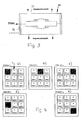
- each module 2 there is a function of the size of the air flow Number of cartridges 11 provided (Fig. 2 and 5). How to 5 to 10 results, the cartridge 11 has an axis 12 which is formed by a tube that is in the area between two on the Axis 12 fixed floors 13, 14 is perforated. The two floors 13, 14 form end caps of the cartridge 11.
- the end caps have, like for the end cover 13 in Fig. 6, a central opening 15, the edge 16 of which is bent inwards at right angles and for receiving an annular seal 17 is used. It consists of a thermal resistant and electrically non-conductive material and has a Internal thread 18 so that the ring seal 17 on the external thread 19 of the axis end can be screwed.
- the ring seal 17 protrudes over the peripheral edge 15 of the bottom 13 and has one this edge 15 overlapping, radially outwardly directed ring flange 20.
- the angled edge 16 of the base 13 lies on it sealing.
- the outer edge 29, 30 (FIGS. 7 and 8) of the two floors 13, 14 is bent at right angles so that a circumferential ring is formed an ACF fabric 31 or an ACF nonwoven can be wound.
- the edges 29, 30 lying in alignment with one another have (not shown) Mandrels for this fabric or fleece 31. It can wound in several layers on the angled edges 29, 30 become.
- the distance between the two floors 13, 14 can be changed and in this way the fabric 31 can be stretched in the axial direction.
- the Shell of the cartridge 11 is formed by the wound ACF fabric 31. It is also possible to use the ACF fabric 31 or the ACF fleece to wrap on a cylindrical support that is not electrically conductive, air-permeable material. For one example, a glass fiber fabric can be used for the carrier. This carrier is angled on the outside in the same way Edge 29, 30 of the bottoms 13, 14 fastened like the ACF fabric 31.
- This floor 14 can be designed for example in the form of a spoke wheel.
- the module 2 has a cuboid housing 35, for example can consist of metal.
- the housing 35 are depending on the size of the Airflow one or more cartridges 11 lying parallel next to each other arranged. In the illustrated embodiment, in one Row three cartridges 11 spaced one above the other. Further cartridges are spaced apart from that in FIG. 5 cartridge series shown. All cartridges 11 have the described training.
- Adjacent cartridges 11 of a row are electrical, as shown in FIG. 7 connected in series. The connection is made via the electrical conductive floors 13 of the adjacent cartridges 11. Da the cartridges 11 are electrically connected in series, the electrical Resistance of the cartridges 11 increased and the current reduced. The voltage is regulated via a (not shown) Power controller, which is advantageously a controllable three-phase power supply Has.
- the bottom 37 and the ceiling 36 of the module housing 35 can be double-walled be trained.
- the front wall 3 and the rear wall 4 can be double-walled.
- the end caps 14 of the cartridges 11 are on one Partition 38 attached, which is between the floor 37 and the ceiling 36 extends. It has for those exiting through the end cover 14 corresponding air through openings.
- the air flap unit 7 consists of two parts 7 'and 7 ".
- the part 7 " is adjacent to the housing cover 36 and has only one Air flap 10.
- the other part 7 ' consists of several, in parallel stacked air flaps 10. Both parts 7 'and 7 " are through an intermediate wall 39 of the front wall 3 of the module housing 35 separated from each other.
- the air flap unit 8 on the rear 4 of the module housing 36 consists of two parts 8 'and 8 ". They are in the illustrated embodiment the same design as the parts 7 ', 7 "of the air flap unit 7, but offset by 180 ° with respect to this.
- the air flaps 9, 10 of all parts 7 ', 7 "and 8', 8" are parallel to each other.
- the adsorption principle of the cartridge filter is shown in FIG 11 explained in more detail.
- adsorption At a phase boundary, for example gaseous-solid, there can be a Increasing the concentration of one phase, for example the gaseous phase, come what is called adsorption.
- the interface between the two phases is decisive. Will not be a chemical Reaction triggered during adsorption is called an physical adsorption, in which at least the heat of condensation appropriate heat is released.
- an adsorption For separating gases and steam from damp air is particularly suitable for coal good because it is unpolarized due to its electron configuration.
- the strength of the adsorption depends on the physical properties of the substance to be adsorbed. Hydrogen, oxygen, nitrogen are not adsorbed at normal temperature, so that the Coal as a filter medium does not contain unintentionally adsorbed substances is loaded.
- ACF filtration activate carbon fiber
- the filter cartridge is in the adsorption phase loaded while unloading in the desorption phase becomes.
- the gas to be cleaned the So-called raw gas, passed through the cartridges 11 and cleaned in the process.
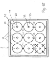
- Fig. 2 shows the flow direction of the raw gas, which initially in radial direction from the outside meets the ACF fabric 31 and here flows through the fabric.
- the raw gas flows radially inwards from the outside.
- the raw gas then flows within the cartridge 11 in the axial direction and emerges from the bottom 14 of the cartridge 11 Clean gas out.
- the opposite bottom 13 of the cartridge 11 is airtight, so that it is ensured that the Tissue 31 only inwardly entering tissue 11 into the cartridge can emerge through the openings in the bottom 14.
- the ACF fabric 31 may be in five to fifteen layers, for example the described manner on the angled outer edges 29, 30 of the floors 13, 14 are wound.
- the activated carbon fiber accumulates during the adsorption process 31 with the adsorbed substances. That of the inflowing from the outside
- the air-facing layer is enriched more than Layers of fabric 31 lying deeper in the direction of flow.
- the Concentration value in the purified air - depends on adsorption Desorption mode switched. Doing so will be more descriptive Way the air flaps 9, 10 of the air flap units 7, 8 switched so that a regeneration air flow through the ACF tissue flows in the opposite direction (Fig. 3). The amount of desorption air can be much smaller compared to the amount of adsorption his.
- the ACF fabric 31 is electrically Electricity heated. These are on the opposite floors 13, 14 of the cartridge 11 electrical connections are provided, wherein the cartridges lying one above the other advantageously via an electrical one Connection 40 connected together at their bottoms 13 (Fig. 7) become.
- the bottoms 14 of the adjacent cartridges are also connected 41 electrically connected to each other (Fig. 10).
- the current flows in the longitudinal direction of the cartridge 11 exclusively through the electrically conductive fibers of the ACF fabric 31.
- the current is so regulated that the fibers of the fabric 31 to the desired Warm the desorption temperature, for example to 200 ° C.
- the flow is adjusted so that the concentration in the desorption air flow desired values, for example 25% LEL, are not exceeds. Only then is the desorption airflow advantageous switched on when the fabric 31 has a certain temperature.
- FIG. 3 shows, the cartridges 11 during the desorption phase in reverse to the adsorption phase according to FIG. 2 Flow through with gas. It occurs through the openings in the Bottom 14 axially into the cartridge 11 and then occurs in the radial direction after flowing through the ACF fabric 31 radially outwards.
- the gases bound in tissue 31 during the adsorption phase become successively released again and as exhaust air either outdoors promoted or sent to another treatment stage.
- the adsorption and desorption or regeneration of the cartridges 11 are via the airtight flaps 9, 10 of the air flap units 7, 8 controlled at the inlet and outlet openings 5, 6 of the filter modules 2 are provided.
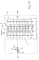
- FIG. 4 shows schematically in matrix form the regeneration of a filter unit 1 at different times.
- the filter unit 1 has nine modules 2, for example, which are arranged in three rows one above the other.
- the first module, designated RG is regenerated, while the cartridges of the remaining modules are in the adsorption phase.
- the air flaps are switched in a manner to be described in such a way that the second module is switched into the desorption or regeneration phase.
- the remaining modules are in the adsorption cycle.
- the third module is switched to the regeneration phase at a time t 3 , while the cartridges of the other modules are in the adsorption phase.
- the fourth module is switched to the regeneration phase.
- the individual modules can be switched to the regeneration phase in succession while the other modules are in the adsorption phase.
- Switching the individual modules into the regeneration phase takes place depending on the amount of exhaust gas to be treated and the exhaust gas concentration advantageous cyclical.
- a filter module 2 from Raw gas flow separated and after reaching the required operating temperature of for example 200 ° C via a purge air flow, cleaned as described with reference to FIG. 3.
- the loaded regeneration air flow which, for example, only 1/20 to 1/200 of the raw air flow is transported outside via its own pipe network.
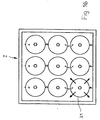
- FIG. 15 An advantageous arrangement with three groups of cartridges each electrically connected in series 11, which are each arranged in a filter module 2, is shown in FIG. 15. Here are the three rows above and below each other Cartridges 11 shown in front view. You have circular Outline and are on the electrical connections 40, 41 with each other connected. In the illustrated embodiment, they are one above the other lying cartridges 11 electrically connected to each other.
- Fig. 16 shows the case that the filter module 2 in the desorption phase has been switched.
- the gas flows in reverse Direction, radially outwards in the exemplary embodiment the ACF fabric 31.
- FIG. 17 shows a front view the air flap unit 7 with the two parts 7 'and 7 ".
- the one above lying part 7 "with the single air flap 9 is much shorter than the underlying part 7 'with a plurality of air flaps 9.
- the two parts 8 ', 8 "of the air flap unit 8 formed on the rear 4 of the module housing 35.
- FIG. 11 shows the filter module 2 according to FIG. 5 in the desorption phase.
- the two air flap units 7, 8 are so switched that the two air flaps 9 and 10 of the parts 7 “and 8" the air flap units 7 and 8 opened and the air flaps 9, 10 the parts 7 ', 8' are closed.
- the regeneration air fed Over the open air flap part 8 "on the rear 4 of the housing module 35 is the regeneration air fed. After passing through, it flows through the open one Air flap 10 of part 8 "in a channel 42 which is close to extends to the intermediate wall 38 of the module housing 35 and in the a distribution line 43 opens vertically. It extends vertically to the axis of the cartridge 11, whose axes 12 to the distribution line 43 are connected.
- Regeneration air thus flows into the distribution line via the duct 42 43 and from there into axes 12. Your other, the air damper unit 7 facing end is closed.
- the regeneration air thus flows in the area between the two end caps 13, 14 through the openings of the perforated tube 12 radially outwards.
- the air flaps 9, 10 of the parts 7 ', 8 'of the air flap units 7, 8 opened while the two air flaps 9, 10 of the air flap parts 7 ", 8" are closed.
- the Raw gas thus passes through the open air flaps 9 of the air flap part 7 'into the module housing, flows between adjacent ones Cartridges 11 axially and enters radially through the ACF fabric 31 Cartridges.
- the cleaned gas then flows in the area between the axis 12 and the ACF fabric 31 axially to End plate 14 and exits through its openings.
- the opened air flaps 10 of the air flap part 8 'then flows the clean gas from the module housing 35.
- FIG. 14 shows the filter module 2 according to FIG. 12 in the desorption phase.
- the Air flaps 9, 10 of parts 7 ', 8' of air flap units 7, 8 closed, while the air flap 9, 10 of the air flap parts 7 “, 8" is open.
- the regeneration air is through the air flap part 8 " passed into the module housing 35.
- no line 42, 43 is provided on the air flap part 8 ′′, with which the regeneration air to the individual cartridges 11 is directed.
- the regeneration air flows behind the air damper unit 8 to the end plates 14 of the cartridges 11 and flows through their openings into the respective cartridge.
- the air flap parts 7 ", 8" each with only a single air flap 9, 10 provided. It is of course possible, also the air flap parts 7 ", 8" with more to be provided as an air damper. In this case, the air flaps close the corresponding entry opening in the closed position airtight.
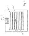
- FIG. 18 shows a schematic representation of a plant for processing of outside air.
- the filter module 2 the example with nine Cartridges 11 is provided, an outdoor air device 45 is connected upstream, via which the raw gas is fed to the filter module 2. Training of the outdoor air device 45 is known and is therefore not described in more detail. It has an air damper unit on the inlet side 46, which is followed by an air heater 47. Followinged him are two filters 48, a further air heater 49 and a cooling unit 50. The raw gas still flows through an outside air device 46 further cooling unit 51, a condenser 52, an air heater 53 and a blower 54 in the filter module 2.
- the blower 54 is each a silencer 55 upstream and downstream.
- the raw gas supplied is based on the of the previous embodiments described by the cartridges 11 out, the unwanted in the raw gas Components are retained in the ACF fabric 31.
- the cleaned raw gas then passes through the air flap unit as clean gas 8 outwards.
- the filter module 2 is otherwise the same as in the embodiment according to Fig. 18.
- the air flaps are the air flap units 7, 8 each can be driven by a motor independently. This makes it possible to have 2 individual cartridges within the filter module 11 by switching appropriately from the adsorption process take out and regenerate while through the other cartridges the raw gas continues to flow. It is on this Possible in succession, as has been described with reference to FIG. 4 to regenerate the necessary cartridges without to have to interrupt the adsorption process.
- the cartridges 11 can also be used the ACF fabric is ideal for both outside air treatment and use for exhaust air treatment.
Landscapes
- Chemical & Material Sciences (AREA)
- Engineering & Computer Science (AREA)
- Analytical Chemistry (AREA)
- General Chemical & Material Sciences (AREA)
- Oil, Petroleum & Natural Gas (AREA)
- Chemical Kinetics & Catalysis (AREA)
- Separation Of Gases By Adsorption (AREA)
- Separation Using Semi-Permeable Membranes (AREA)
- Filtering Materials (AREA)
Applications Claiming Priority (2)
| Application Number | Priority Date | Filing Date | Title |
|---|---|---|---|
| DE10164461 | 2001-12-21 | ||
| DE10164461A DE10164461A1 (de) | 2001-12-21 | 2001-12-21 | Adsorber zur Reinigung von Rohgasen, Filtermodul mit einem solchen Adsorber, Filtereinheit mit wenigstens zwei solchen Filtermodulen und Anlage zur Außenluftaufbereitung bzw. zur Fortluftbehandlung mit solchen Filtermodulen |
Publications (3)
| Publication Number | Publication Date |
|---|---|
| EP1321177A2 true EP1321177A2 (fr) | 2003-06-25 |
| EP1321177A3 EP1321177A3 (fr) | 2004-01-14 |
| EP1321177B1 EP1321177B1 (fr) | 2007-08-22 |
Family
ID=7711132
Family Applications (1)
| Application Number | Title | Priority Date | Filing Date |
|---|---|---|---|
| EP02028391A Expired - Lifetime EP1321177B1 (fr) | 2001-12-21 | 2002-12-18 | Adsorbant de purification des gaz bruts |
Country Status (5)
| Country | Link |
|---|---|
| US (1) | US6939395B2 (fr) |
| EP (1) | EP1321177B1 (fr) |
| CN (1) | CN100488597C (fr) |
| AT (1) | ATE370783T1 (fr) |
| DE (2) | DE10164461A1 (fr) |
Cited By (1)
| Publication number | Priority date | Publication date | Assignee | Title |
|---|---|---|---|---|
| EP2643072B1 (fr) * | 2010-11-24 | 2021-12-29 | Eisenmann SE | Dispositif de filtration et procédé de nettoyage d'un courant de gaz |
Families Citing this family (5)
| Publication number | Priority date | Publication date | Assignee | Title |
|---|---|---|---|---|
| KR20060026319A (ko) * | 2004-09-20 | 2006-03-23 | 삼성전자주식회사 | 모듈형 공기청정기 |
| EP1669126A1 (fr) * | 2004-12-08 | 2006-06-14 | Mann + Hummel ProTec GmbH | Systeme de sechage a dessicant utilisant des zones d'absorption séquentielles |
| DE102007056667A1 (de) | 2007-11-24 | 2009-05-28 | Dr. Ing. H.C. F. Porsche Aktiengesellschaft | Filtereinrichtung |
| US20110132197A1 (en) * | 2008-08-29 | 2011-06-09 | Honda Motor Co., Ltd. | Exhaust recycle system |
| RU2471536C1 (ru) * | 2011-10-10 | 2013-01-10 | Олег Савельевич Кочетов | Вертикальный адсорбер кочетова |
Family Cites Families (32)
| Publication number | Priority date | Publication date | Assignee | Title |
|---|---|---|---|---|
| US3577705A (en) * | 1968-12-23 | 1971-05-04 | Hitco | Filter system |
| US3850785A (en) * | 1971-10-21 | 1974-11-26 | Us Army | Reinforced carbon fabrics |
| GB1429476A (en) * | 1972-07-05 | 1976-03-24 | Secr Defence | Filter assemblies |
| GB1456231A (en) * | 1973-02-28 | 1976-11-24 | Secr Defence | Adsorptive devices |
| US3883328A (en) * | 1973-11-29 | 1975-05-13 | Raymond G Spain | Carbon fiber electrodes for electrical precipitators |
| US4181513A (en) * | 1974-11-05 | 1980-01-01 | Toyobo Co., Ltd. | Carbon adsorptive filter material with layers of reinforcing non woven fabrics needle punched |
| JPS5198679A (fr) * | 1975-02-26 | 1976-08-31 | ||
| US4217386A (en) * | 1979-06-07 | 1980-08-12 | The United States Of America As Represented By The Secretary Of The Army | Laminated, highly sorbent, active carbon fabric |
| US4565727A (en) * | 1983-09-12 | 1986-01-21 | American Cyanamid Co. | Non-woven activated carbon fabric |
| US4842909A (en) * | 1986-01-24 | 1989-06-27 | Brassell Gilbert W | Container for storing liquids comprising carbon-carbon composites |
| US4938869A (en) * | 1988-10-19 | 1990-07-03 | Bay-San Co., Inc. | Spiral wound filter element |
| DE3911826A1 (de) * | 1989-04-11 | 1990-10-31 | Seitz Filter Werke | Filterkerze bzw. filtermodul aus flexiblem tiefenfiltermaterial |
| JPH0733875Y2 (ja) * | 1989-05-08 | 1995-08-02 | 臼井国際産業株式会社 | 排気ガス浄化装置 |
| DE4104513C2 (de) * | 1990-02-14 | 1996-11-28 | Chmiel Horst | Adsorber |
| FR2691234A1 (fr) * | 1992-05-14 | 1993-11-19 | Omia | Procédé de destruction par pyrolyse de particules en suspension. |
| US5980616A (en) * | 1993-02-16 | 1999-11-09 | Donaldson Company, Inc. | Filter media for preventing carbon migration |
| US5772738A (en) * | 1993-11-30 | 1998-06-30 | Purex Co., Ltd. | Multifunctional air filter and air-circulating clean unit with the same incorporated therein |
| DE19613326A1 (de) * | 1995-04-08 | 1996-10-10 | Gewerk Keramchemie | Vorrichtung zur Rückgewinnung von Lösemitteln |
| US5972253A (en) * | 1996-09-30 | 1999-10-26 | University Of Kentucky Research Foundation | Preparation of monolithic carbon fiber composite material |
| US5912423A (en) * | 1997-01-23 | 1999-06-15 | Calgon Carbon Corporation | Method and means for purifying air with a regenerable carbon cloth sorbent |
| US5925168A (en) * | 1997-01-31 | 1999-07-20 | Judkins; Roddie R. | Method and apparatus for separating gases based on electrically and magnetically enhanced monolithic carbon fiber composite sorbents |
| US5827355A (en) * | 1997-01-31 | 1998-10-27 | Lockheed Martin Energy Research Corporation | Carbon fiber composite molecular sieve electrically regenerable air filter media |
| US5912424A (en) * | 1997-03-31 | 1999-06-15 | Lockheed Martin Energy Research Corporation | Electrical swing adsorption gas storage and delivery system |
| US5976471A (en) * | 1997-04-16 | 1999-11-02 | Lockheed Martin Energy Systems, Inc. | Ozone decomposing filter |
| US5980612A (en) * | 1998-01-21 | 1999-11-09 | Compliance Environmental Management, Inc. | Adsorbent activated carbon fiber sheet filter and method of regeneration |
| DE19828593A1 (de) * | 1998-04-07 | 1999-10-14 | Andreas Noack | Adsorptionsvorrichtung zur Fluidreinigung ausgestattet mit Mitteln zur Regeneration des adsorbierenden Materials |
| DE19823611B4 (de) * | 1998-05-27 | 2005-06-09 | Eads Deutschland Gmbh | Vorrichtung zur Reinigung eines dem Personeninnenraum eines Fahrzeuges zuzuführenden Luftstroms |
| US6068771A (en) * | 1999-02-11 | 2000-05-30 | Koch Membrane Systems, Inc. | Method for sealing spiral wound filtration modules |
| US6364936B1 (en) * | 2000-05-15 | 2002-04-02 | The Board Of Trustees Of The University Of Illinois | Selective sorption and desorption of gases with electrically heated activated carbon fiber cloth element |
| US6454834B1 (en) * | 2000-08-01 | 2002-09-24 | 3M Innovative Properties Company | Regenerable air cleaning device |
| IT1319521B1 (it) * | 2000-12-12 | 2003-10-20 | Sogefi Filtration Spa | Massa filtrante in foglio per filtro aria di ambiente,in particolaredi abitacolo di automezzi,e procedimenti per ottenere la stessa. |
| US6497754B2 (en) * | 2001-04-04 | 2002-12-24 | Constantinos J. Joannou | Self ionizing pleated air filter system |
-
2001
- 2001-12-21 DE DE10164461A patent/DE10164461A1/de not_active Withdrawn
-
2002
- 2002-12-18 AT AT02028391T patent/ATE370783T1/de active
- 2002-12-18 EP EP02028391A patent/EP1321177B1/fr not_active Expired - Lifetime
- 2002-12-18 DE DE50210747T patent/DE50210747D1/de not_active Expired - Lifetime
- 2002-12-20 CN CNB021575584A patent/CN100488597C/zh not_active Expired - Fee Related
- 2002-12-20 US US10/248,139 patent/US6939395B2/en not_active Expired - Fee Related
Cited By (1)
| Publication number | Priority date | Publication date | Assignee | Title |
|---|---|---|---|---|
| EP2643072B1 (fr) * | 2010-11-24 | 2021-12-29 | Eisenmann SE | Dispositif de filtration et procédé de nettoyage d'un courant de gaz |
Also Published As
| Publication number | Publication date |
|---|---|
| US6939395B2 (en) | 2005-09-06 |
| DE50210747D1 (de) | 2007-10-04 |
| DE10164461A1 (de) | 2003-07-03 |
| US20030136266A1 (en) | 2003-07-24 |
| ATE370783T1 (de) | 2007-09-15 |
| EP1321177A3 (fr) | 2004-01-14 |
| EP1321177B1 (fr) | 2007-08-22 |
| CN100488597C (zh) | 2009-05-20 |
| CN1426829A (zh) | 2003-07-02 |
Similar Documents
| Publication | Publication Date | Title |
|---|---|---|
| DE60032649T2 (de) | Luftbehandlungsystem | |
| DE19716877C1 (de) | Verfahren zur adsorptiven Abgasreinigung | |
| EP0968860B1 (fr) | Dispositif pour purifier un courant d'air | |
| EP0630681B1 (fr) | Procédé pour l'élimination d'impuretés indésirables d'un gaz | |
| DE69835000T2 (de) | Vorrichtung zur Gasbehandlung | |
| DE102014218344B4 (de) | Verfahren und Anlage zum Abtrennen von Verunreinigungen aus Prozessabluft | |
| DE102017001114B4 (de) | Vorrichtung und Verfahren zum Behandeln eines mit Schadstoffen belasteten Gases | |
| EP0736403A2 (fr) | Dispositif et procédé de traitement d'air délivré dans un intérieur | |
| DE3836856A1 (de) | Loesungsmittelrueckgewinnungseinrichtung, diese verwendendes loesungsmittelrueckgewinnungs-kreislaufsystem und dichtungskonstruktion | |
| EP0978691B1 (fr) | Salle blanche | |
| DE102005048298B3 (de) | Verfahren und Anlage zur Reinigung von mit organischen Schadstoffen beladener Abluft | |
| DE102010014059A1 (de) | Abzugseinrichtung und Geruchsfilter | |
| DE19653964A1 (de) | Vorrichtung zur Behandlung eines einem Fahrzeuginnenraum zugeführten Luftstroms | |
| DE3233156A1 (de) | Geraet fuer das behandeln von komprimierter luft fuer atmungszwecke | |
| EP1321177B1 (fr) | Adsorbant de purification des gaz bruts | |
| EP1582251A1 (fr) | Procédé et dispositif de traitement des fumées | |
| DE3303423C2 (de) | Verfahren zur Regenerierung der Adsorbereinheiten bei der wasserarmen Rückgewinnung von Lösungsmitteln aus einem Gasstrom und Vorrichtung zur Durchführung dieses Verfahrens | |
| DE2901894A1 (de) | Verfahren zum betreiben einer adsorberanlage und adsorberanlage zur durchfuehrung dieses verfahrens | |
| DE2928138C2 (de) | Verfahren zum Regenerieren eines von mehreren Adsorptionsmittelbetten | |
| DE69528709T2 (de) | Methode und vorrichtung zur reinigung von lüftungsluft | |
| DE2214663A1 (de) | Verfahren und vorrichtung zur adsorption von molekuelen aus gasen | |
| EP0714497A1 (fr) | Procede et dispositif pour l'elimination et l'oxydation des constituants organiques de vapeurs de cuisine | |
| DE3232138C2 (de) | Verfahren und Vorrichtung zum Reinigen eines Gasstromes in einem Sorptionsfilter | |
| WO2023165649A1 (fr) | Ensemble de traitement d'air de traitement et procédé de traitement d'air de traitement | |
| DE3303422C2 (de) | Verfahren zur Regenerierung und Inertisierung der Adsorbereinheiten, des Molekularsiebes und weiterer Einrichtungen bei der wasserarmen Rückgewinnung von Lösungsmitteln und Vorrichtung zur Durchführung dieses Verfahrens |
Legal Events
| Date | Code | Title | Description |
|---|---|---|---|
| PUAI | Public reference made under article 153(3) epc to a published international application that has entered the european phase |
Free format text: ORIGINAL CODE: 0009012 |
|
| AK | Designated contracting states |
Designated state(s): AT BE BG CH CY CZ DE DK EE ES FI FR GB GR IE IT LI LU MC NL PT SE SI SK TR |
|
| AX | Request for extension of the european patent |
Extension state: AL LT LV MK RO |
|
| PUAL | Search report despatched |
Free format text: ORIGINAL CODE: 0009013 |
|
| AK | Designated contracting states |
Kind code of ref document: A3 Designated state(s): AT BE BG CH CY CZ DE DK EE ES FI FR GB GR IE IT LI LU MC NL PT SE SI SK TR |
|
| AX | Request for extension of the european patent |
Extension state: AL LT LV MK RO |
|
| 17P | Request for examination filed |
Effective date: 20040626 |
|
| AKX | Designation fees paid |
Designated state(s): AT BE BG CH CY CZ DE DK EE ES FI FR GB GR IE IT LI LU MC NL PT SE SI SK TR |
|
| 17Q | First examination report despatched |
Effective date: 20051125 |
|
| GRAP | Despatch of communication of intention to grant a patent |
Free format text: ORIGINAL CODE: EPIDOSNIGR1 |
|
| RTI1 | Title (correction) |
Free format text: ADSORBER FOR PURIFICATION OF RAW GASES |
|
| GRAS | Grant fee paid |
Free format text: ORIGINAL CODE: EPIDOSNIGR3 |
|
| GRAA | (expected) grant |
Free format text: ORIGINAL CODE: 0009210 |
|
| AK | Designated contracting states |
Kind code of ref document: B1 Designated state(s): AT BE BG CH CY CZ DE DK EE ES FI FR GB GR IE IT LI LU MC NL PT SE SI SK TR |
|
| REG | Reference to a national code |
Ref country code: GB Ref legal event code: FG4D Free format text: NOT ENGLISH |
|
| REG | Reference to a national code |
Ref country code: CH Ref legal event code: NV Representative=s name: PATENTANWALTSBUERO JEAN HUNZIKER Ref country code: CH Ref legal event code: EP |
|
| REG | Reference to a national code |
Ref country code: IE Ref legal event code: FG4D Free format text: LANGUAGE OF EP DOCUMENT: GERMAN |
|
| REF | Corresponds to: |
Ref document number: 50210747 Country of ref document: DE Date of ref document: 20071004 Kind code of ref document: P |
|
| GBT | Gb: translation of ep patent filed (gb section 77(6)(a)/1977) |
Effective date: 20071126 |
|
| ET | Fr: translation filed | ||
| PG25 | Lapsed in a contracting state [announced via postgrant information from national office to epo] |
Ref country code: ES Free format text: LAPSE BECAUSE OF FAILURE TO SUBMIT A TRANSLATION OF THE DESCRIPTION OR TO PAY THE FEE WITHIN THE PRESCRIBED TIME-LIMIT Effective date: 20071203 Ref country code: FI Free format text: LAPSE BECAUSE OF FAILURE TO SUBMIT A TRANSLATION OF THE DESCRIPTION OR TO PAY THE FEE WITHIN THE PRESCRIBED TIME-LIMIT Effective date: 20070822 Ref country code: BG Free format text: LAPSE BECAUSE OF FAILURE TO SUBMIT A TRANSLATION OF THE DESCRIPTION OR TO PAY THE FEE WITHIN THE PRESCRIBED TIME-LIMIT Effective date: 20071122 |
|
| PG25 | Lapsed in a contracting state [announced via postgrant information from national office to epo] |
Ref country code: DK Free format text: LAPSE BECAUSE OF FAILURE TO SUBMIT A TRANSLATION OF THE DESCRIPTION OR TO PAY THE FEE WITHIN THE PRESCRIBED TIME-LIMIT Effective date: 20070822 Ref country code: GR Free format text: LAPSE BECAUSE OF FAILURE TO SUBMIT A TRANSLATION OF THE DESCRIPTION OR TO PAY THE FEE WITHIN THE PRESCRIBED TIME-LIMIT Effective date: 20071123 |
|
| PG25 | Lapsed in a contracting state [announced via postgrant information from national office to epo] |
Ref country code: PT Free format text: LAPSE BECAUSE OF FAILURE TO SUBMIT A TRANSLATION OF THE DESCRIPTION OR TO PAY THE FEE WITHIN THE PRESCRIBED TIME-LIMIT Effective date: 20080122 Ref country code: SK Free format text: LAPSE BECAUSE OF FAILURE TO SUBMIT A TRANSLATION OF THE DESCRIPTION OR TO PAY THE FEE WITHIN THE PRESCRIBED TIME-LIMIT Effective date: 20070822 |
|
| PLBE | No opposition filed within time limit |
Free format text: ORIGINAL CODE: 0009261 |
|
| STAA | Information on the status of an ep patent application or granted ep patent |
Free format text: STATUS: NO OPPOSITION FILED WITHIN TIME LIMIT |
|
| BERE | Be: lapsed |
Owner name: M+W ZANDER FACILITY ENGINEERING G.M.B.H. Effective date: 20071231 |
|
| PG25 | Lapsed in a contracting state [announced via postgrant information from national office to epo] |
Ref country code: SE Free format text: LAPSE BECAUSE OF FAILURE TO SUBMIT A TRANSLATION OF THE DESCRIPTION OR TO PAY THE FEE WITHIN THE PRESCRIBED TIME-LIMIT Effective date: 20071122 |
|
| 26N | No opposition filed |
Effective date: 20080526 |
|
| PG25 | Lapsed in a contracting state [announced via postgrant information from national office to epo] |
Ref country code: MC Free format text: LAPSE BECAUSE OF NON-PAYMENT OF DUE FEES Effective date: 20071231 |
|
| PG25 | Lapsed in a contracting state [announced via postgrant information from national office to epo] |
Ref country code: BE Free format text: LAPSE BECAUSE OF NON-PAYMENT OF DUE FEES Effective date: 20071231 |
|
| PG25 | Lapsed in a contracting state [announced via postgrant information from national office to epo] |
Ref country code: EE Free format text: LAPSE BECAUSE OF FAILURE TO SUBMIT A TRANSLATION OF THE DESCRIPTION OR TO PAY THE FEE WITHIN THE PRESCRIBED TIME-LIMIT Effective date: 20070822 |
|
| PG25 | Lapsed in a contracting state [announced via postgrant information from national office to epo] |
Ref country code: SI Free format text: LAPSE BECAUSE OF FAILURE TO SUBMIT A TRANSLATION OF THE DESCRIPTION OR TO PAY THE FEE WITHIN THE PRESCRIBED TIME-LIMIT Effective date: 20070822 |
|
| PG25 | Lapsed in a contracting state [announced via postgrant information from national office to epo] |
Ref country code: CY Free format text: LAPSE BECAUSE OF FAILURE TO SUBMIT A TRANSLATION OF THE DESCRIPTION OR TO PAY THE FEE WITHIN THE PRESCRIBED TIME-LIMIT Effective date: 20070822 |
|
| PG25 | Lapsed in a contracting state [announced via postgrant information from national office to epo] |
Ref country code: LU Free format text: LAPSE BECAUSE OF NON-PAYMENT OF DUE FEES Effective date: 20071218 |
|
| PG25 | Lapsed in a contracting state [announced via postgrant information from national office to epo] |
Ref country code: TR Free format text: LAPSE BECAUSE OF FAILURE TO SUBMIT A TRANSLATION OF THE DESCRIPTION OR TO PAY THE FEE WITHIN THE PRESCRIBED TIME-LIMIT Effective date: 20070822 |
|
| PGFP | Annual fee paid to national office [announced via postgrant information from national office to epo] |
Ref country code: AT Payment date: 20101229 Year of fee payment: 9 Ref country code: FR Payment date: 20101221 Year of fee payment: 9 Ref country code: IE Payment date: 20101208 Year of fee payment: 9 |
|
| PGFP | Annual fee paid to national office [announced via postgrant information from national office to epo] |
Ref country code: CH Payment date: 20101228 Year of fee payment: 9 Ref country code: CZ Payment date: 20101208 Year of fee payment: 9 |
|
| PG25 | Lapsed in a contracting state [announced via postgrant information from national office to epo] |
Ref country code: IT Free format text: LAPSE BECAUSE OF NON-PAYMENT OF DUE FEES Effective date: 20091218 |
|
| PGFP | Annual fee paid to national office [announced via postgrant information from national office to epo] |
Ref country code: GB Payment date: 20101215 Year of fee payment: 9 |
|
| PGFP | Annual fee paid to national office [announced via postgrant information from national office to epo] |
Ref country code: DE Payment date: 20110223 Year of fee payment: 9 Ref country code: NL Payment date: 20110104 Year of fee payment: 9 |
|
| PGFP | Annual fee paid to national office [announced via postgrant information from national office to epo] |
Ref country code: IT Payment date: 20101217 Year of fee payment: 9 |
|
| PGRI | Patent reinstated in contracting state [announced from national office to epo] |
Ref country code: IT Effective date: 20110616 |
|
| REG | Reference to a national code |
Ref country code: NL Ref legal event code: V1 Effective date: 20120701 |
|
| PG25 | Lapsed in a contracting state [announced via postgrant information from national office to epo] |
Ref country code: CZ Free format text: LAPSE BECAUSE OF NON-PAYMENT OF DUE FEES Effective date: 20111218 |
|
| REG | Reference to a national code |
Ref country code: CH Ref legal event code: PL |
|
| GBPC | Gb: european patent ceased through non-payment of renewal fee |
Effective date: 20111218 |
|
| REG | Reference to a national code |
Ref country code: FR Ref legal event code: ST Effective date: 20120831 |
|
| REG | Reference to a national code |
Ref country code: IE Ref legal event code: MM4A |
|
| REG | Reference to a national code |
Ref country code: DE Ref legal event code: R119 Ref document number: 50210747 Country of ref document: DE Effective date: 20120703 |
|
| PG25 | Lapsed in a contracting state [announced via postgrant information from national office to epo] |
Ref country code: GB Free format text: LAPSE BECAUSE OF NON-PAYMENT OF DUE FEES Effective date: 20111218 Ref country code: CH Free format text: LAPSE BECAUSE OF NON-PAYMENT OF DUE FEES Effective date: 20111231 Ref country code: IE Free format text: LAPSE BECAUSE OF NON-PAYMENT OF DUE FEES Effective date: 20111218 Ref country code: LI Free format text: LAPSE BECAUSE OF NON-PAYMENT OF DUE FEES Effective date: 20111231 Ref country code: DE Free format text: LAPSE BECAUSE OF NON-PAYMENT OF DUE FEES Effective date: 20120703 |
|
| PG25 | Lapsed in a contracting state [announced via postgrant information from national office to epo] |
Ref country code: IT Free format text: LAPSE BECAUSE OF NON-PAYMENT OF DUE FEES Effective date: 20111218 |
|
| REG | Reference to a national code |
Ref country code: AT Ref legal event code: MM01 Ref document number: 370783 Country of ref document: AT Kind code of ref document: T Effective date: 20111218 |
|
| PG25 | Lapsed in a contracting state [announced via postgrant information from national office to epo] |
Ref country code: NL Free format text: LAPSE BECAUSE OF NON-PAYMENT OF DUE FEES Effective date: 20120701 Ref country code: AT Free format text: LAPSE BECAUSE OF NON-PAYMENT OF DUE FEES Effective date: 20111218 |
|
| PG25 | Lapsed in a contracting state [announced via postgrant information from national office to epo] |
Ref country code: FR Free format text: LAPSE BECAUSE OF NON-PAYMENT OF DUE FEES Effective date: 20120102 |