EP1321194A2 - Düse für Beschichtungsmaterial - Google Patents
Düse für Beschichtungsmaterial Download PDFInfo
- Publication number
- EP1321194A2 EP1321194A2 EP02258779A EP02258779A EP1321194A2 EP 1321194 A2 EP1321194 A2 EP 1321194A2 EP 02258779 A EP02258779 A EP 02258779A EP 02258779 A EP02258779 A EP 02258779A EP 1321194 A2 EP1321194 A2 EP 1321194A2
- Authority
- EP
- European Patent Office
- Prior art keywords
- coating material
- nozzle
- reservoir
- coating
- material feed
- Prior art date
- Legal status (The legal status is an assumption and is not a legal conclusion. Google has not performed a legal analysis and makes no representation as to the accuracy of the status listed.)
- Withdrawn
Links
- 239000011248 coating agent Substances 0.000 title claims abstract description 270
- 238000000576 coating method Methods 0.000 title claims abstract description 270
- 239000000463 material Substances 0.000 title claims abstract description 247
- 239000000758 substrate Substances 0.000 description 21
- 238000010586 diagram Methods 0.000 description 5
- 230000001105 regulatory effect Effects 0.000 description 5
- 238000004891 communication Methods 0.000 description 3
- 238000010276 construction Methods 0.000 description 3
- 230000000694 effects Effects 0.000 description 3
- QNRATNLHPGXHMA-XZHTYLCXSA-N (r)-(6-ethoxyquinolin-4-yl)-[(2s,4s,5r)-5-ethyl-1-azabicyclo[2.2.2]octan-2-yl]methanol;hydrochloride Chemical compound Cl.C([C@H]([C@H](C1)CC)C2)CN1[C@@H]2[C@H](O)C1=CC=NC2=CC=C(OCC)C=C21 QNRATNLHPGXHMA-XZHTYLCXSA-N 0.000 description 2
- 230000002093 peripheral effect Effects 0.000 description 2
- 239000004744 fabric Substances 0.000 description 1
- 238000000034 method Methods 0.000 description 1
- 238000012986 modification Methods 0.000 description 1
- 230000004048 modification Effects 0.000 description 1
Images





Classifications
-
- B—PERFORMING OPERATIONS; TRANSPORTING
- B05—SPRAYING OR ATOMISING IN GENERAL; APPLYING FLUENT MATERIALS TO SURFACES, IN GENERAL
- B05C—APPARATUS FOR APPLYING FLUENT MATERIALS TO SURFACES, IN GENERAL
- B05C5/00—Apparatus in which liquid or other fluent material is projected, poured or allowed to flow on to the surface of the work
-
- B—PERFORMING OPERATIONS; TRANSPORTING
- B05—SPRAYING OR ATOMISING IN GENERAL; APPLYING FLUENT MATERIALS TO SURFACES, IN GENERAL
- B05C—APPARATUS FOR APPLYING FLUENT MATERIALS TO SURFACES, IN GENERAL
- B05C5/00—Apparatus in which liquid or other fluent material is projected, poured or allowed to flow on to the surface of the work
- B05C5/02—Apparatus in which liquid or other fluent material is projected, poured or allowed to flow on to the surface of the work the liquid or other fluent material being discharged through an outlet orifice by pressure, e.g. from an outlet device in contact or almost in contact, with the work
- B05C5/0254—Coating heads with slot-shaped outlet
Definitions
- the present invention relates to a coating material supply nozzle capable of appropriately supplying a coating material to a traveling substrate.
- a coating material supply nozzle having an elongated nozzle port has been used in many cases as a device for coating a coating material onto a substrate comprising a resinous film, a sheet of paper, a fabric or the like.
- This coating material supply nozzle is disposed in such a manner that a nozzle port provided therein faces to a continuous substrate delivered from a raw-substrate roll to travel, so that a predetermined coating material is discharged from the nozzle port and applied onto a surface of the substrate.
- Figs.12 and 13 shows a prior art example 1 of such a conventional coating material supply nozzle.
- This coating material supply nozzle 20 has a nozzle body 21 comprising a longer nozzle half 22 on a front side and a nozzle half 23 on a back side, which are integrally coupled to each other by a bolt 24.
- a side enclosure 28 is secured to each of the front-side nozzle half 22 and the back-side nozzle half 23 coupled to each other.
- a joint surface of the front-side nozzle half 22 is formed into a flat shape, and a coating material reservoir 25 semicircular in section is defined in a joint surface of the back-side nozzle half 23 at a location intermediate in a direction of the height thereof to extend in a lengthwise direction.
- the back-side nozzle half 23 is formed, so that the thickness of an upper portion above the coating material reservoir 25 is slightly smaller than the thickness of a lower portion below the coating material reservoir 25.
- a slight gap is provided between the upper portion of the back-side nozzle half 23 and the joint surface of the front-side nozzle half 22.
- a longitudinally extending communication groove 26 is defined by the gap between the joint surface of the front-side nozzle half 22 and the upper portion of the back-side nozzle half 23 above the coating material reservoir 8, so that its lower end communicates with the coating material reservoir 8, and its upper end opens to the outside.
- the upper end of the communication groove 26 is a nozzle port 27.
- a coating material feed port 29 is defined in one or both of the side enclosures 28 to communicate with the coating material reservoir 25, so that a predetermined amount of a coating material is fed from the coating material feed port 29 to the coating material reservoir 25.
- the coating material supply nozzle 20 of the prior art example 1 because the coating material is supplied to the elongated coating material reservoir 25 from the coating material feed port or ports 29 provided in one or both of the enclosures 28 mounted at opposite ends of the elongated coating material reservoir 25, the coating material cannot be supplied uniformly in the lengthwise direction of the coating material reservoir 25 and cannot be applied to the substrate 30 at a thickness uniform in the widthwise direction.
- the coating material feed bore 29 is provided in only one of the enclosures 28, the thickness of the applied coating material is gradually smaller in proportion to the increase in distance from the coating material feed bore 29, or varied complicatedly in a manner of thinner ⁇ thicker ⁇ thinner ⁇ thicker ⁇ thinner in proportion to the increase in distance from the coating material feed bore 29.
- the coating material feed bores 29 are provided in both of the enclosures, respectively, there is a tendency that a joining mark is produced at a portion of the substrate corresponding to a central portion of the coating material reservoir 25 where flows of the coating material join each other, or the thickness of the applied coating material at such central portion is larger than those at opposite ends.
- the coating material is supplied from only the coating material feed bore 29 provided in one of the enclosures 28, and the gap between the substrate 30 and the nozzle port 27 is set so that the gap size G1 on the side of the coating material feed bore 29 is larger, and the gap size G2 at the lengthwise opposite location is smaller, whereby the amount of coating material applied onto the substrate 30 is adjusted.
- the gap sizes G1 and G2 it is complicated and difficult to regulate the gap sizes G1 and G2.
- the coating material is supplied through a coating material feed bore 29a defined in a front-side nozzle half 22 into a coating material reservoir 25 at a location central in a lengthwise direction of the coating material reservoir 25 from a direction perpendicular to such lengthwise direction, as in a prior art example 2 shown in Figs.14 and 14b.
- the following disadvantage is encountered: It is impossible to moderate the influence of concentrated supplying of the coating material from the coating material feed bore 29a. For this reason, the thickness of the applied coating material at a portion corresponding to the coating material feed bore 29a is larger than those at other portions, and particularly, the thickness of the applied coating material is smaller at portions corresponding to opposite ends of the coating material reservoir 25.
- the prior art example 2 suffers from a disadvantage that to exchange the coating supply nozzle 20 to another one, the coating supply nozzle 20 must be moved in a lengthwise direction and withdrawn. This is not of practical use.
- the state of supplying of the coating material cannot be subsequently changed easily and regulated finely with respect to the coating material supply nozzle 20 once manufactured.
- a coating material can be supplied to the coating material supply nozzle from a lengthwise end and moreover, can be discharged uniformly over the entire length of a nozzle port and applied uniformly onto a substrate, and further, the state of supplying of the coating material can be changed and regulated easily.
- a coating material supply nozzle comprising a coating material reservoir where a coating material fed from the outside into a nozzle body, and an elongated nozzle port, from which the coating material passed through a nozzle passage is discharged, wherein the nozzle further includes a coating material feed pipe mounted therein for feeding the coating material to extend in the coating material reservoir over the entire length, the coating material feed pipe being provided with at least one coating material feed bore for guiding the coating material within the coating material feed pipe into the coating material reservoir uniformly in a lengthwise direction of the coating material reservoir.
- the coating material can be supplied to the coating material supply nozzle from the lengthwise end by the coating material feed pipe and moreover, the coating material in the coating material feed pipe can be guided from the coating material feed bore into the coating material reservoir uniformly in the lengthwise direction of the coating material reservoir. In this manner, the coating material can be discharged uniformly over the entire length of the nozzle port and applied uniformly onto a substrate. Further, the state of supplying of the coating material can be changed and regulated by a simple operation of exchanging the coating material feed pipe to another one.
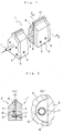
- the supply nozzle 1 includes a nozzle body 2 comprising a longer nozzle half 3 on a front side and a nozzle half 4 on a back side, which are integrally coupled to each other by a bolt 5.
- a side enclosure 6 is secured by bolts 7 to each of the front-side nozzle half 3 and the back-side nozzle half 4 coupled to each other.
- a joint surface of the front-side nozzle half 3 is formed into a flat shape, and a coating material reservoir 8 semicircular in section is defined in a joint surface of the back-side nozzle half 4 at a location intermediate in a direction of the height thereof to extend in a lengthwise direction.
- the back-side nozzle half 4 is formed, so that the thickness (lateral distance) of an upper portion above the coating material reservoir 8 is slightly smaller than the thickness of a lower portion below the coating material reservoir 8.
- a slight gap is provided between the upper portion of the back-side nozzle half 4 and the joint surface of the front-side nozzle half 3.
- a longitudinally extending nozzle passage 9 is defined by the gap between the joint surface of the front-side nozzle half 3 and the upper portion of the back-side nozzle half 4 above the coating material reservoir 8, so that its lower end communicates with the coating material reservoir 8, and its upper end opens to the outside.
- the upper end of the nozzle passage 9 is an elongated nozzle port 10 which opens into an upper surface of the nozzle body 2.
- a coating material feed pipe 11 for feeding a coating material is mounted in the nozzle body 2 to extend over the entire length of the coating material reservoir 8. More specifically, the coating material feed pipe 11 is mounted, so that it extends through one of the side enclosures 6 and through a substantially central portion of the coating material reservoir 8 to reach the other side enclosure 6, as shown in Fig.3. Further, at least one coating material feed bore 12 is provided in the coating material feed pipe 11 for guiding the coating material in the coating material feed pipe 11 into the coating material reservoir 8 uniformly in a lengthwise direction. In the embodiment shown in Fig.3, the one coating material feed bore 12 is provided in the coating material feed pipe 11 at a lengthwise center of the coating material reservoir 8.
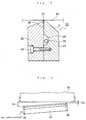
- the coating material feed bore 12 opens into the coating material feed pipe 11 at such a circumferential location that an ink fed does not flow directly into the nozzle passage 9, as shown in Fig.2.
- the thickness of ink coated can be uniformized.
- a coating material flow path defined between the coating material feed pipe 11 and the coating material reservoir can exhibit a flow rate uniformizing effect by changing the direction of flowing of the coating material and varying the sectional area, thereby effectively conducting the uniformization of the coating material.
- the coating material feed bore 12 opens at a location where it faces to a deepest portion of a recessed side of the coating material reservoir 8.
- the number of the coating material feed bores 12 provided in the coating material feed pipe 11 may be two or more, as shown in Fig.4, or the sectional shapes of the coating material feed bore 12 and the coating material feed pipe 11 may be changed, or a plurality of the coating material feed pipes 11 may be placed in parallel to one another, depending on coating conditions such as the nature of the coating material, e.g., the viscosity, the amount of coating material fed, the length of the nozzle port 10 and the like.
- the nozzle port 10 in the coating material supply nozzle 1 is placed in parallel to a continuous substrate 14 traveling through guide rolls 13, 13, and a gap G between the substrate 14 and the nozzle port 10 is provided uniformly over the entire length of the coating material supply nozzle 1, as shown in Figs.5 and 6.
- the substrate 14 is allowed to travel at a predetermined speed and at the same time, a predetermined amount of the coating material is fed into the coating material feed pipe 11 from a lengthwise end with respect of the coating material supply nozzle 1.
- the coating material in the coating material feed pipe 11 is fed into the coating material reservoir 8 through the coating material feed bore 12 disposed at the lengthwise center of the coating material reservoir 8, and the flow rate of the coating material is adjusted uniformly in the lengthwise direction of the coating material reservoir 8.
- the coating material feed bore 12 opens into the coating material feed pipe 11 at the location where it faces to the deepest portion of the recessed side of the coating material reservoir 8 and hence, while the coating material is passed through a flow path defined between an outer peripheral surface of the coating material feed pipe 11 and an inner peripheral surface of the coating material reservoir 8, i.e., a flow path where the direction of flowing of the coating material is changed and the sectional area is changed, the coating material is subjected to a change in flow course and to an increase and decrease in volume, and it then reaches the nozzle passage 9.
- the coating material While the coating material is passed through the nozzle passage 9, it is subjected to the uniformization of flow rate attributable to the above-described flow path, whereby the flow rate in the lengthwise direction of the coating material reservoir 8 is uniformized. In this manner, the coating material is passed through the nozzle passage 9 and discharged from the nozzle port 10 uniformly over the entire length thereof, and thus applied uniformly to the substrate 14.
- the state of feeding of the coating material can be changed regulated without changing of the construction other that the construction of the coating material feed pipe 11 in the coating material supply nozzle 1.
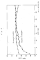
- Fig.7 shows the thicknesses of coating materials coated to the substrates 14 and 30 by the coating material supply nozzle 1 according to the embodiment shown in Fig.1 and the coating material supply nozzles 20 of the prior art examples 1 and 2 shown in Figs.12 and 14 for comparison with each other.
- the coating materials were fed and coated leftwards from the right side in Fig.7 under coating conditions which will be described below.
- the inside diameter of the coating material feed pipe 11 which was a component for only the coating material supply nozzle 1 was 10 mm; the coating material feed bore 12 was of an elliptic shape having a width of 6 mm and a length of 15 mm; the nozzle ports 10 and 27 which were other supply components for the nozzle 1 and the size of the prior art nozzles was set at a length of 35 mm and a width of 190 ⁇ m; the gap G was set such that (G1 + G2)/2 was 200 ⁇ m; and the viscosity of the coating material was set at 2,400 mPa•S.
- the supply nozzle according to the present invention is of a structure in which the coating material is fed from the coating material feed bore 12 disposed in the coating material feed pipe 11 at the lengthwise center of the coating material reservoir 8 and hence, a variation in thickness of the applied coating material was suppressed to the order of 2.5 ⁇ m at the maximum over the entire length of the nozzle port 10 and thus, the uniform coating was achieved.
- the supply nozzle is of a structure in which the coating material is supplied from a coating material feed bore 29 disposed at a lengthwise end of a coating material reservoir 25.
- the supply nozzle is of a structure in which the coating material is supplied through a coating material feed bore 29a into a coating material reservoir 25 at a lengthwise central position from a direction perpendicular to the lengthwise direction of the coating material reservoir 25.
- Fig.8 shows the thicknesses of coating materials coated to the substrates under coating conditions similar to those shown in Fig.7, except that the size of the nozzle ports 10 and 27 as supply components of the nozzles according to the present invention and in the prior art example 1 was set at a length of 35 mm and a width of 590 ⁇ m; the gap G was set such that (G1 + G2)/2 was 400 ⁇ m; and the viscosity of the coating material was set at 4,000 mPa•S.
- Fig.8 shows the thicknesses of coating materials coated to the substrates under coating conditions similar to those shown in Fig.7, except that the size of the nozzle ports 10 and 27 as supply components of the nozzles according to the present invention and in the prior art example 1 was set at a length of 35 mm and a width of 590 ⁇ m; the gap G was set such that (G1 + G2)/2 was 400 ⁇ m; and the viscosity of the coating material was set at 4,000 mPa•S.
- Fig.9 shows the thicknesses of coating materials coated to the substrates under coating conditions similar to those shown in Fig.7, except that the size of the nozzle ports 10 and 27 as supply components of the nozzles according to the present invention and in the prior art example 1 was set at a length of 35 mm and a width of 190 ⁇ m; the gap G was set such that (G1 + G2)/2 was 100 ⁇ m; and the viscosity of the coating material was set at 980 mPa•S.
- a variation in thickness of the applied coating material was suppressed to the order of 1.0 ⁇ m at the maximum over the entire length of the nozzle port 10 and hence, the uniform coating was achieved, as in Fig.7.
- the thickness of the applied coating material was larger at the inlet side and smaller at the leading end, and a variation in thickness amounted to 3 ⁇ m at the maximum and hence, the uniform coating was not realized.
- Fig.10 shows the thickness in the example of the present invention shown in Fig.7 (shown by a black rhombic shape) and the thickness in an example of the present invention in which the coating material feed bore 12 was of an elliptic shape with a width of 6 mm and length of 30 mm (shown by a black quadrilateral shape).
- the uniform coating was achieved over the entire length of the nozzle port 10. It was also found that when the length of the coating material feed bore 12 is larger, the uniformity tends to be higher.
- Fig.11 shows the thickness in the example of the present invention shown in Fig.7 (shown by a black rhombic shape) and the thickness in an example of the present invention in which the two coating material feed bores 12 having the same size as in Fig.7 are provided at locations spaced laterally apart from the center of the coating material reservoir 8 (shown by a black quadrilateral shape).
- the uniform coating was achieved over the entire length of the nozzle port 10. It was also found that when the two coating material feed bores 12 are provided, the uniformity tends to be higher.
- the coating material can be supplied from the lengthwise end to the coating material supply nozzle 1 by the coating material feed pipe 11 and moreover, the coating material in the coating material feed pipe 11 can be guided from the coating material feed bore 12 into the coating material reservoir 8 uniformly in the lengthwise direction of the coating material reservoir 8. This ensures that the coating material can be discharged uniformly over the entire length of the nozzle port 10 and applied uniformly to the substrate 14.
- the coating material supply nozzle provides the following effects:
- the coating material can be supplied to the coating material supply nozzle from the lengthwise end and moreover, can be discharged uniformly over the entire length of the nozzle port and applied uniformly onto the substrate. Further, the state of supplying of the coating material can be changed and regulated easily.
Landscapes
- Coating Apparatus (AREA)
- Nozzles (AREA)
- Application Of Or Painting With Fluid Materials (AREA)
Applications Claiming Priority (2)
| Application Number | Priority Date | Filing Date | Title |
|---|---|---|---|
| JP2001387986A JP2003181355A (ja) | 2001-12-20 | 2001-12-20 | 塗工剤供給ノズル |
| JP2001387986 | 2001-12-20 |
Publications (2)
| Publication Number | Publication Date |
|---|---|
| EP1321194A2 true EP1321194A2 (de) | 2003-06-25 |
| EP1321194A3 EP1321194A3 (de) | 2004-10-20 |
Family
ID=19188109
Family Applications (1)
| Application Number | Title | Priority Date | Filing Date |
|---|---|---|---|
| EP02258779A Withdrawn EP1321194A3 (de) | 2001-12-20 | 2002-12-19 | Düse für Beschichtungsmaterial |
Country Status (5)
| Country | Link |
|---|---|
| US (1) | US20030197076A1 (de) |
| EP (1) | EP1321194A3 (de) |
| JP (1) | JP2003181355A (de) |
| KR (1) | KR20030052232A (de) |
| TW (1) | TW527222B (de) |
Cited By (1)
| Publication number | Priority date | Publication date | Assignee | Title |
|---|---|---|---|---|
| WO2003078510A1 (de) * | 2002-03-15 | 2003-09-25 | P-D Tec Fil Gmbh Technische Filamente | Verfahren zur erzeugung von hochbelastbaren fadenprepregs |
Families Citing this family (4)
| Publication number | Priority date | Publication date | Assignee | Title |
|---|---|---|---|---|
| JP3957640B2 (ja) * | 2002-02-21 | 2007-08-15 | アイシン化工株式会社 | 幅広スリットノズル及び幅広スリットノズルによる塗装方法 |
| KR200451810Y1 (ko) * | 2008-04-21 | 2011-01-13 | 김태호 | 오프너 |
| US10493527B1 (en) | 2018-05-08 | 2019-12-03 | General Electric Company | System for additive manufacturing |
| CN218945476U (zh) * | 2022-11-29 | 2023-05-02 | 宁德时代新能源科技股份有限公司 | 涂布模头和涂布设备 |
Citations (1)
| Publication number | Priority date | Publication date | Assignee | Title |
|---|---|---|---|---|
| US5993553A (en) | 1996-07-30 | 1999-11-30 | Kolon Industries, Inc. | Extrusion coating apparatus |
Family Cites Families (6)
| Publication number | Priority date | Publication date | Assignee | Title |
|---|---|---|---|---|
| US1751960A (en) * | 1928-05-10 | 1930-03-25 | Veenstra Benjamin | Water-flow device |
| US2215176A (en) * | 1940-03-02 | 1940-09-17 | Percy M Forster | Burner head |
| US3479989A (en) * | 1967-11-28 | 1969-11-25 | Eastman Kodak Co | Extrusion coating apparatus |
| DE2238133B2 (de) * | 1972-08-03 | 1976-11-11 | Agfa-Gevaert Ag, 5090 Leverkusen | Kaskadengiesser |
| JPH0871480A (ja) * | 1994-08-31 | 1996-03-19 | Sony Corp | 塗布装置 |
| US5967425A (en) * | 1997-09-22 | 1999-10-19 | Wang; Shoei-Yuan | Air blast apparatus for yarn drawing machines |
-
2001
- 2001-12-20 JP JP2001387986A patent/JP2003181355A/ja active Pending
-
2002
- 2002-06-12 KR KR1020020032813A patent/KR20030052232A/ko not_active Withdrawn
- 2002-06-19 TW TW091113329A patent/TW527222B/zh not_active IP Right Cessation
- 2002-12-17 US US10/321,168 patent/US20030197076A1/en not_active Abandoned
- 2002-12-19 EP EP02258779A patent/EP1321194A3/de not_active Withdrawn
Patent Citations (1)
| Publication number | Priority date | Publication date | Assignee | Title |
|---|---|---|---|---|
| US5993553A (en) | 1996-07-30 | 1999-11-30 | Kolon Industries, Inc. | Extrusion coating apparatus |
Cited By (1)
| Publication number | Priority date | Publication date | Assignee | Title |
|---|---|---|---|---|
| WO2003078510A1 (de) * | 2002-03-15 | 2003-09-25 | P-D Tec Fil Gmbh Technische Filamente | Verfahren zur erzeugung von hochbelastbaren fadenprepregs |
Also Published As
| Publication number | Publication date |
|---|---|
| TW527222B (en) | 2003-04-11 |
| EP1321194A3 (de) | 2004-10-20 |
| US20030197076A1 (en) | 2003-10-23 |
| KR20030052232A (ko) | 2003-06-26 |
| JP2003181355A (ja) | 2003-07-02 |
Similar Documents
| Publication | Publication Date | Title |
|---|---|---|
| US4142010A (en) | Method for applying a viscous fluid to a substrate | |
| US9855583B2 (en) | Method for dispensing controlled patterns of liquid material | |
| US7578882B2 (en) | Module, nozzle and method for dispensing controlled patterns of liquid material | |
| JP3220265B2 (ja) | 塗工装置 | |
| JP4331687B2 (ja) | ノズル配列構造 | |
| EP1321194A2 (de) | Düse für Beschichtungsmaterial | |
| KR101737683B1 (ko) | 다이 코터용 유량조절부재 및 이를 포함하는 코팅 장치 | |
| JPH07256182A (ja) | ウェブ用塗布装置 | |
| US6746537B2 (en) | Coating apparatus | |
| KR20190019054A (ko) | 도포기 및 도포 장치 | |
| CN118527310B (zh) | 一种双面同步涂布点胶设备 | |
| CN1330430C (zh) | 用于在基板上分配可流动材料的接触型模具及其方法 | |
| JP3615637B2 (ja) | 塗布装置 | |
| EP0569303B1 (de) | Flüssigkeitsverteiler in dem Ströme zusammenstossen | |
| JPH1119564A (ja) | 塗工装置 | |
| JP4354598B2 (ja) | 両面塗工型塗工装置 | |
| JPH07185434A (ja) | 塗布装置 | |
| JP4174861B2 (ja) | ダイレクトファウンテンコーター | |
| CN223010838U (zh) | 一种围帘式气浴机构及围帘式气浴装置 | |
| JP2006181448A (ja) | ダイヘッド | |
| JP2757452B2 (ja) | 2液同時塗工装置 | |
| JPH077771U (ja) | 塗布用ノズルチップ | |
| JP2001232266A (ja) | 塗布ヘッド | |
| JPH07195017A (ja) | ブレードコータ | |
| JP4103598B2 (ja) | 塗布工具および塗布装置 |
Legal Events
| Date | Code | Title | Description |
|---|---|---|---|
| PUAI | Public reference made under article 153(3) epc to a published international application that has entered the european phase |
Free format text: ORIGINAL CODE: 0009012 |
|
| AK | Designated contracting states |
Designated state(s): AT BE BG CH CY CZ DE DK EE ES FI FR GB GR IE IT LI LU MC NL PT SE SI SK TR |
|
| AX | Request for extension of the european patent |
Extension state: AL LT LV MK RO |
|
| PUAL | Search report despatched |
Free format text: ORIGINAL CODE: 0009013 |
|
| AK | Designated contracting states |
Kind code of ref document: A3 Designated state(s): AT BE BG CH CY CZ DE DK EE ES FI FR GB GR IE IT LI LU MC NL PT SE SI SK TR |
|
| AX | Request for extension of the european patent |
Extension state: AL LT LV MK RO |
|
| 17P | Request for examination filed |
Effective date: 20050419 |
|
| AKX | Designation fees paid |
Designated state(s): AT BE BG CH CY CZ DE DK EE ES FI FR GB GR IE IT LI LU MC NL PT SE SI SK TR |
|
| STAA | Information on the status of an ep patent application or granted ep patent |
Free format text: STATUS: THE APPLICATION IS DEEMED TO BE WITHDRAWN |
|
| 18D | Application deemed to be withdrawn |
Effective date: 20100729 |