EP1321246A2 - Outil à main motorisé fonctionnel - Google Patents
Outil à main motorisé fonctionnel Download PDFInfo
- Publication number
- EP1321246A2 EP1321246A2 EP02080449A EP02080449A EP1321246A2 EP 1321246 A2 EP1321246 A2 EP 1321246A2 EP 02080449 A EP02080449 A EP 02080449A EP 02080449 A EP02080449 A EP 02080449A EP 1321246 A2 EP1321246 A2 EP 1321246A2
- Authority
- EP
- European Patent Office
- Prior art keywords
- power tool
- grip
- hand
- held power
- tool according
- Prior art date
- Legal status (The legal status is an assumption and is not a legal conclusion. Google has not performed a legal analysis and makes no representation as to the accuracy of the status listed.)
- Withdrawn
Links
Images

Classifications
-
- B—PERFORMING OPERATIONS; TRANSPORTING
- B25—HAND TOOLS; PORTABLE POWER-DRIVEN TOOLS; MANIPULATORS
- B25F—COMBINATION OR MULTI-PURPOSE TOOLS NOT OTHERWISE PROVIDED FOR; DETAILS OR COMPONENTS OF PORTABLE POWER-DRIVEN TOOLS NOT PARTICULARLY RELATED TO THE OPERATIONS PERFORMED AND NOT OTHERWISE PROVIDED FOR
- B25F5/00—Details or components of portable power-driven tools not particularly related to the operations performed and not otherwise provided for
- B25F5/02—Construction of casings, bodies or handles
Definitions
- the present invention relates to a hand held power tool with an improved functionality.
- the invention relates to an electrically driven power tool, such as an electric drill, screwdriver or a circular saw.
- these machines generally comprise a main body, inside which there is an electric motor which drives the rotation of a chuck, on which a specific work tool is assembled.
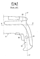
- the hand held power tool comprises, in particular, a grip 10, arranged in a substantially perpendicular direction to the longitudinal axis X of the main body 11 of the machine (which in the specific case illustrated in figure 1, coincides with the rotation axis of the tool-holder chuck).
- a start and drive switch which is activated by means of a push-button 18 protruding from the external profile of the grip, which can move in a substantially perpendicular direction to the axis Y' of figure 1.
- the accumulation of biomechanical stress can take place on the hand and arm, with a consequent increase in the risk of the onset of muscular-skeletal traumas, such as tendinitis, carpal tunnel syndrome, Raynaud syndrome, muscular pain, tenosynivitis or epicondylitis.
- An objective of the present invention is therefore to eliminate the technical drawbacks reported and, in particular, to produce a hand held power tool with an improved functionality, which allows the user to apply human strength more efficiently, whatever type of grip is adopted.
- Another objective of the present invention is to indicate a hand held power tool with an improved functionality, which allows the user to maintain, during use, a so-called “neutral posture" of the hand and forearm, known to ergonomists as being the most advantageous in terms of comfort and prevention of a series of pathologies connected with the use of power tools.
- An additional objective of the invention is to produce a hand held power tool with an improved functionality, which maintains safety and reliability characteristics, with respect to hand held power tools of the traditional type, without jeopardizing encumbrance, which remains equivalent to that of traditional machines.
- the hand held power tool according to the invention can be advantageously distinguished by the particular configuration of the grip and accessories relating thereto, so as to allow much a more comfortable and less tiring use, with a consequent increase in work productivity and efficiency, with a drastic reduction in fatigue on the part of the user.
- the "neutral posture" of the hand and forearm is obtained, in particular, when the fingers are slightly bent on the three articulations (with a bending degree which gradually increases from the index finger to the little finger), the thumb is in semi-opposition with respect to the other fingers and the wrist of the forearm is slightly stretched with a mild inclination of the ulna.
- 11 indicates a main body of a hand held power tool, in particular a power tool, inside which the electric activation motor 13 of the tool, the motor commutator, generally indicated with 14, and the relative coiling 15, are mainly housed.
- the power tool consists of an electric drill or a screwdriver drill or pneumatic drill or hammer
- the power tool on the external surface above the main body 11 of the drill, there is a longitudinal groove 20, which facilitates a firmer and safer hold of the power tool.
- This kind of hold particularly preferred by experts in the field as it enables a force to be applied in a direction which is parallel to the rotation axis of the motor allowing a reduction in the torque during use, consists of the possibility of inserting the index finger 21 of the hand 22 into the groove 20 and the mid-finger 26 in a parallel position, resting the thumb 23, in semi-opposition, in correspondence with the upper portion of the body 11 (see, in particular, figure 4 for a rapid verification), so as to exert greater force on the tool and have a better control of the machine, with respect to a conventional hold, of the "pistol" type (schematically illustrated in figure 3).
- the hand held power tool also comprises a grip 16, which, according to the invention, has a particular configuration, suitable for maintaining optimum ergonomic conditions for the user, and which internally houses a main body of the start and/or drive switch, indicated with 17, activated by the pressure of a push-button 18, which protrudes from the profile of the grip 16 (towards the inside of the machine), making it accessible to the user's hand.
- a grip 16 which, according to the invention, has a particular configuration, suitable for maintaining optimum ergonomic conditions for the user, and which internally houses a main body of the start and/or drive switch, indicated with 17, activated by the pressure of a push-button 18, which protrudes from the profile of the grip 16 (towards the inside of the machine), making it accessible to the user's hand.
- Some power tools also have a stop device, generally indicated with 19 in figure 1, which allows the push-button 18 to be kept in position without having to maintain the constant pressure of the fingers.
- a suitable angle of the grip 16 is created, with respect to the main body 11, to favour a correct positioning of the hand and forearm of the user during use.
- the hand held power tool, object of the present invention has a grip 16 having an median axis Y inclined, with respect to the longitudinal axis X of the body 11, at an obtuse angle ⁇ , substantially corresponding to the angle formed by the hand with the forearm in the so-called "neutral posture", known to ergonomists as being the most advantageous in terms of comfort and prevention of a series of pathologies associated with the use of power tools.
- This configuration provides an extremely convenient, comfortable, safe and efficient grip of the hand held power tool during work execution; in particular, the structural conformation of the grip 16 allows a force to be exerted, which is regularly distributed between the various muscles of the human body, and also allows minimum stress, with respect to that exerted on power tool grips of the traditional type.
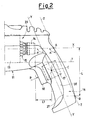
- Figure 2 illustrates in detail the construction of the angle ⁇ ; in this specific case, the inclination of the median axis Y of the grip 16, with respect to the longitudinal axis X of the body 11, is obtained by constructing a parallel to the line Z passing through points A (intersection point between the external profile of the grip 16 and longitudinal axis X) and B (point lying on the external profile of the grip 16, which is at a distance L, equal to at least 100 mm, from the longitudinal axis X).
- the particular inclination of the grip 16 forms an additional advantageous characteristic of the hand held power tool according to the invention.
- This inclined configuration in fact, allows the push-button 18 of the switch 17 to move in a direction (indicated by the arrow P of figure 2) which is substantially perpendicular to the median axis Y of the grip 16; this enables the user to maneuver the activation button 18 with much less force than is necessary with drive push-buttons of the traditional type, which are compelled to move in a substantially parallel direction to the axis X (see figure 1 for a rapid comparison).
- the distance, indicated with L1 in figure 2 between the terminal surface of the commutator 14 of the electric motor 13 and the geometric centre C of the main body of the switch 17 is less than a pre-fixed size which, in illustrative and preferred but non-limiting embodiments of the present invention, is 70 mm.
- Figures 3 and 4 specifically show the activation direction of the push-button of the switch and inclination of the grip 16; these figures also clearly illustrate how force and energy are applied by the human body to the power tool as efficiently as possible, as the application direction of said force is always parallel to the longitudinal axis X (corresponding to the rotation axis of the motor 13), both in the "pistol” type of grip (figure 3, in which the force application direction is indicated by the line R), and in the "upper” type of grip, with two fingers, preferred by experts (figure 4, in which the force application direction is indicated by the line S).
- the push-button 18 is situated in the upper part of the grip 16, so that the line T (see figure 2), which extends to the lower part of the motor 13, crosses the main body of the switch 17.
- This particular arrangement of the switch 17 also avoids jeopardizing the encumbrance, which is comparable to that of power tools of the traditional type, at the same time maintaining an adequate inclination of the grip 16, in order to obtain the advantages of comfort and reduction in fatigue of the operator during use, as mentioned above.
- the arrangement of the components present inside the hand held power tool is also designed in such a way as to avoid encumbrance of the power tool, above all in correspondence with the interface existing between the main body 11 and grip 16; compactness and reduction in encumbrance are, in fact, among the prerogatives most widely requested by the market.
- the grip 16 has, in its lower part, an enlarged terminal section 27, which is specifically shaped for blocking the hand holding the power tool in position (in the case of a "pistol” hold), thus allowing an even firmer and safer grip.
- the inclined conformation of the grip 16 combined with its particular dimensions, surface geometry and transversal sections, allows a uniform distribution of the surface pressure on a wide area of the hand during the use of the hand held power tool.
- the machine according to the invention is consequently comfortable for the user and allows an adequate force to be applied, maintaining constant control of the tool; in addition, the conformation of the grip, as already mentioned, prevents the onset of traumas of the muscular-skeletal type.
- the diameter of the grip 16 is also optimized so as to ensure a uniform contribution of all fingers to the safety of the hold; the correct size of said diameter is obtained from experimental studies and biomechanical force measurements applied by the fingers and relative moments and is a compromise between an excessive bending angle of the five fingers in holding position (reduced diameter) and a non-adequate use of all fingers for their complete adhesion to the grip (due to an excessively large diameter).
- a grip 16 has been projected with an elliptical section, having a longitudinal line 28 on both opposite external surfaces; this line 28 is sufficiently prominent as to be instantly perceived upon touch, even in the present of work-gloves, to ensure a completely tridimensional perception on the part of the operator of the position of his hand on the grip 16, thus increasing accuracy of use of the hand held power tool, above all if used for precision works.
- the surface of the grip must not be too smooth, allowing a symptomatic tactile contact and contributing to attenuating the vibrations transmitted by the machine to the hand and forearm.
Landscapes
- Engineering & Computer Science (AREA)
- Mechanical Engineering (AREA)
- Portable Power Tools In General (AREA)
- Harvester Elements (AREA)
- Perforating, Stamping-Out Or Severing By Means Other Than Cutting (AREA)
Applications Claiming Priority (2)
| Application Number | Priority Date | Filing Date | Title |
|---|---|---|---|
| ITVI20010264 | 2001-12-21 | ||
| IT2001VI000264A ITVI20010264A1 (it) | 2001-12-21 | 2001-12-21 | Macchina utensile a funzionalita' migliorata |
Publications (2)
| Publication Number | Publication Date |
|---|---|
| EP1321246A2 true EP1321246A2 (fr) | 2003-06-25 |
| EP1321246A3 EP1321246A3 (fr) | 2004-06-16 |
Family
ID=11461725
Family Applications (1)
| Application Number | Title | Priority Date | Filing Date |
|---|---|---|---|
| EP02080449A Withdrawn EP1321246A3 (fr) | 2001-12-21 | 2002-12-17 | Outil à main motorisé fonctionnel |
Country Status (3)
| Country | Link |
|---|---|
| US (1) | US20030146008A1 (fr) |
| EP (1) | EP1321246A3 (fr) |
| IT (1) | ITVI20010264A1 (fr) |
Cited By (7)
| Publication number | Priority date | Publication date | Assignee | Title |
|---|---|---|---|---|
| GB2396577A (en) * | 2002-12-23 | 2004-06-30 | Milwaukee Electric Tool Corp | Trigger assembly for a power tool |
| JP2008284617A (ja) * | 2007-05-15 | 2008-11-27 | Makita Corp | 可搬型動力工具 |
| JP2009248222A (ja) * | 2008-04-03 | 2009-10-29 | Makita Corp | 可搬型動力工具 |
| EP2147754A4 (fr) * | 2007-05-15 | 2010-11-03 | Makita Corp | Outil électrique portatif |
| EP2364818A1 (fr) * | 2010-03-08 | 2011-09-14 | HILTI Aktiengesellschaft | Machine-outil manuelle |
| USD646947S1 (en) | 2010-08-13 | 2011-10-18 | Black & Decker Inc. | Drill |
| US12233523B2 (en) | 2020-12-07 | 2025-02-25 | Black & Decker Inc. | Power tool with multiple modes of operation and ergonomic handgrip |
Families Citing this family (25)
| Publication number | Priority date | Publication date | Assignee | Title |
|---|---|---|---|---|
| USD526178S1 (en) * | 2003-01-24 | 2006-08-08 | Robert Bosch Gmbh | Electric drill |
| USD538126S1 (en) * | 2003-08-29 | 2007-03-13 | Robert Bosch Gmbh | Hammer drill with work piece holder |
| AU155884S (en) * | 2003-08-29 | 2004-07-14 | Bosch Gmbh Robert | Impact drilling machine |
| CA106161S (en) | 2003-09-10 | 2005-06-09 | Chervon Internat Trading Co Ltd | Drill |
| USD502376S1 (en) * | 2003-09-29 | 2005-03-01 | Positec Power Tools (Suzhou) Co., Limited | Impact drill |
| CA108959S (en) * | 2004-05-13 | 2005-12-02 | Nanjing Chervon Ind Co Ltd | Drill |
| JP4456499B2 (ja) * | 2005-02-10 | 2010-04-28 | 株式会社マキタ | 作業工具 |
| CA113638S (en) * | 2005-06-17 | 2007-03-30 | Nanjing Chervon Ind Co Ltd | Electric drill |
| USD533420S1 (en) * | 2005-11-03 | 2006-12-12 | Gmca Pty Limited | Power tool drill |
| US20070221391A1 (en) * | 2006-03-27 | 2007-09-27 | Pospisil Kenneth G | Apparatus, accessories and/or controls attached to a drill of any sort for screwing, impacting and/or drilling into anything; including different position's and controls for grasping or positioning a drill of any sort to function |
| JP5467757B2 (ja) * | 2008-11-14 | 2014-04-09 | 株式会社マキタ | 作業工具 |
| USD609544S1 (en) | 2009-02-24 | 2010-02-09 | Black & Decker, Inc. | Drill driver |
| USD617622S1 (en) | 2009-09-30 | 2010-06-15 | Black & Decker Inc. | Impact driver |
| USD626394S1 (en) | 2010-02-04 | 2010-11-02 | Black & Decker Inc. | Drill |
| WO2013032374A1 (fr) * | 2011-08-26 | 2013-03-07 | Husqvarna Ab | Ensemble guide et commande |
| DE202013103023U1 (de) * | 2012-07-14 | 2013-10-04 | Hitachi Koki Co., Ltd. | Elektrowerkzeug |
| DE102013207689A1 (de) * | 2013-04-26 | 2014-10-30 | Robert Bosch Gmbh | Handwerkzeugmaschine |
| JP6085225B2 (ja) | 2013-06-27 | 2017-02-22 | 株式会社マキタ | ネジ締め電動工具 |
| US9559628B2 (en) | 2013-10-25 | 2017-01-31 | Black & Decker Inc. | Handheld power tool with compact AC switch |
| US20150151424A1 (en) * | 2013-10-29 | 2015-06-04 | Black & Decker Inc. | Power tool with ergonomic handgrip |
| JP6246649B2 (ja) * | 2014-04-10 | 2017-12-13 | 株式会社マキタ | 電動工具 |
| EP3566176B1 (fr) * | 2017-01-04 | 2025-10-29 | Interlink Electronics, Inc. | Détection multimodale pour interface utilisateur d'outil électrique |
| US11498198B2 (en) * | 2019-08-20 | 2022-11-15 | The Boeing Company | Ergonomic handle for a power tool |
| US20220009072A1 (en) * | 2020-07-09 | 2022-01-13 | Snap-On Incorporated | Ergonomic housing for a power tool |
| TWM635552U (zh) * | 2022-01-11 | 2022-12-21 | 鑽全實業股份有限公司 | 研磨工具及其機殼 |
Family Cites Families (10)
| Publication number | Priority date | Publication date | Assignee | Title |
|---|---|---|---|---|
| US4330093A (en) * | 1980-08-08 | 1982-05-18 | Western Electric Company, Inc. | Thumb-controlled hand-held tool |
| US4448098A (en) * | 1982-03-10 | 1984-05-15 | Katsuyuki Totsu | Electrically driven screw-driver |
| US4759240A (en) * | 1987-04-28 | 1988-07-26 | Samson Lin | Electric screwdriver with adjustable joint |
| US4962681A (en) * | 1988-11-09 | 1990-10-16 | Yang Tai Her | Modular manual electric appliance |
| DE19605202C1 (de) * | 1996-02-13 | 1997-09-18 | Atlas Copco Elektrowerkzeuge | Elektrowerkzeugmaschine mit Umschalteinrichtung für Rechts-/Linkslauf |
| US6102134A (en) * | 1998-10-16 | 2000-08-15 | Black & Decker Inc. | Two-position screwdriver |
| USD462593S1 (en) * | 2001-06-18 | 2002-09-10 | Toolovation, Llc | Battery powered screwdriver |
| US6364033B1 (en) * | 2001-08-27 | 2002-04-02 | Techtronic Industries Co. Ltd. | Portable electric tool |
| US6688407B2 (en) * | 2001-10-10 | 2004-02-10 | Porter-Cable/Delta | Belt clip for hand-held power tools |
| US7143841B2 (en) * | 2001-10-10 | 2006-12-05 | Black & Decker Inc. | Belt clip for hand-held power tools |
-
2001
- 2001-12-21 IT IT2001VI000264A patent/ITVI20010264A1/it unknown
-
2002
- 2002-12-17 EP EP02080449A patent/EP1321246A3/fr not_active Withdrawn
- 2002-12-20 US US10/326,902 patent/US20030146008A1/en not_active Abandoned
Cited By (13)
| Publication number | Priority date | Publication date | Assignee | Title |
|---|---|---|---|---|
| GB2396577A (en) * | 2002-12-23 | 2004-06-30 | Milwaukee Electric Tool Corp | Trigger assembly for a power tool |
| US7015409B2 (en) | 2002-12-23 | 2006-03-21 | Milwaukee Electric Tool Corporation | Power tool trigger |
| GB2396577B (en) * | 2002-12-23 | 2006-07-19 | Milwaukee Electric Tool Corp | Power tool trigger |
| US8657029B2 (en) | 2007-05-15 | 2014-02-25 | Makita Corporation | Portable power tool with grooved hand grip |
| EP2147754A4 (fr) * | 2007-05-15 | 2010-11-03 | Makita Corp | Outil électrique portatif |
| US8261852B2 (en) | 2007-05-15 | 2012-09-11 | Makita Corporation | Portable power tool |
| JP2008284617A (ja) * | 2007-05-15 | 2008-11-27 | Makita Corp | 可搬型動力工具 |
| EP2647474A3 (fr) * | 2007-05-15 | 2016-04-06 | Makita Corporation | Outil électrique portable |
| US9550290B2 (en) | 2007-05-15 | 2017-01-24 | Makita Corporation | Portable power tool with improved grip portion |
| JP2009248222A (ja) * | 2008-04-03 | 2009-10-29 | Makita Corp | 可搬型動力工具 |
| EP2364818A1 (fr) * | 2010-03-08 | 2011-09-14 | HILTI Aktiengesellschaft | Machine-outil manuelle |
| USD646947S1 (en) | 2010-08-13 | 2011-10-18 | Black & Decker Inc. | Drill |
| US12233523B2 (en) | 2020-12-07 | 2025-02-25 | Black & Decker Inc. | Power tool with multiple modes of operation and ergonomic handgrip |
Also Published As
| Publication number | Publication date |
|---|---|
| EP1321246A3 (fr) | 2004-06-16 |
| US20030146008A1 (en) | 2003-08-07 |
| ITVI20010264A1 (it) | 2003-06-21 |
Similar Documents
| Publication | Publication Date | Title |
|---|---|---|
| EP1321246A2 (fr) | Outil à main motorisé fonctionnel | |
| US4934222A (en) | Ergonomic tool | |
| EP2221150B1 (fr) | Poignée ergonomique pour outil électrique | |
| RU2446029C2 (ru) | Ручной инструмент (варианты) и ручка для ручного инструмента | |
| US8261853B2 (en) | Ergonomic handle for a power tool | |
| HK1257526A1 (zh) | 辅助动力工具把手 | |
| US5275068A (en) | Handle assembly for relieving wrist joint stress | |
| US20050247466A1 (en) | Power tool with adjustable hand grip | |
| US5311949A (en) | Power screwdriver handle configuration | |
| WO1996005013A1 (fr) | Poignee de perceuse de conception ergonomique dotee d'un support pour avant-bras | |
| JP2003080473A (ja) | 手工具の制御装置 | |
| JP5201389B2 (ja) | 携帯用電気のこぎり | |
| JP2010184304A5 (fr) | ||
| AU6638996A (en) | Ergonomic handle for terminal insertion tool | |
| WO1999030874A1 (fr) | Poignee a profil concave/convexe | |
| JP2006015480A (ja) | 電動工具 | |
| KR940005944B1 (ko) | 인간공학적 수공구 | |
| CN215241007U (zh) | 一种握刀矫正器 | |
| US10562169B2 (en) | Hand-guided machine tool with ergonomic grip part | |
| JP2001517560A (ja) | 手持工具機械 | |
| US6321417B1 (en) | Ergonomical tool handle | |
| KR860001081B1 (ko) | 수동 공구용 손잡이 | |
| CN220481621U (zh) | 电动工具 | |
| CN101888919A (zh) | 把手 | |
| CLAMPS et al. | PRICING! |
Legal Events
| Date | Code | Title | Description |
|---|---|---|---|
| PUAI | Public reference made under article 153(3) epc to a published international application that has entered the european phase |
Free format text: ORIGINAL CODE: 0009012 |
|
| AK | Designated contracting states |
Designated state(s): AT BE BG CH CY CZ DE DK EE ES FI FR GB GR IE IT LI LU MC NL PT SE SI SK TR |
|
| AX | Request for extension of the european patent |
Extension state: AL LT LV MK RO |
|
| PUAL | Search report despatched |
Free format text: ORIGINAL CODE: 0009013 |
|
| AK | Designated contracting states |
Kind code of ref document: A3 Designated state(s): AT BE BG CH CY CZ DE DK EE ES FI FR GB GR IE IT LI LU MC NL PT SE SI SK TR |
|
| AX | Request for extension of the european patent |
Extension state: AL LT LV MK RO |
|
| 17P | Request for examination filed |
Effective date: 20041213 |
|
| AKX | Designation fees paid |
Designated state(s): DE FR GB |
|
| RBV | Designated contracting states (corrected) |
Designated state(s): DE FR GB |
|
| STAA | Information on the status of an ep patent application or granted ep patent |
Free format text: STATUS: THE APPLICATION IS DEEMED TO BE WITHDRAWN |
|
| 18D | Application deemed to be withdrawn |
Effective date: 20070703 |