EP1321258A2 - Equipement pour évacuer l'eau et les sédiments de moules pour la fabrication de carreaux minces en ciment - Google Patents
Equipement pour évacuer l'eau et les sédiments de moules pour la fabrication de carreaux minces en ciment Download PDFInfo
- Publication number
- EP1321258A2 EP1321258A2 EP20020425765 EP02425765A EP1321258A2 EP 1321258 A2 EP1321258 A2 EP 1321258A2 EP 20020425765 EP20020425765 EP 20020425765 EP 02425765 A EP02425765 A EP 02425765A EP 1321258 A2 EP1321258 A2 EP 1321258A2
- Authority
- EP
- European Patent Office
- Prior art keywords
- valves
- containers
- suction
- container
- vacuum
- Prior art date
- Legal status (The legal status is an assumption and is not a legal conclusion. Google has not performed a legal analysis and makes no representation as to the accuracy of the status listed.)
- Granted
Links
- XLYOFNOQVPJJNP-UHFFFAOYSA-N water Substances O XLYOFNOQVPJJNP-UHFFFAOYSA-N 0.000 title claims abstract description 23
- 239000013049 sediment Substances 0.000 title claims description 14
- 239000004568 cement Substances 0.000 title claims description 9
- 239000002356 single layer Substances 0.000 title claims description 6
- 238000007599 discharging Methods 0.000 claims description 4
- 239000002699 waste material Substances 0.000 claims description 4
- 239000000463 material Substances 0.000 claims description 3
- 239000000126 substance Substances 0.000 claims description 2
- 238000010586 diagram Methods 0.000 description 5
- 239000007788 liquid Substances 0.000 description 4
- 239000004579 marble Substances 0.000 description 2
- 239000000725 suspension Substances 0.000 description 2
- 239000003638 chemical reducing agent Substances 0.000 description 1
- 230000000694 effects Effects 0.000 description 1
- 238000009434 installation Methods 0.000 description 1
- 238000012544 monitoring process Methods 0.000 description 1
- 238000005192 partition Methods 0.000 description 1
- 238000007789 sealing Methods 0.000 description 1
- 239000002002 slurry Substances 0.000 description 1
- 239000007787 solid Substances 0.000 description 1
- 230000001960 triggered effect Effects 0.000 description 1
Images


Classifications
-
- B—PERFORMING OPERATIONS; TRANSPORTING
- B08—CLEANING
- B08B—CLEANING IN GENERAL; PREVENTION OF FOULING IN GENERAL
- B08B5/00—Cleaning by methods involving the use of air flow or gas flow
- B08B5/04—Cleaning by suction, with or without auxiliary action
-
- B—PERFORMING OPERATIONS; TRANSPORTING
- B28—WORKING CEMENT, CLAY, OR STONE
- B28B—SHAPING CLAY OR OTHER CERAMIC COMPOSITIONS; SHAPING SLAG; SHAPING MIXTURES CONTAINING CEMENTITIOUS MATERIAL, e.g. PLASTER
- B28B7/00—Moulds; Cores; Mandrels
- B28B7/38—Treating surfaces of moulds, cores, or mandrels to prevent sticking
- B28B7/386—Cleaning
Definitions
- the invention relates to equipment which enables excess water (and sediments and residues of cement and powdered marble in suspension) to be removed systematically and continuously during the working of the press, without the need for manual intervention for this operation.
- the equipment can also be used for similar applications.
- the equipment for removing water from presses for producing single-layer cement tiles comprising suction means and settling containers, according to the invention comprises two settling containers, operating with a vacuum, each combined with its own inlet valve, its own suction valve and its own discharge valve; and means for simultaneously operating the said valves to switch the identical valves between the two different states, in an alternating way, so that one container is brought into the suction state and the other into the state of discharging the waste substance which has been sucked into the container and accumulated there.
- each of the suction valves is of a type which switches from the open state, for suction by means of a vacuum pump, to a state in which it is closed toward the vacuum pump but open toward the exterior, to eliminate the vacuum in the corresponding container and permit or facilitate its emptying.
- At least the inlet valves and the discharge valves are preferably of the type comprising a portion of compressible tubing - made from rubber or other material - and a clamp means for squeezing the said portion of tubing. Valves df this type can operate without problems, even when sediments are present in the liquid (water) passing through them.
- All the components of the equipment can be grouped together in a framework and connected by tubes of rubber or the like to the press, to the vacuum pump, to the outlet of the said vacuum pump, and to a store for the waste material discharged cyclically and alternately from the containers.
- Each of the containers can be provided with at least one maximum level sensor, to enable the operation of the two containers to be switched over when a certain level of filling of the corresponding container is reached, and also a minimum level sensor if required.
- internal detectors are used for directly monitoring the level in each container. For practicality of operation, only one maximum level detector, causing a full container to be discharged, was used; if the bottom discharge valve fails to work, the maximum level is also reached in the second container, and the machine stops.
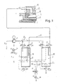
- the equipment in question serves to collect and remove water, with any sediments contained in it, arriving from the press block or blocks P through flexible tubes, collectors or other apparatus, which are all connected to a suction tube A3 leading to the equipment in question.
- the equipment comprises two preferably transparent containers 1A and 1B, in which there is a vacuum to enable the water and sediments to be sucked from the tube A3; the vacuum in the two transparent containers 1A and 1B is created by a pump 3, particularly a liquid ring pump, which is supplied with pressurized water with a low rate of flow, to provide the seal between the impeller and the pump casing; the number 4 indicates the water supply; 4A indicates a flow controller which controls the actual passage of water; the number 5 indicates a valve for shutting off the supply and 5A indicates a pressure reducer.
- a pump 3 particularly a liquid ring pump, which is supplied with pressurized water with a low rate of flow, to provide the seal between the impeller and the pump casing
- the number 4 indicates the water supply
- 4A indicates a flow controller which controls the actual passage of water
- the number 5 indicates a valve for shutting off the supply
- 5A indicates a pressure reducer.
- the tube A3 is connected to the two containers 1A and 1B, opening from above in the areas 6A and 6B which are provided with suitable partitions.
- the container 1A contains a vacuum and is therefore active, while the container 1B is discharging water and sediment which have been previously sucked into it and accumulated.
- a pneumatically operated suction valve 7 for the container 1A is open, while the identical valve 9 for the container 1B is closed for the purposes of suction and is open towards the exterior.
- the tube A3, running from the press, has a branch which is connected to a pneumatically operated inlet valve 8 for the container 1A, this valve being open, while the identical inlet valve 10 for the container 1B is closed.
- a discharge valve 11 of this container 1A is closed, while the identical valve 13 of the container 1B is open, because the container 1B is discharging.
- the valves 8 to 10, 11 and 13 are pneumatically operated (with an elastic return system), being operated by a source of compressed air with a pressure regulator 12R.
- the use of all these pneumatically operated valves enables the operating logic to be significantly simplified. This is because the compressed air supply valve 12, which is electromagnetically operated and “bistable", according to whether its left-hand coil or its right-hand coil is energized, sends the pressure to the line 12A while the line 12B is in the discharge state, or vice versa. Since all the valves 7, 8, 9, 10, 11 and 13 have the "open” or "closed” function in their operating logic, it is simply necessary to connect the control lines 12A and 12B appropriately, as indicated in the diagram in Fig. 1, to provide a satisfactory automatic control system and the correct switching of the suction and discharge functions between the two containers 1A and 1B.
- valves 8 and 10 and the valves 11 and 13 are chosen in accordance with their functions. Both water and sediment (as well as air) pass through the valves 8 and 10 and through the valves 11 and 13, and therefore the tubes cannot be closed by means of flat gate valves, cone valves, ball valves, or other types. It was therefore decided to use special "clamp" valves which operate by opening or closing - by means of a clamp operated by a pneumatic cylinder - a portion of rubber tube of suitable diameter through which the water and the sediment (and air) pass; these valves have a long service life, and are usually trouble-free.
- the two valves 7 and 9 are not of the aforesaid type, since they are used to create the vacuum in the suction connectors 3A, through which only air passes.
- the two valves 7 and 9 are of the gate type, and are characterized in that each of them, when stopping the suction by the pump 3, allows air to pass into the corresponding container to eliminate the vacuum and allow the corresponding valve 11 or 13 to discharge. It should be remembered that the suction and discharge take place alternately in the two containers.
- the equipment is made from components which are, as far as possible, grouped together in a single structure 14 (see Figs. 2 to 5).
- flexible tubes are used between the pump 3 and the containers 1A and 1B.
- the pump 3 is positioned on the same supporting structure 14 as the containers 1A and 1B, and is fixed there by means of suitable elastic elements.
- the tube 3A connects the pump 3 to the two valves 7 and 9; a vacuum gauge 15 indicates the degree of vacuum present in the containers 1A and 1B alternately.
- the two branches of the tube 3A are positioned at a distance from the inlets of the corresponding vacuum tubes 3A, in areas 6A and 6B which are suitably shielded, to prevent the risk of direct suction of water (and sediment) by the pump 3.
- a tube 16 serves to discharge the water for maintaining the seal of the pump 3. The water arriving from the supply 4, and the air which is sucked in by the pump after having passed from the tube 3A through the active container and the pump, are discharged along the said tube 16.
- Two maximum level detectors S1A and S1B (Figs. 3 and 5), for the containers 1A and 1B respectively, detect the maximum level of the liquid in the corresponding containers.
- the operation is switched from this container to the other one during the first stage of rotation of the mold support of the press; it is preferable for the changeover to be carried out at this stage, because no pressing is taking place and thus, even if there is a brief interruption of the vacuum, this has no effect on the quality of the product.
Landscapes
- Engineering & Computer Science (AREA)
- Manufacturing & Machinery (AREA)
- Chemical & Material Sciences (AREA)
- Ceramic Engineering (AREA)
- Mechanical Engineering (AREA)
- Processing Of Solid Wastes (AREA)
- Devices For Post-Treatments, Processing, Supply, Discharge, And Other Processes (AREA)
- Preparation Of Clay, And Manufacture Of Mixtures Containing Clay Or Cement (AREA)
- Jet Pumps And Other Pumps (AREA)
Applications Claiming Priority (2)
| Application Number | Priority Date | Filing Date | Title |
|---|---|---|---|
| ITFI20010240 | 2001-12-18 | ||
| ITFI20010240 ITFI20010240A1 (it) | 2001-12-18 | 2001-12-18 | Apparecchiatura per lo smaltimento di acqua con sedimenti dagli stampi per la produzione di mattonelle di cemento monostrato |
Publications (3)
| Publication Number | Publication Date |
|---|---|
| EP1321258A2 true EP1321258A2 (fr) | 2003-06-25 |
| EP1321258A3 EP1321258A3 (fr) | 2004-05-12 |
| EP1321258B1 EP1321258B1 (fr) | 2006-03-22 |
Family
ID=11442305
Family Applications (1)
| Application Number | Title | Priority Date | Filing Date |
|---|---|---|---|
| EP20020425765 Expired - Lifetime EP1321258B1 (fr) | 2001-12-18 | 2002-12-12 | Equipement pour évacuer l'eau et les sédiments de moules pour la fabrication de carreaux minces en ciment |
Country Status (4)
| Country | Link |
|---|---|
| EP (1) | EP1321258B1 (fr) |
| DE (1) | DE60210040T2 (fr) |
| ES (1) | ES2258138T3 (fr) |
| IT (1) | ITFI20010240A1 (fr) |
Cited By (1)
| Publication number | Priority date | Publication date | Assignee | Title |
|---|---|---|---|---|
| CN104669419A (zh) * | 2015-03-10 | 2015-06-03 | 盐城工学院 | 一种承口托环脱模清理机 |
Family Cites Families (2)
| Publication number | Priority date | Publication date | Assignee | Title |
|---|---|---|---|---|
| NL47515C (fr) * | 1935-10-05 | |||
| GB1128166A (en) * | 1965-04-14 | 1968-09-25 | Lacy Hulbert And Company Ltd | Improvements in drying apparatus |
-
2001
- 2001-12-18 IT ITFI20010240 patent/ITFI20010240A1/it unknown
-
2002
- 2002-12-12 DE DE2002610040 patent/DE60210040T2/de not_active Expired - Lifetime
- 2002-12-12 ES ES02425765T patent/ES2258138T3/es not_active Expired - Lifetime
- 2002-12-12 EP EP20020425765 patent/EP1321258B1/fr not_active Expired - Lifetime
Cited By (2)
| Publication number | Priority date | Publication date | Assignee | Title |
|---|---|---|---|---|
| CN104669419A (zh) * | 2015-03-10 | 2015-06-03 | 盐城工学院 | 一种承口托环脱模清理机 |
| CN104669419B (zh) * | 2015-03-10 | 2017-04-26 | 盐城工学院 | 一种承口托环脱模清理机 |
Also Published As
| Publication number | Publication date |
|---|---|
| ES2258138T3 (es) | 2006-08-16 |
| DE60210040D1 (de) | 2006-05-11 |
| EP1321258B1 (fr) | 2006-03-22 |
| DE60210040T2 (de) | 2007-02-22 |
| ITFI20010240A1 (it) | 2003-06-18 |
| EP1321258A3 (fr) | 2004-05-12 |
Similar Documents
| Publication | Publication Date | Title |
|---|---|---|
| US5667683A (en) | Backwashable liquid filter system using rotating spray | |
| US10280063B2 (en) | Pressurized transfer device | |
| KR20000062259A (ko) | 유체 이송 시스템 | |
| KR100870708B1 (ko) | 여과포 상하반전 이동식 필터프레스 | |
| US4172790A (en) | Diaphragm-containing type filter press | |
| KR20210142682A (ko) | 배양 시스템, 배양 장치, 및 다층 배양 용기 조작 장치 | |
| US20050005968A1 (en) | Automated vacuum waste handling system | |
| EP1321258B1 (fr) | Equipement pour évacuer l'eau et les sédiments de moules pour la fabrication de carreaux minces en ciment | |
| US5182017A (en) | Filtrate separating device with flexible deformable liquid and gas impermeable wall | |
| GB1589402A (en) | Press for expelling liquid from batches of goods | |
| CN109806637A (zh) | 一种用于纺织品染色的过滤机 | |
| JPH04501375A (ja) | 圧力ろ過機の作動装置 | |
| JPS6329113B2 (fr) | ||
| LT3823B (en) | A device for handling of bulk material | |
| CN112807802B (zh) | 一种化工厂用污水处理设备及其处理工艺 | |
| CN209550186U (zh) | 一种气动清洗机 | |
| CN211676594U (zh) | 电动抽滤装置 | |
| NO803214L (no) | Transportinnretning for vaesker. | |
| CN213020516U (zh) | 一种可自清洗的冷却机 | |
| CN215962495U (zh) | 一种双锥式自动卸料过滤器 | |
| JP4015794B2 (ja) | 濾過装置 | |
| CN115804976A (zh) | 一种自动过滤橱柜 | |
| JP2001170834A (ja) | 水抜き装置 | |
| CN221933827U (zh) | 一种熔体滤芯清洗剂配置系统 | |
| RU2144511C1 (ru) | Устройство для очистки воды от нефтепродуктов |
Legal Events
| Date | Code | Title | Description |
|---|---|---|---|
| PUAI | Public reference made under article 153(3) epc to a published international application that has entered the european phase |
Free format text: ORIGINAL CODE: 0009012 |
|
| AK | Designated contracting states |
Designated state(s): AT BE BG CH CY CZ DE DK EE ES FI FR GB GR IE IT LI LU MC NL PT SE SI SK TR |
|
| AX | Request for extension of the european patent |
Extension state: AL LT LV MK RO |
|
| PUAL | Search report despatched |
Free format text: ORIGINAL CODE: 0009013 |
|
| AK | Designated contracting states |
Kind code of ref document: A3 Designated state(s): AT BE BG CH CY CZ DE DK EE ES FI FR GB GR IE IT LI LU MC NL PT SE SI SK TR |
|
| AX | Request for extension of the european patent |
Extension state: AL LT LV MK RO |
|
| RIC1 | Information provided on ipc code assigned before grant |
Ipc: 7B 28B 7/38 A Ipc: 7B 08B 3/00 B Ipc: 7B 28B 7/46 B |
|
| 17P | Request for examination filed |
Effective date: 20041105 |
|
| AKX | Designation fees paid |
Designated state(s): DE ES IT |
|
| 17Q | First examination report despatched |
Effective date: 20050519 |
|
| GRAP | Despatch of communication of intention to grant a patent |
Free format text: ORIGINAL CODE: EPIDOSNIGR1 |
|
| GRAS | Grant fee paid |
Free format text: ORIGINAL CODE: EPIDOSNIGR3 |
|
| GRAA | (expected) grant |
Free format text: ORIGINAL CODE: 0009210 |
|
| AK | Designated contracting states |
Kind code of ref document: B1 Designated state(s): DE ES IT |
|
| REF | Corresponds to: |
Ref document number: 60210040 Country of ref document: DE Date of ref document: 20060511 Kind code of ref document: P |
|
| REG | Reference to a national code |
Ref country code: ES Ref legal event code: FG2A Ref document number: 2258138 Country of ref document: ES Kind code of ref document: T3 |
|
| PLBE | No opposition filed within time limit |
Free format text: ORIGINAL CODE: 0009261 |
|
| STAA | Information on the status of an ep patent application or granted ep patent |
Free format text: STATUS: NO OPPOSITION FILED WITHIN TIME LIMIT |
|
| 26N | No opposition filed |
Effective date: 20061227 |
|
| REG | Reference to a national code |
Ref country code: DE Ref legal event code: R082 Ref document number: 60210040 Country of ref document: DE Representative=s name: GLAWE DELFS MOLL - PARTNERSCHAFT VON PATENT- U, DE Effective date: 20120920 Ref country code: DE Ref legal event code: R081 Ref document number: 60210040 Country of ref document: DE Owner name: GE.BI.LON. GESTIONE BREVETTI & IMMOBILI LONGIN, IT Free format text: FORMER OWNER: LONGINOTTI MECCANICA S.R.L., SESTO FIORENTINO, IT Effective date: 20120920 Ref country code: DE Ref legal event code: R081 Ref document number: 60210040 Country of ref document: DE Owner name: GE.BI.LON. GESTIONE BREVETTI & IMMOBILI LONGIN, IT Free format text: FORMER OWNER: LONGINOTTI MECCANICA S.R.L., SESTO FIORENTINO, FIRENZE, IT Effective date: 20120920 Ref country code: DE Ref legal event code: R082 Ref document number: 60210040 Country of ref document: DE Representative=s name: GLAWE DELFS MOLL PARTNERSCHAFT MBB VON PATENT-, DE Effective date: 20120920 |
|
| PGFP | Annual fee paid to national office [announced via postgrant information from national office to epo] |
Ref country code: IT Payment date: 20191126 Year of fee payment: 18 |
|
| PGFP | Annual fee paid to national office [announced via postgrant information from national office to epo] |
Ref country code: ES Payment date: 20200102 Year of fee payment: 18 Ref country code: DE Payment date: 20200224 Year of fee payment: 18 |
|
| REG | Reference to a national code |
Ref country code: DE Ref legal event code: R119 Ref document number: 60210040 Country of ref document: DE |
|
| PG25 | Lapsed in a contracting state [announced via postgrant information from national office to epo] |
Ref country code: IT Free format text: LAPSE BECAUSE OF NON-PAYMENT OF DUE FEES Effective date: 20201212 |
|
| PG25 | Lapsed in a contracting state [announced via postgrant information from national office to epo] |
Ref country code: DE Free format text: LAPSE BECAUSE OF NON-PAYMENT OF DUE FEES Effective date: 20210701 |
|
| REG | Reference to a national code |
Ref country code: ES Ref legal event code: FD2A Effective date: 20220214 |
|
| PG25 | Lapsed in a contracting state [announced via postgrant information from national office to epo] |
Ref country code: ES Free format text: LAPSE BECAUSE OF NON-PAYMENT OF DUE FEES Effective date: 20201213 |