EP1321276B1 - Machine de moulage par injection avec accumulateur hydraulique - Google Patents
Machine de moulage par injection avec accumulateur hydraulique Download PDFInfo
- Publication number
- EP1321276B1 EP1321276B1 EP02028562A EP02028562A EP1321276B1 EP 1321276 B1 EP1321276 B1 EP 1321276B1 EP 02028562 A EP02028562 A EP 02028562A EP 02028562 A EP02028562 A EP 02028562A EP 1321276 B1 EP1321276 B1 EP 1321276B1
- Authority
- EP
- European Patent Office
- Prior art keywords
- pressure
- hydraulic
- operating parameter
- moulding machine
- injection moulding
- Prior art date
- Legal status (The legal status is an assumption and is not a legal conclusion. Google has not performed a legal analysis and makes no representation as to the accuracy of the status listed.)
- Expired - Lifetime
Links
- 238000001746 injection moulding Methods 0.000 title claims abstract description 72
- 238000005259 measurement Methods 0.000 claims abstract description 5
- 238000002347 injection Methods 0.000 claims description 43
- 239000007924 injection Substances 0.000 claims description 43
- 230000006870 function Effects 0.000 claims description 12
- 238000009825 accumulation Methods 0.000 claims 1
- 239000012530 fluid Substances 0.000 description 17
- 238000000034 method Methods 0.000 description 5
- 238000012544 monitoring process Methods 0.000 description 5
- 230000000694 effects Effects 0.000 description 4
- 230000008569 process Effects 0.000 description 4
- 230000002411 adverse Effects 0.000 description 3
- 230000008901 benefit Effects 0.000 description 3
- 238000004891 communication Methods 0.000 description 3
- 238000006073 displacement reaction Methods 0.000 description 3
- 238000012545 processing Methods 0.000 description 3
- 239000007921 spray Substances 0.000 description 3
- 230000008859 change Effects 0.000 description 2
- 238000013461 design Methods 0.000 description 2
- 238000011161 development Methods 0.000 description 2
- 238000010586 diagram Methods 0.000 description 2
- 239000000155 melt Substances 0.000 description 2
- 238000000465 moulding Methods 0.000 description 2
- 238000006243 chemical reaction Methods 0.000 description 1
- 238000005352 clarification Methods 0.000 description 1
- 238000010276 construction Methods 0.000 description 1
- 238000013500 data storage Methods 0.000 description 1
- 230000001419 dependent effect Effects 0.000 description 1
- 238000001514 detection method Methods 0.000 description 1
- 238000005265 energy consumption Methods 0.000 description 1
- 230000007613 environmental effect Effects 0.000 description 1
- 230000002349 favourable effect Effects 0.000 description 1
- 238000009434 installation Methods 0.000 description 1
- 230000010354 integration Effects 0.000 description 1
- 239000000463 material Substances 0.000 description 1
- 230000007935 neutral effect Effects 0.000 description 1
- 229920003023 plastic Polymers 0.000 description 1
- 239000004033 plastic Substances 0.000 description 1
- 230000009467 reduction Effects 0.000 description 1
- 238000010992 reflux Methods 0.000 description 1
- 238000005507 spraying Methods 0.000 description 1
- 230000001360 synchronised effect Effects 0.000 description 1
- 238000012549 training Methods 0.000 description 1
Images


Classifications
-
- B—PERFORMING OPERATIONS; TRANSPORTING
- B29—WORKING OF PLASTICS; WORKING OF SUBSTANCES IN A PLASTIC STATE IN GENERAL
- B29C—SHAPING OR JOINING OF PLASTICS; SHAPING OF MATERIAL IN A PLASTIC STATE, NOT OTHERWISE PROVIDED FOR; AFTER-TREATMENT OF THE SHAPED PRODUCTS, e.g. REPAIRING
- B29C45/00—Injection moulding, i.e. forcing the required volume of moulding material through a nozzle into a closed mould; Apparatus therefor
- B29C45/17—Component parts, details or accessories; Auxiliary operations
- B29C45/76—Measuring, controlling or regulating
- B29C45/82—Hydraulic or pneumatic circuits
-
- G—PHYSICS
- G05—CONTROLLING; REGULATING
- G05D—SYSTEMS FOR CONTROLLING OR REGULATING NON-ELECTRIC VARIABLES
- G05D16/00—Control of fluid pressure
- G05D16/20—Control of fluid pressure characterised by the use of electric means
- G05D16/2006—Control of fluid pressure characterised by the use of electric means with direct action of electric energy on controlling means
- G05D16/2066—Control of fluid pressure characterised by the use of electric means with direct action of electric energy on controlling means using controlling means acting on the pressure source
-
- B—PERFORMING OPERATIONS; TRANSPORTING
- B29—WORKING OF PLASTICS; WORKING OF SUBSTANCES IN A PLASTIC STATE IN GENERAL
- B29C—SHAPING OR JOINING OF PLASTICS; SHAPING OF MATERIAL IN A PLASTIC STATE, NOT OTHERWISE PROVIDED FOR; AFTER-TREATMENT OF THE SHAPED PRODUCTS, e.g. REPAIRING
- B29C45/00—Injection moulding, i.e. forcing the required volume of moulding material through a nozzle into a closed mould; Apparatus therefor
- B29C45/17—Component parts, details or accessories; Auxiliary operations
- B29C45/76—Measuring, controlling or regulating
- B29C45/82—Hydraulic or pneumatic circuits
- B29C2045/824—Accumulators
-
- B—PERFORMING OPERATIONS; TRANSPORTING
- B29—WORKING OF PLASTICS; WORKING OF SUBSTANCES IN A PLASTIC STATE IN GENERAL
- B29C—SHAPING OR JOINING OF PLASTICS; SHAPING OF MATERIAL IN A PLASTIC STATE, NOT OTHERWISE PROVIDED FOR; AFTER-TREATMENT OF THE SHAPED PRODUCTS, e.g. REPAIRING
- B29C2945/00—Indexing scheme relating to injection moulding, i.e. forcing the required volume of moulding material through a nozzle into a closed mould
- B29C2945/76—Measuring, controlling or regulating
- B29C2945/76003—Measured parameter
- B29C2945/76006—Pressure
-
- B—PERFORMING OPERATIONS; TRANSPORTING
- B29—WORKING OF PLASTICS; WORKING OF SUBSTANCES IN A PLASTIC STATE IN GENERAL
- B29C—SHAPING OR JOINING OF PLASTICS; SHAPING OF MATERIAL IN A PLASTIC STATE, NOT OTHERWISE PROVIDED FOR; AFTER-TREATMENT OF THE SHAPED PRODUCTS, e.g. REPAIRING
- B29C2945/00—Indexing scheme relating to injection moulding, i.e. forcing the required volume of moulding material through a nozzle into a closed mould
- B29C2945/76—Measuring, controlling or regulating
- B29C2945/76003—Measured parameter
- B29C2945/76013—Force
-
- B—PERFORMING OPERATIONS; TRANSPORTING
- B29—WORKING OF PLASTICS; WORKING OF SUBSTANCES IN A PLASTIC STATE IN GENERAL
- B29C—SHAPING OR JOINING OF PLASTICS; SHAPING OF MATERIAL IN A PLASTIC STATE, NOT OTHERWISE PROVIDED FOR; AFTER-TREATMENT OF THE SHAPED PRODUCTS, e.g. REPAIRING
- B29C2945/00—Indexing scheme relating to injection moulding, i.e. forcing the required volume of moulding material through a nozzle into a closed mould
- B29C2945/76—Measuring, controlling or regulating
- B29C2945/76003—Measured parameter
- B29C2945/76083—Position
- B29C2945/76096—Distance
-
- B—PERFORMING OPERATIONS; TRANSPORTING
- B29—WORKING OF PLASTICS; WORKING OF SUBSTANCES IN A PLASTIC STATE IN GENERAL
- B29C—SHAPING OR JOINING OF PLASTICS; SHAPING OF MATERIAL IN A PLASTIC STATE, NOT OTHERWISE PROVIDED FOR; AFTER-TREATMENT OF THE SHAPED PRODUCTS, e.g. REPAIRING
- B29C2945/00—Indexing scheme relating to injection moulding, i.e. forcing the required volume of moulding material through a nozzle into a closed mould
- B29C2945/76—Measuring, controlling or regulating
- B29C2945/76003—Measured parameter
- B29C2945/7611—Velocity
-
- B—PERFORMING OPERATIONS; TRANSPORTING
- B29—WORKING OF PLASTICS; WORKING OF SUBSTANCES IN A PLASTIC STATE IN GENERAL
- B29C—SHAPING OR JOINING OF PLASTICS; SHAPING OF MATERIAL IN A PLASTIC STATE, NOT OTHERWISE PROVIDED FOR; AFTER-TREATMENT OF THE SHAPED PRODUCTS, e.g. REPAIRING
- B29C2945/00—Indexing scheme relating to injection moulding, i.e. forcing the required volume of moulding material through a nozzle into a closed mould
- B29C2945/76—Measuring, controlling or regulating
- B29C2945/76177—Location of measurement
- B29C2945/7618—Injection unit
- B29C2945/762—Injection unit injection piston
-
- B—PERFORMING OPERATIONS; TRANSPORTING
- B29—WORKING OF PLASTICS; WORKING OF SUBSTANCES IN A PLASTIC STATE IN GENERAL
- B29C—SHAPING OR JOINING OF PLASTICS; SHAPING OF MATERIAL IN A PLASTIC STATE, NOT OTHERWISE PROVIDED FOR; AFTER-TREATMENT OF THE SHAPED PRODUCTS, e.g. REPAIRING
- B29C2945/00—Indexing scheme relating to injection moulding, i.e. forcing the required volume of moulding material through a nozzle into a closed mould
- B29C2945/76—Measuring, controlling or regulating
- B29C2945/76177—Location of measurement
- B29C2945/76224—Closure or clamping unit
- B29C2945/7623—Closure or clamping unit clamping or closing drive means
-
- B—PERFORMING OPERATIONS; TRANSPORTING
- B29—WORKING OF PLASTICS; WORKING OF SUBSTANCES IN A PLASTIC STATE IN GENERAL
- B29C—SHAPING OR JOINING OF PLASTICS; SHAPING OF MATERIAL IN A PLASTIC STATE, NOT OTHERWISE PROVIDED FOR; AFTER-TREATMENT OF THE SHAPED PRODUCTS, e.g. REPAIRING
- B29C2945/00—Indexing scheme relating to injection moulding, i.e. forcing the required volume of moulding material through a nozzle into a closed mould
- B29C2945/76—Measuring, controlling or regulating
- B29C2945/76177—Location of measurement
- B29C2945/76254—Mould
- B29C2945/76257—Mould cavity
-
- B—PERFORMING OPERATIONS; TRANSPORTING
- B29—WORKING OF PLASTICS; WORKING OF SUBSTANCES IN A PLASTIC STATE IN GENERAL
- B29C—SHAPING OR JOINING OF PLASTICS; SHAPING OF MATERIAL IN A PLASTIC STATE, NOT OTHERWISE PROVIDED FOR; AFTER-TREATMENT OF THE SHAPED PRODUCTS, e.g. REPAIRING
- B29C2945/00—Indexing scheme relating to injection moulding, i.e. forcing the required volume of moulding material through a nozzle into a closed mould
- B29C2945/76—Measuring, controlling or regulating
- B29C2945/76177—Location of measurement
- B29C2945/76254—Mould
- B29C2945/76274—Mould runners, nozzles
-
- B—PERFORMING OPERATIONS; TRANSPORTING
- B29—WORKING OF PLASTICS; WORKING OF SUBSTANCES IN A PLASTIC STATE IN GENERAL
- B29C—SHAPING OR JOINING OF PLASTICS; SHAPING OF MATERIAL IN A PLASTIC STATE, NOT OTHERWISE PROVIDED FOR; AFTER-TREATMENT OF THE SHAPED PRODUCTS, e.g. REPAIRING
- B29C2945/00—Indexing scheme relating to injection moulding, i.e. forcing the required volume of moulding material through a nozzle into a closed mould
- B29C2945/76—Measuring, controlling or regulating
- B29C2945/76494—Controlled parameter
- B29C2945/76498—Pressure
-
- B—PERFORMING OPERATIONS; TRANSPORTING
- B29—WORKING OF PLASTICS; WORKING OF SUBSTANCES IN A PLASTIC STATE IN GENERAL
- B29C—SHAPING OR JOINING OF PLASTICS; SHAPING OF MATERIAL IN A PLASTIC STATE, NOT OTHERWISE PROVIDED FOR; AFTER-TREATMENT OF THE SHAPED PRODUCTS, e.g. REPAIRING
- B29C2945/00—Indexing scheme relating to injection moulding, i.e. forcing the required volume of moulding material through a nozzle into a closed mould
- B29C2945/76—Measuring, controlling or regulating
- B29C2945/76494—Controlled parameter
- B29C2945/76595—Velocity
-
- B—PERFORMING OPERATIONS; TRANSPORTING
- B29—WORKING OF PLASTICS; WORKING OF SUBSTANCES IN A PLASTIC STATE IN GENERAL
- B29C—SHAPING OR JOINING OF PLASTICS; SHAPING OF MATERIAL IN A PLASTIC STATE, NOT OTHERWISE PROVIDED FOR; AFTER-TREATMENT OF THE SHAPED PRODUCTS, e.g. REPAIRING
- B29C2945/00—Indexing scheme relating to injection moulding, i.e. forcing the required volume of moulding material through a nozzle into a closed mould
- B29C2945/76—Measuring, controlling or regulating
- B29C2945/76655—Location of control
- B29C2945/76775—Fluids
- B29C2945/76785—Fluids hydraulic fluids
-
- B—PERFORMING OPERATIONS; TRANSPORTING
- B29—WORKING OF PLASTICS; WORKING OF SUBSTANCES IN A PLASTIC STATE IN GENERAL
- B29C—SHAPING OR JOINING OF PLASTICS; SHAPING OF MATERIAL IN A PLASTIC STATE, NOT OTHERWISE PROVIDED FOR; AFTER-TREATMENT OF THE SHAPED PRODUCTS, e.g. REPAIRING
- B29C2945/00—Indexing scheme relating to injection moulding, i.e. forcing the required volume of moulding material through a nozzle into a closed mould
- B29C2945/76—Measuring, controlling or regulating
- B29C2945/76929—Controlling method
- B29C2945/76939—Using stored or historical data sets
- B29C2945/76943—Using stored or historical data sets compare with thresholds
Definitions
- Hydraulic systems with hydraulic accumulator as they are particularly suitable for use in conjunction with high-performance injection molding machines, usually come with a single hydraulic pump; the hydraulic fluid accumulated in the hydraulic accumulator by means of the hydraulic pump, the stored energy of which enables, for example, particularly rapid closing movements and / or spraying movements and thus particularly short cycles, is directed to the individual consumers via valves controlled by a control unit, possibly also in parallel.
- hydraulic systems without hydraulic accumulator - if only one hydraulic pump is provided - the individual consumers often fed serially in succession, which can lead to undesirably long cycles.
- injection molding machines without hydraulic accumulators also provide a plurality of hydraulic pumps, each of which feeds individual hydraulic consumers assigned to them and which are matched with regard to their performance data to the specific consumers. In this case, several hydraulic consumers can easily be operated in parallel; However, such injection molding machines with multiple hydraulic pumps are technically complicated and expensive.
- Injection molding machines of the type specified ie with hydraulic accumulator, are widely used within the plastics processing industry.
- the company publication "The K-TEC Series - With Closing Forces of 400 kN to 4500 kN" by Ferromatik Milacron Maschinenbau GmbH, D-79364 Malterdingen refers to such injection molding machines.
- About the hydraulic accumulator is within a spray cycle (in particular for closing the mold, injecting the melt, pressing, opening the mold and Ejecting the molding) significantly fluctuating demand of at least one hydraulic consumer buffered.
- the hydraulic pump thus does not need to be designed with respect to its capacity to the maximum demand for hydraulic fluid; Rather, in a more or less continuously operated hydraulic pump, an essentially oriented to the average demand for hydraulic fluid interpretation, wherein the hydraulic accumulator is loaded within a spray cycle in phases of low demand for hydraulic fluid and in phases of high demand for hydraulic fluid, the at least one hydraulic consumer fed.
- the hydraulic pump feeding hydraulic pump is controlled in neutral circulation when the pressure in the hydraulic accumulator reaches a maximum value.
- the concrete profile for the demand for hydraulic fluid within an injection cycle depends on the individual injection molding process. In particular, depending on the type of injection molding different amounts of hydraulic fluid for closing the mold, that injection of the melt, that requires opening of the mold, the core pulling and the ejection of the molding. If, for the injection molding process in question, the average demand for hydraulic fluid is below the design point of the delivery rate of the hydraulic pump, the hydraulic accumulator is intermittently charged, in the case of a continuous or discontinuous hydraulic pump, the hydraulic pump for charging the hydraulic accumulator at one of a pressure sensor, as stated at the outset determined lower pressure limit (eg 180 bar) in the hydraulic system and switchable at a from the Pressure sensor determined upper pressure limit (eg 195 bar) can be switched off.
- a pressure sensor as stated at the outset determined lower pressure limit (eg 180 bar) in the hydraulic system and switchable at a from the Pressure sensor determined upper pressure limit (eg 195 bar) can be switched off.
- the present invention seeks to provide an injection molding machine of the type described, which is characterized by a high energy efficiency and at a relatively low technical and procedural complexity and a relatively high tolerance to fluctuating operating parameters characterized by low wear.
- an injection molding machine of the generic type in that the injection molding machine has at least one designed as a pressure transducer, as a force transducer or as Wegmeßsystem Radiometeraufêt, which is in communication with the control unit and during at least one measurement cycle 'measured values to the at least reports a monitored operating parameter to the control unit, wherein the control unit sets at least one of the two pressure limit values as a function of the measured values recorded by the at least one operating parameter sensor.
- the injection molding machine according to the invention is thus based on the proven, robust and tolerant of fluctuations in operating parameters concept that the loading of the hydraulic accumulator directly in dependence is controlled by the in the hydraulic system, for example in the hydraulic accumulator itself prevailing pressure, in particular by the control unit for charging the hydraulic accumulator, the hydraulic pump on reaching a lower pressure limit switches on and off upon reaching an upper pressure limit.
- the two pressure limits are not fixed; Rather, at least one of the two pressure limit values is set individually by the control unit for the specific injection cycle as a function of measured values of at least one operating parameter which are determined by an operating parameter recorder during at least one measuring cycle and processed in the control unit.
- Both pressure limit values ie both the lower pressure limit relevant for starting the charging of the hydraulic accumulator and the upper limit for the end of charging of the hydraulic accumulator, are determined individually for the specific injection cycle as a function of measured values of at least one operating parameter during at least one measuring cycle be determined by a Radiometerauf commentary and processed in the control unit.
- the injection molding machine according to the invention thus adapts, without the basic concept is abandoned, the loading of the hydraulic accumulator automatically to the individual, relevant for the respective injection molding injection cycle, so that in particular an unfavorable under energetic aspects and wear-promoting loading of the hydraulic accumulator over that for the relevant Spray cycle required pressure is avoided.
- the storage volume of the at least one hydraulic accumulator is variable independently of the two pressure limit values, wherein the control unit determines the effective size of the storage volume as a function of the measured values detected by the at least one operating parameter receiver.
- a particularly preferred possibility of being able to vary the storage volume of the at least one hydraulic accumulator independently of the pressure conditions lies in a variation of the pre-charge pressure of the at least one hydraulic accumulator. This will be explained in more detail below.
- the at least one variable pressure limit value measured values for a wide variety of operating parameters can be evaluated using corresponding suitable operating parameter sensors known as such.
- Priority come as Radioparameteraufumble pressure sensor, load cell and position measuring systems are used; However, for example, speed sensors and other position detection means may also be considered as operating parameter sensors as distance measuring systems.
- the at least one operating parameter sensor is designed as a pressure sensor, it can monitor, in particular as an operating parameter, the pressure in the tool, in the runner or in the injection cylinder and / or the pressure in the lock cylinder. If, on the other hand, the at least one operating parameter sensor is designed as a force transducer, it can monitor the closing force of the clamping unit as the operating parameter.
- the at least one operating parameter sensor is designed as a position measuring system, then it can monitor in particular the feed of the injection screw and / or the closing path of the closing unit as the operating parameter. Regardless of which type of operating parameter pickup is now and which operating parameter is concretely monitored with it, in each case the measured value is compared with a setpoint value stored in the control unit for the relevant operating parameter. differs the measured value by an intolerable measure of the stored setpoint, the control unit automatically adapts the at least one variable pressure limit in the sense of reducing the deviation of the actual value of the monitored operating parameter from the corresponding setpoint. For example, if the monitored by means of a pressure transducer actual pressure in the lock cylinder remains behind the stored in the control unit setpoint, the upper, relevant for terminating the loading of the hydraulic accumulator pressure limit be raised automatically by the control unit.
- the setpoint does not necessarily have to refer to the maximum closing pressure. Rather, it is also possible to monitor a reference pressure (operating parameter) lying before the maximum closing pressure is reached. This is especially true for such injection molding machines according to the invention, in which only a portion of the hydraulic fluid required for the construction of the maximum closing pressure comes from the hydraulic accumulator, the remaining part, however, directly from the hydraulic pump or a pressure booster. In this case, for example, the pressure which arises solely from the feeding of the closing unit from the hydraulic accumulator could be used as the reference pressure.
- the at least one measuring cycle can in the context of the present invention include both an empty cycle without injection and a working cycle Be injection. Also, a combination of both options is considered by basic settings for the relevant relevant for the specific injection molding injection cycle are determined in the context of an empty cycle and in the operation of the injection molding machine compliance with the specified operating parameters is monitored continuously and, if necessary, the settings made are tracked.
- the injection molding machine has a memory unit for storing the at least one variable, for the specific spray program set by the control unit pressure limit and, if necessary, the effective storage volume on a data storage.
- the corresponding specific for the individual injection molding data can be easily stored in this way in a conversion of the injection molding of an injection molding process to another injection molding process in the control unit. This makes it unnecessary to repeat an idle cycle for determining the setpoint values for the at least one monitored operating parameter and thus contributes to short set-up times.
- the present invention is equally applicable to such injection molding machines which have a single, cohesive hydraulic system, as well as to those injection molding machines in which the hydraulic system comprises a plurality of demarcated subsystems, each associated with one or more functions and at least one each Include hydraulic accumulator has. Nor does it play for the technical implementation of the present invention, a role, whether the at least one hydraulic consumer acted solely on the hydraulic accumulator or, according to a preferred embodiment of the present invention, by means of a valve via a direct connection of the hydraulic pump can be acted upon.
- Yet another preferred development of the injection molding machine according to the invention is characterized by a mode switch, by means of which the pressure limit values defined by the control unit can be replaced by other pressure limit values.
- a mode switch by means of which the pressure limit values defined by the control unit can be replaced by other pressure limit values. This proves, for example, as low in such injection molding machines, which are regularly switched to a standby mode; in that case, by operating the mode switch, the pressure limits established by the operating mode control unit can be temporarily replaced by reduced pressure limits for standby mode, which is advantageous both in terms of energy consumption of the injection molding machine and material conservation.
- the illustrated in Fig. 1 injection molding machine comprises a fixed platen 1 and a movable platen 2, which together define the tool installation space 3.
- a closing unit 4 On the movable platen 2 acts a closing unit 4. This is carried out in two stages, comprising separate hydraulic cylinders for the express drive on the one hand and the power drive on the other. In this sense acts on the movable platen 2 of the force closing causing lock cylinder 5, which is supported on an end plate 6.
- On the end plate 6 in turn act on the rapid feed driving cylinder 7, the pistons are arranged on tie rods 8, which are fixedly connected to the fixed platen 1 and on which the movable platen 2 and the end plate 6 are guided.
- the drive of the worm 12 is a hydraulic motor 13, which is mounted on a motor carrier 14.
- About injection cylinder 15 is the engine mount 14 with the worm cylinder receptacle 9 in connection.
- the hydraulic system of the injection molding machine according to FIG. 1 comprises a hydraulic pump 16, which is driven by a motor 17.
- the hydraulic pump 16 delivers hydraulic fluid from the tank 18 via a check valve 19 into the high-pressure line 20.
- the low-pressure line 21 is opened via the return line 22 to the tank 18.
- the high-pressure line 20 communicates with a hydraulic accumulator 23. Furthermore, a pressure sensor 24 is connected to the high-pressure line 20. This is connected via a signal line 25 to a control unit 26 in connection. Depending on the prevailing in the high-pressure line 20, buffered via the pressure accumulator 23 pressure, the control unit 26 switches the hydraulic pump 16 such that the hydraulic pump 16 when falling below a lower pressure limit in the high-pressure line 20 for charging the pressure accumulator 23 is switched on and Reaching or exceeding an upper pressure limit in the high-pressure line 20 is switched off, d. H. is switched to zero promotion at further running drive motor 17.
- the hydraulic accumulator 23 with the high pressure line 20 connecting line can - without this being illustrated in the drawing - be provided a valve which is controllable by the control unit.
- the line in question can be locked to selectively block the loading of the hydraulic accumulator 23 in certain operating conditions, for example, at a comparatively low pressure level in the hydraulic accumulator the hydraulic consumer to apply directly at high pressure with the entire flow rate of the hydraulic pump 16.
- the injection molding machine according to Fig. 1 thus comprises a total of five functionally different hydraulic consumers, which are each acted upon in accordance with the respective injection molding process via a control unit - not shown - control valve 27 with hydraulic fluid from the high-pressure line 20.
- the injection molding machine according to FIG. 1 corresponds to the well-known state of the art, so that further explanations are not required.
- the injection molding machine according to the present invention further comprises an operating parameter receiver 28, which in the case of the illustrated embodiment is designed as a displacement transducer 29, which is arranged between the stationary mold clamping plate 1 and the end plate 6. Via a signal line 30, the displacement sensor 29 is connected to the control unit 26.
- the control unit 26 is enabled, in the context of the control of the hydraulic pump 16 in addition to the pressure signal provided by the pressure sensor 24 regarding the pressure in the high-pressure line 20 and the monitored by the Radioparameteraufillon 28 operating parameters, in this case determined by the transducer 29 Position of the movable plate 2 relative to the fixed platen 1, to be considered.
- the processing of the signals of the pressure sensor 24 on the one hand and the transducer 29 on the other hand can be done in particular such that the pressure sensor on the Detected end of the closing movement of the movable plate 2 in the high pressure line 20 prevailing pressure, wherein that end of the closing movement of the movable plate 2 is detected by the transducer 29.
- the existing at that operating pressure in the high pressure line 20 is compared with a stored in the control unit 26 reference pressure. If the actual pressure exceeds the reference pressure, the upper pressure limit is automatically corrected downwards. If, however, the actual pressure falls short of the reference pressure, the upper pressure limit is raised accordingly.
- other or further operating parameter sensors may be provided which are correspondingly in communication with the control unit 26 and the measured values of the respectively monitored operating parameter for processing within the determination of the respectively most favorable upper and / or lower pressure limit value provide.
- the upper and / or the lower pressure limit value are automatically determined by a routine implemented in the control unit, taking into account the measured value / measured values provided by the respective operating parameter recorder (s) with respect to FIG optimized injection molding process. Due to the principle comparable operation of corresponding alternatives with the embodiment described above can be dispensed with a detailed explanation.
- control unit 26 is a mode switch 31 in connection.
- the operating mode of the injection molding machine can be changed, for example, by the controller is switched by a simple push of a button corresponding to the operating mode first operating mode in a standby mode corresponding second operating mode, in which - with continued readiness of the injection molding machine - the upper and the lower pressure limit is reduced.
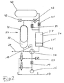
- FIG. 2 illustrates a device for changing the effective storage volume of the at least one hydraulic accumulator 23 by Vorhelldruckvariation regardless of the pressure ratios, as it is particularly preferably used in conjunction with an injection molding machine of the type shown in Fig. 1.
- a high pressure line 20 is fed via a check valve 19 by a hydraulic pump 16.
- a hydraulic accumulator 23 is connected to the high pressure line 20.
- This is designed as a bladder accumulator with a disposed within the housing 32 storage bladder 33.
- the space between the reservoir bladder 33 and the housing 32 serves as a compensation chamber for the accumulated hydraulic fluid, while the bladder 33 itself is filled with a gas.
- the biasing pressure of the compressed gas in the storage bubble 33 can be varied by using the hydraulic pump 16.
- a compressor cylinder 34 is provided, whose freely movable compressor piston 35 separates a hydraulic working chamber 36 from a gas chamber 37.
- the hydraulic working chamber 36 can be acted upon by the hydraulic pump 16 funded hydraulic fluid.
- the gas trapped in the gas space 37 is compressed and, as soon as the pressure prevailing in the reservoir bladder 33 is exceeded, is displaced via the check valve 39 into the reservoir bladder 33.
- the device of Fig. 2 can be used with particular advantage such that, taking into account the optimum pressure limits determined by the controller 26, the effective size of the storage volume of the hydraulic accumulator 23 will depend on those of the operating parameters receivers determined measured values is determined. For example, if the upper pressure limit lowered while reducing the pressure difference between the lower and upper pressure limit, so can by appropriate adjustment of the effective size of the storage volume in the hydraulic accumulator Accumulated amount of hydraulic fluid can be adjusted regardless of the pressure ratios to the actual needs.
- the gas pressure in the reservoir bladder 33 is monitored via a pressure sensor 42. That pressure sensor 42 controls the biasing of the reservoir bladder 33 described above or, if appropriate, the lowering of the prestressing pressure of the reservoir bladder by opening the reflux valve 43 in order to adapt the effective size of the reservoir volume to the respective conditions.
- the pressure sensor 42 controls not only the hydraulic pump 16 but also depending on the various detected operating parameters the 4/2-way switching valve 38 and the return flow 43rd
- the process represented by a flow chart in FIG. 3 can be used to automatically adapt the pressure level of the hydraulic system to the respective injection cycle by monitoring and evaluating at least one operating parameter characterizing the injection cycle .
- the decisive operating parameter used in the illustrated case is the injection speed, ie the speed of the injection movement.
- a setpoint for the injection speed is specified.
- start values for the upper and lower pressure limit values are entered, with which the process illustrated in FIG. 3 is entered.
- the actually achieved injection speed is detected; Similarly, the prevailing at the end of the injection movement injection pressure and accumulator pressure are detected.
- the actually achieved value of the injection speed is compared with the specified setpoint value. If the actual injection speed does not reach the specified setpoint, at least one of the two pressure limits is increased. Whether the lower pressure limit value, the upper pressure limit value or both pressure limit values are increased may result, in particular, as a function of further monitored operating parameters after this has an effect, inter alia, on the effective capacity of the hydraulic accumulator. To simplify the diagram, however, has been dispensed with a representation of the extent to be carried out further query.
- the injection pressure prevailing at the end of the injection movement is compared with the storage pressure prevailing at that time. Only in the case that the accumulator pressure is less than 10 bar above the injection pressure, there is no change in the two pressure limits compared to the initial values specified at the beginning.
Landscapes
- Physics & Mathematics (AREA)
- Engineering & Computer Science (AREA)
- Fluid Mechanics (AREA)
- General Physics & Mathematics (AREA)
- Automation & Control Theory (AREA)
- Manufacturing & Machinery (AREA)
- Mechanical Engineering (AREA)
- Injection Moulding Of Plastics Or The Like (AREA)
Claims (14)
- Machine de moulage par injection, avec une unité de fermeture (4) et au moins une unité de plastification et d'injection, comportant au moins un utilisateur hydraulique (5, 7, 10, 13, 15) actionnable en discontinu, possédant les caractéristiques suivantes :- l'utilisateur hydraulique, au moins au nombre de un, peut être alimenté par au moins un réservoir hydraulique (23), par le biais d'une soupape (27) actionnable au moyen d'une unité de commande (26) ;- le réservoir hydraulique (23), au moins au nombre de un, peut être alimenté par une pompe hydraulique (16) ;- un détecteur de pression (24) relié à l'unité de commande (26) est attribué au réservoir hydraulique (23), au moins au nombre de un, la pompe hydraulique (16) étant fermée au moyen de l'unité de commande (26) lorsque pression surveillée par le détecteur de pression (24) atteint ou dépasse une valeur seuil minimale, et arrêtée lorsque la pression surveillée par le détecteur de pression (24) atteint ou dépasse une valeur seuil maximale;caractérisée par les caractéristiques suivantes:- la machine de moulage par injection comporte au moins un capteur de paramètres de fonctionnement (28) conçu comme un capteur de pression, un capteur de puissance ou un système de mesure de déplacement, qui se trouve en liaison avec l'unité de commande (26) et qui communique des valeurs de mesure concernant le paramètre de fonctionnement surveillé, au moins au nombre de un, à l'unité de commande (26) au cours d'au moins un cycle de mesure ;- l'unité de commande (26) fixe au moins l'une deux valeurs seuil de pression en fonction des valeurs de mesure captées au moyen du capteur de paramètres de fonctionnement.
- Machine de moulage par injection selon la revendication 1,
caractérisée en ce que
le volume de réserve du réservoir hydraulique (23), au moins au nombre de un, est variable indépendamment des rapports de pression dans le réservoir hydraulique (23), l'unité de commande (26) déterminant la taille adéquate du volume de réserve en fonction des valeurs de mesure. - Machine de moulage par injection selon la revendication 2,
caractérisée en ce que
la pression de pré-remplissage du réservoir hydraulique (23), au moins au nombre de un, est variable. - Machine de moulage par injection selon l'une des revendications 1 à 3,
caractérisée en ce que
un capteur de pression est prévu en tant que capteur de paramètres de fonctionnement (28), permettant de surveiller le paramètre de fonctionnement relatif à la pression dans l'outil, dans le canal d'injection ou dans le cylindre d'injection (15). - Machine de moulage par injection selon l'une des revendications 1 à 4,
caractérisée en ce que
un capteur de pression est prévu en tant que capteur de paramètres de fonctionnement (28), permettant de surveiller le paramètre de fonctionnement relatif à la pression dans le cylindre de fermeture (5). - Machine de moulage par injection selon l'une des revendications 1 à 5,
caractérisée en ce que
un capteur de puissance est prévu en tant que capteur de paramètres de fonctionnement (28), permettant de surveiller le paramètre de fonctionnement relatif à la puissance de fermeture de l'unité de fermeture (4). - Machine de moulage par injection selon l'une des revendications 1 à 6,
caractérisée en ce que
un système de mesure de déplacement est prévu comme capteur de paramètres de fonctionnement (28), permettant de surveiller le paramètre de fonctionnement relatif à l'avancement de la vis sans fin d'injection (12). - Machine de moulage par injection selon l'une des revendications 1 à 7,
caractérisée en ce que
un système de mesure de déplacement est prévu en tant que capteur de paramètres de fonctionnement (28), permettant de surveiller le paramètre de fonctionnement relatif à la course de fermeture de l'unité de fermeture (4). - Machine de moulage par injection selon l'une des revendications 1 à 8,
caractérisée en ce que
un cycle à vide sans injection forme un cycle de mesure. - Machine de moulage par injection selon l'une des revendications 1 à 8,
caractérisée en ce que
un cycle de travail avec injection forme un cycle de mesure. - Machine de moulage par injection selon l'une des revendications 1 à 10,
caractérisée en ce que
elle comprend plusieurs sous-systèmes attribués chacun à une fonction ou à plusieurs fonctions, possédant chacun au moins un propre réservoir hydraulique (23). - Machine de moulage par injection selon l'une des revendications 1 à 12,
caractérisée en ce que
une soupape (27) permet de réaliser une liaison directe entre la pompe hydraulique (16) et au moins un utilisateur hydraulique. - Machine de moulage par injection selon l'une des revendications 1 à 12,
caractérisée en ce que
elle comporte une unité de mémoire pour mémoriser les valeurs seuil de la pression fixées par l'unité de commande (26) ou les volumes de réserve adéquats sur une mémoire de données. - Machine de moulage par injection selon l'une des revendications 1 à 13,
caractérisée en ce que
les valeurs de pression seuil fixées par l'unité de commande (26) peuvent être remplacées par d'autres valeurs de pression seuil au moyen d'un commutateur de modes de fonctionnement (31).
Applications Claiming Priority (4)
| Application Number | Priority Date | Filing Date | Title |
|---|---|---|---|
| DE10163385 | 2001-12-21 | ||
| DE10163385 | 2001-12-21 | ||
| DE10208589A DE10208589C2 (de) | 2001-12-21 | 2002-02-27 | Spritzgießmaschine |
| DE10208589 | 2002-02-27 |
Publications (2)
| Publication Number | Publication Date |
|---|---|
| EP1321276A1 EP1321276A1 (fr) | 2003-06-25 |
| EP1321276B1 true EP1321276B1 (fr) | 2007-12-12 |
Family
ID=26010843
Family Applications (1)
| Application Number | Title | Priority Date | Filing Date |
|---|---|---|---|
| EP02028562A Expired - Lifetime EP1321276B1 (fr) | 2001-12-21 | 2002-12-20 | Machine de moulage par injection avec accumulateur hydraulique |
Country Status (3)
| Country | Link |
|---|---|
| EP (1) | EP1321276B1 (fr) |
| AT (1) | ATE380646T1 (fr) |
| DE (1) | DE50211349D1 (fr) |
Families Citing this family (3)
| Publication number | Priority date | Publication date | Assignee | Title |
|---|---|---|---|---|
| AT521382B1 (de) | 2018-11-14 | 2020-01-15 | Engel Austria Gmbh | Schließeinheit für eine Formgebungsmaschine |
| EP4272924A3 (fr) | 2019-10-04 | 2024-01-24 | Husky Injection Molding Systems Luxembourg IP Development S.à.r.l | Pression de système hydraulique adaptatif stabilisée dans un système de moulage par injection |
| CN119636000B (zh) * | 2025-01-14 | 2025-10-17 | 广东中汇创智能装备有限公司 | 一种利用动模板内液压锁模的控制方法和系统及注塑机 |
Family Cites Families (5)
| Publication number | Priority date | Publication date | Assignee | Title |
|---|---|---|---|---|
| GB688668A (en) * | 1950-04-12 | 1953-03-11 | Hermann Sauter | Improvements in or relating to a hydraulic drive, such as may particularly be applied to die and press moulding machines |
| DE3006468A1 (de) * | 1980-02-21 | 1981-09-10 | Alfred Teves Gmbh, 6000 Frankfurt | Einrichtung zur druckregelung fuer einen druckspeicher |
| DE3431382A1 (de) * | 1984-08-25 | 1986-02-27 | Robert Bosch Gmbh, 7000 Stuttgart | Hydraulische steuereinrichtung fuer die formschliesseinheit einer spritzgiessmaschine |
| DE4234647C1 (de) * | 1992-10-14 | 1994-01-27 | Karl Hehl | Hydraulikeinrichtung an einer Spritzgießmaschine für die Verarbeitung von Kunststoffen oder dergleichen |
| JP3172830B2 (ja) * | 1997-03-28 | 2001-06-04 | 日精樹脂工業株式会社 | 射出成形機のアキュムレータ制御方法 |
-
2002
- 2002-12-20 EP EP02028562A patent/EP1321276B1/fr not_active Expired - Lifetime
- 2002-12-20 DE DE50211349T patent/DE50211349D1/de not_active Expired - Fee Related
- 2002-12-20 AT AT02028562T patent/ATE380646T1/de not_active IP Right Cessation
Also Published As
| Publication number | Publication date |
|---|---|
| EP1321276A1 (fr) | 2003-06-25 |
| DE50211349D1 (de) | 2008-01-24 |
| ATE380646T1 (de) | 2007-12-15 |
Similar Documents
| Publication | Publication Date | Title |
|---|---|---|
| EP0185984B1 (fr) | Dispositif hydraulique pour le groupe d'injection d'une machine de moulage par injection de matière plastique | |
| DE69103228T3 (de) | Spritzgiessmaschine mit elektro-hydraulischer Steuerung. | |
| EP1306187B1 (fr) | Presse à injecter avec mélangeur | |
| DE69201769T2 (de) | Hydraulische Polsteranordnung für eine Presse, mit einem Absperrventil zum Abschalten der Energieversorgung der Druckbolzen beim Kontakt des beweglichen Werkzeugs mit dem Werkstück. | |
| DE10135345B4 (de) | Elektrische Spritzgussmaschine und Verfahren zum Steuern einer elektrischen Spritzgussmaschine | |
| EP1274526A1 (fr) | Procede et systeme d'entrainement destines a la commande/regulation du mouvement lineaire de compression/coulee | |
| CH642905A5 (de) | Spritzgiessmaschine. | |
| DE102018107870A1 (de) | Verfahren, Vorrichtung und Presse zum Spritzgießen von Kunststoff | |
| EP0361303B1 (fr) | Presse à mouler par injection | |
| DE69617974T2 (de) | Kombinationssteuerung für das spritzgiessen | |
| DE3530204A1 (de) | Verfahren und vorrichtung zum steuern der arbeitsbedingungen von formpressen | |
| DE10208589C2 (de) | Spritzgießmaschine | |
| DE3119095C2 (de) | Steuervorrichtung für den hydraulischen Kreislauf einer Kunststoff-Spritzgießmaschine | |
| EP0168798B1 (fr) | Procédé et dispositif pour l'alimentation d'un appareil de filtration | |
| EP1321276A1 (fr) | Machine de moulage par injection avec accumulateur hydraulique | |
| EP2259927B1 (fr) | Alimentation en encre ménageant l'encre de machines à imprimer | |
| DE69305837T2 (de) | Verbesserungen in Bezug auf hydraulischbetätigte Kolben-Strangpressen | |
| EP2111966B1 (fr) | Système de traitement de plastique coulable | |
| DE19616383B4 (de) | Verfahren und Vorrichtung zum Steuern der Einspritzgeschwindigkeit von Spritzgießmaschinen | |
| EP0003593B1 (fr) | Procédé et appareil pour la filtration d'une boue ou matière analogue dans un filtre-presse | |
| AT394825B (de) | Steuerungseinrichtung fuer hydraulisch beaufschlagbare maschinenteile einer spritzgiessmaschine | |
| DE3537423A1 (de) | Einrichtung zur druck- und mengenregelung der hydraulischen antriebe einer spritzgiessmaschine | |
| EP0171609A2 (fr) | Dispositif pour commander et/ou limiter la force d'ouverture du moule dans les machines à mouler par injection | |
| AT524485B1 (de) | Hydrauliksystem für eine zyklisch arbeitende Formgebungsmaschine und Verfahren zum Betreiben eines solchen Hydrauliksystems | |
| WO2015197480A1 (fr) | Procédé pour faire fonctionner une machine de moulage par injection |
Legal Events
| Date | Code | Title | Description |
|---|---|---|---|
| PUAI | Public reference made under article 153(3) epc to a published international application that has entered the european phase |
Free format text: ORIGINAL CODE: 0009012 |
|
| AK | Designated contracting states |
Designated state(s): AT BE BG CH CY CZ DE DK EE ES FI FR GB GR IE IT LI LU MC NL PT SE SI SK TR |
|
| AX | Request for extension of the european patent |
Extension state: AL LT LV MK RO |
|
| 17P | Request for examination filed |
Effective date: 20031217 |
|
| AKX | Designation fees paid |
Designated state(s): AT CH DE FR IT LI NL |
|
| RBV | Designated contracting states (corrected) |
Designated state(s): AT CH DE FR IT LI NL |
|
| 17Q | First examination report despatched |
Effective date: 20070118 |
|
| GRAP | Despatch of communication of intention to grant a patent |
Free format text: ORIGINAL CODE: EPIDOSNIGR1 |
|
| GRAS | Grant fee paid |
Free format text: ORIGINAL CODE: EPIDOSNIGR3 |
|
| GRAA | (expected) grant |
Free format text: ORIGINAL CODE: 0009210 |
|
| AK | Designated contracting states |
Kind code of ref document: B1 Designated state(s): AT CH DE FR IT LI NL |
|
| REG | Reference to a national code |
Ref country code: CH Ref legal event code: EP |
|
| REF | Corresponds to: |
Ref document number: 50211349 Country of ref document: DE Date of ref document: 20080124 Kind code of ref document: P |
|
| PGFP | Annual fee paid to national office [announced via postgrant information from national office to epo] |
Ref country code: AT Payment date: 20071220 Year of fee payment: 6 Ref country code: CH Payment date: 20071219 Year of fee payment: 6 |
|
| PG25 | Lapsed in a contracting state [announced via postgrant information from national office to epo] |
Ref country code: NL Free format text: LAPSE BECAUSE OF FAILURE TO SUBMIT A TRANSLATION OF THE DESCRIPTION OR TO PAY THE FEE WITHIN THE PRESCRIBED TIME-LIMIT Effective date: 20071212 |
|
| PGFP | Annual fee paid to national office [announced via postgrant information from national office to epo] |
Ref country code: DE Payment date: 20080226 Year of fee payment: 6 |
|
| NLV1 | Nl: lapsed or annulled due to failure to fulfill the requirements of art. 29p and 29m of the patents act | ||
| REG | Reference to a national code |
Ref country code: CH Ref legal event code: NV Representative=s name: ISLER & PEDRAZZINI AG |
|
| PLBI | Opposition filed |
Free format text: ORIGINAL CODE: 0009260 |
|
| EN | Fr: translation not filed | ||
| PLAX | Notice of opposition and request to file observation + time limit sent |
Free format text: ORIGINAL CODE: EPIDOSNOBS2 |
|
| 26 | Opposition filed |
Opponent name: ENGEL AUSTRIA GMBH Effective date: 20080912 |
|
| PG25 | Lapsed in a contracting state [announced via postgrant information from national office to epo] |
Ref country code: FR Free format text: LAPSE BECAUSE OF FAILURE TO SUBMIT A TRANSLATION OF THE DESCRIPTION OR TO PAY THE FEE WITHIN THE PRESCRIBED TIME-LIMIT Effective date: 20080926 |
|
| REG | Reference to a national code |
Ref country code: CH Ref legal event code: PL |
|
| PG25 | Lapsed in a contracting state [announced via postgrant information from national office to epo] |
Ref country code: AT Free format text: LAPSE BECAUSE OF NON-PAYMENT OF DUE FEES Effective date: 20081220 |
|
| PG25 | Lapsed in a contracting state [announced via postgrant information from national office to epo] |
Ref country code: LI Free format text: LAPSE BECAUSE OF NON-PAYMENT OF DUE FEES Effective date: 20081231 Ref country code: DE Free format text: LAPSE BECAUSE OF NON-PAYMENT OF DUE FEES Effective date: 20090701 Ref country code: CH Free format text: LAPSE BECAUSE OF NON-PAYMENT OF DUE FEES Effective date: 20081231 |
|
| PG25 | Lapsed in a contracting state [announced via postgrant information from national office to epo] |
Ref country code: IT Free format text: LAPSE BECAUSE OF NON-PAYMENT OF DUE FEES Effective date: 20071231 |
|
| PLBD | Termination of opposition procedure: decision despatched |
Free format text: ORIGINAL CODE: EPIDOSNOPC1 |
|
| PLBM | Termination of opposition procedure: date of legal effect published |
Free format text: ORIGINAL CODE: 0009276 |
|
| STAA | Information on the status of an ep patent application or granted ep patent |
Free format text: STATUS: OPPOSITION PROCEDURE CLOSED |
|
| 27C | Opposition proceedings terminated |
Effective date: 20130926 |