EP1321344A1 - Vorrichtung zur horizontalen Mittenrückstellung oder seitlichen Einstellung für eine Mittelpufferkupplung eines Schienenfahrzeuges - Google Patents
Vorrichtung zur horizontalen Mittenrückstellung oder seitlichen Einstellung für eine Mittelpufferkupplung eines Schienenfahrzeuges Download PDFInfo
- Publication number
- EP1321344A1 EP1321344A1 EP02027443A EP02027443A EP1321344A1 EP 1321344 A1 EP1321344 A1 EP 1321344A1 EP 02027443 A EP02027443 A EP 02027443A EP 02027443 A EP02027443 A EP 02027443A EP 1321344 A1 EP1321344 A1 EP 1321344A1
- Authority
- EP
- European Patent Office
- Prior art keywords
- coupling
- coupling shaft
- shaft
- pivoting
- guide
- Prior art date
- Legal status (The legal status is an assumption and is not a legal conclusion. Google has not performed a legal analysis and makes no representation as to the accuracy of the status listed.)
- Granted
Links
Images

Classifications
-
- B—PERFORMING OPERATIONS; TRANSPORTING
- B61—RAILWAYS
- B61G—COUPLINGS; DRAUGHT AND BUFFING APPLIANCES
- B61G7/00—Details or accessories
- B61G7/10—Mounting of the couplings on the vehicle
- B61G7/12—Adjustable coupling bars, e.g. for centralisation purposes
-
- B—PERFORMING OPERATIONS; TRANSPORTING
- B61—RAILWAYS
- B61G—COUPLINGS; DRAUGHT AND BUFFING APPLIANCES
- B61G7/00—Details or accessories
- B61G7/08—Adjustable coupling heads
Definitions
- the invention relates to a device for horizontal center reset for one pivotally attached to a rail vehicle by means of a coupling shaft Middle buffer coupling according to the preamble of claim 1.
- Such devices for center reset are for example from DE 18 10 593 B2, DE 24 19 184 A1, DE 28 22 104 A1 or DE 24 45 460 A1 known.
- DE 18 593 B2 shows a device for horizontal center reset for one pivotally attached to a rail vehicle by means of a coupling shaft Middle buffer coupling with a swiveling movement of the coupling shaft leading along its vertical pivot axis.
- symmetrical oblique pressure surfaces on guides are to the longitudinal axis of the coupling shaft arranged.
- Spring pressure devices located on the housing for the clutch shaft support and which cause the horizontal center reset, point one return spring each, one loaded by the return spring of the pressure surfaces interacting, carrying a pressure transmission member and a movement limiting the pressure transmission member Stop member, with each printing surface assigned a printing device is.
- the support rollers form symmetrical one pair of support rollers mounted in the guide on each side of the coupling axis, whose two support rollers each have different distances from the dome axis have, the axes of the support rollers on a to the vertical pivot axis the central buffer coupling are concentric circle.
- the support rollers of each pair of support rollers are located in the middle buffer coupling on a sliding surface of the approximately triangular slider in plan view on, a guide shaft is arranged on each slide, which the housing penetrates and is guided in this.
- normal operation i.e.
- the center setting device is always on when negotiating curves or switches effective, so that on the sliding surfaces of the sliders through the Compression springs are pressed against the support rollers by the swivel movement the middle buffer clutch results in a relatively large wear.
- a dome in a curve is difficult or not possible at all, because here the Restoring forces of the compression springs to the manually caused pivoting of the counteracting coupling middle buffer couplings.
- DE 24 45 460 A1 describes a device for controllable center resetting known from central buffer couplings, one with the coupling rod operatively connected cam extends between two stops, which in the horizontal path of the cam by pneumatic, hydraulic or electric acting actuating means are slidably disposed, in one End position of the stops the full horizontal side deflection of the coupling rod is available, whereas in the other end position the cam clamped between the stops and thus the coupling rod in the Center position is fixed.
- This device ensures that the coupling rod be firm and largely vibration-free in the middle position when driving remains, but on the other hand this blocking of the central position is not caused by the application too large deflection forces is bought in normal operation.
- DE 43 28 811 C1 discloses a central buffer coupling with a horizontally pivotable known front clutch shaft that carries the coupling head and together with this when not in use after loosening a locking device can be pivoted manually behind the front of the rail vehicle and can be locked.
- DE 195 26 504 C1 discloses a central buffer coupling for rail vehicles known, which is articulated and supported on the vehicle side rear articulated arm and one attached to it via an articulated joint with a vertical joint pin has articulated front articulated arm that the coupling head wearing.
- a locking part connected to the articulated arms is rotatable stored locking bolt, which is geared to the rear Articulated arm-supported drive is connected.
- the drive has a between Stops freely movable drive element for pivoting the front Articulated arm.
- the invention has for its object a device for horizontal To improve the central provision of the type mentioned in such a way that a Doming in the arch is facilitated or made possible.
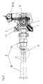
- the device for center reset 1 for by means of a clutch shaft 2 pivotally attached to a rail vehicle center buffer coupling a the pivoting movement of the coupling shaft 2 about its vertical pivot axis interactive guide 3, which is symmetrical to the longitudinal axis of the coupling shaft 2 arranged printing areas 4.
- the clutch shaft 2 is articulated by means of a vertically aligned bearing pin 6 in a link housing 5 and connected to the rail vehicle.
- the guide 3 is designed as a cam 3a, which is arranged by means of vertically Bolt 8 is rotatably mounted in the articulation housing 5.
- the cam plate 3a is coupled to the clutch shaft 2 in a rotationally synchronous manner, and the pin 8 is axially aligned with the bearing pin 6 of the coupling shaft 2 arranged.
- the bolt 8 is operatively connected to the bearing pin 6, and the Cam 3a is fixedly arranged with one below cam 3a Gear 9 connected, which via a gear 10 with an actuator 11, in particular connected and driven by an electric motor 11a.
- the printing device 7 is permanently active in the device 1 or Depending on the swivel angle, it can be switched off or switched off or by a pneumatically, hydraulically or electrically operated actuating means can be actuated is.
- the actuating means can be operated remotely Actuator 11 formed, with the help of the guide 3 or the cam 3a and the coupling shaft 2 operatively connected to it, coupled in any position of the intended horizontal swivel range of the coupling shaft (2) positionable in the power flow via the device 1 for center reset is.
- the coupling shaft 2 is in the embodiment by a rear shaft part 2a and a front shaft part 2b formed by means of joint 12 with vertical Pivot axis are connected and the front shaft part 2b against the rear Shaft part 2a is horizontally pivotable.
Landscapes
- Engineering & Computer Science (AREA)
- Mechanical Engineering (AREA)
- Transmission Devices (AREA)
- Vehicle Body Suspensions (AREA)
- Automobile Manufacture Line, Endless Track Vehicle, Trailer (AREA)
- Paper (AREA)
- Portable Nailing Machines And Staplers (AREA)
- Control Of Steam Boilers And Waste-Gas Boilers (AREA)
- Mechanical Operated Clutches (AREA)
Abstract
Description
- Fig. 1
- eine Seitenansicht der Vorrichtung zur Mittenrückstellung in teilgeschnittener Darstellung und
- Fig. 2
- eine Draufsicht auf die Vorrichtung zur Mittenrückstellung gemäß Fig.1.
- 1
- Mittenrückstellung
- 2
- Kupplungsschaft
- 2a
- hinteres Schaftteil
- 2b
- vorderes Schaftteil
- 3
- Führung
- 3a
- Kurvenscheibe
- 4
- Druckfläche
- 5
- Anlenkgehäuse
- 6
- Lagerbolzen
- 7
- Druckeinrichtung
- 8
- Bolzen
- 9
- Zahnrad
- 10
- Getriebe
- 11
- Stellantrieb
- 11a
- Elektromotor
- 12
- Gelenk
Claims (9)
- Vorrichtung zur horizontalen Mittenrückstellung (1) für eine mittels eines Kupplungsschafts (2) schwenkbar an einem Schienenfahrzeug angebrachten Mittelpufferkupplung mit einer die Schwenkbewegung des Kupplungsschafts (2) um seine vertikale Schwenkachse mitmachenden Führung (3), mit symmetrisch zur Längsachse des Kupplungsschafts (2) vorgesehenen Druckflächen (4) und mit gegenüber einem Anlenkgehäuse (5) für den Kupplungsschaft (2) abgestützten; die horizontale Mittenrückstellung bewirkenden Druckeinrichtungen (7), wobei jeder Druckfläche (4) eine der Druckeinrichtungen (7) zugeordnet ist, welche permanent wirkend oder schwenkwinkelabhängig abschaltend oder abschaltbar ausgebildet oder durch ein pneumatisch, hydraulisch oder elektrisch betriebenes Betätigungsmittel betägigbar sind, dadurch gekennzeichnet, dass das Betätigungsmittel als fernbedienbarer Stellantrieb (11) ausgebildet ist und dass die Führung (3) und damit der mit dieser wirkverbundene Kupplungsschaft (2) im Kraftfluss über die Vorrichtung (1) zur Mittenrückstellung in jede Stellung des vorgesehenen horizontalen Schwenkbereichs des Kupplungsschafts (2) mit Hilfe des Stellantriebes (11) positionierbar ist.
- Vorrichtung nach Anspruch 1, dadurch gekennzeichnet, dass die Führung (3) als Kurvenscheibe (3a) ausgebildet ist, die mittels vertikal angeordnetem Bolzen (8) drehbar im Anlenkgehäuse (5) gelagert ist und die mit dem Kupplungsschaft (2) drehsynchron gekoppelt ist.
- Vorrichtung nach Anspruch 2, dadurch gekennzeichnet, dass der Bolzen (8) axial fluchtend zum Lagerbolzen (6) des Kupplungsschafts (2) angeordnet ist.
- Vorrichtung nach Anspruch 3, dadurch gekennzeichnet, dass der Bolzen (8) mit dem Lagerbolzen (6) wirkverbunden ist.
- Vorrichtung nach einem oder mehreren der vorhergehenden Ansprüche 2 bis 4, dadurch gekennzeichnet, dass die Führung (3) bzw. die Kurvenscheibe (3a) fest mit einem Zahnrad (9) verbunden, das über ein Getriebe (10) von dem Stellantrieb (11), insbesondere einem Elektromotor (11a) antreibbar ist.
- Vorrichtung nach einem oder mehreren der vorhergehenden Ansprüche 1 bis 5, dadurch gekennzeichnet, dass im Bereich einer seitlichen Endlage des Kupplungsschafts (2) bzw. der Mittelpufferkupplung eine Einrichtung vorgesehen ist, die den Stellantrieb (11) nach Erreichen der Endlage selbsttätig abschaltet.
- Vorrichtung nach einem oder mehreren der vorhergehenden Ansprüche 1 bis 6, dadurch gekennzeichnet, dass der Kupplungsschaft (2)durch ein hinteres und ein vorderes Schaftteil (2a und 2b) gebildet ist, die mittels Gelenk (12) mit vertikaler Schwenkachse verbunden sind, wobei das vordere Schaftteil (2b) gegen das hintere Schaftteil (2a) horizontal verschwenkbar ausgebildet ist.
- Vorrichtung nach Anspruch 7, dadurch gekennzeichnet, dass im Bereich einer seitlichen Endlage des Kupplungsschafts (2) bzw. der Mittelpufferkupplung eine Einrichtung angeordnet ist, die den Schwenkvorgang des vorderen Schaftteils (2b) einleitet.
- Vorrichtung nach einem oder mehreren der vorhergehenden Ansprüche 1 bis 8, dadurch gekennzeichnet, dass die Schwenkvorgänge (Verschwenken des gestreckten Kupplungsschafts (2) aus der Mittenlage in eine seitliche Endlage und umgekehrt und/oder das Verschwenken des vorderen Schaftteils (2b)) automatisiert oder fernbetätigbar vorgesehen sind.
Applications Claiming Priority (2)
| Application Number | Priority Date | Filing Date | Title |
|---|---|---|---|
| DE10162731 | 2001-12-20 | ||
| DE10162731A DE10162731A1 (de) | 2001-12-20 | 2001-12-20 | Vorrichtung zur horizontalen Mittenrückstellung für eine mittels eines Kupplungsschafts schwenkbar an einem Schienenfahrzeug angebrachte Mittelpufferkupplung |
Publications (2)
| Publication Number | Publication Date |
|---|---|
| EP1321344A1 true EP1321344A1 (de) | 2003-06-25 |
| EP1321344B1 EP1321344B1 (de) | 2005-02-09 |
Family
ID=7710019
Family Applications (1)
| Application Number | Title | Priority Date | Filing Date |
|---|---|---|---|
| EP02027443A Expired - Lifetime EP1321344B1 (de) | 2001-12-20 | 2002-12-10 | Vorrichtung zur horizontalen Mittenrückstellung oder seitlichen Einstellung für eine Mittelpufferkupplung eines Schienenfahrzeuges |
Country Status (7)
| Country | Link |
|---|---|
| US (1) | US6805251B2 (de) |
| EP (1) | EP1321344B1 (de) |
| AT (1) | ATE288846T1 (de) |
| AU (1) | AU2002323892B2 (de) |
| DE (2) | DE10162731A1 (de) |
| ES (1) | ES2237648T3 (de) |
| PL (1) | PL194946B1 (de) |
Cited By (3)
| Publication number | Priority date | Publication date | Assignee | Title |
|---|---|---|---|---|
| EP1719686A1 (de) | 2005-05-06 | 2006-11-08 | Voith Turbo Scharfenberg GmbH & Co. KG | Trennbare Mittenstellungskupplung |
| DE102014101986A1 (de) | 2014-02-17 | 2015-08-20 | Voith Patent Gmbh | Kupplungsvorrichtung für einen Wagenkasten mit einem über ein Laufwerksystem geführten Fahrzeughauptrahmen |
| AT516914A1 (de) * | 2015-02-16 | 2016-09-15 | Siemens Ag Oesterreich | Verfahren und Einrichtung zur Zentrierung einer ungekuppelten Mittelpufferkupplung |
Families Citing this family (11)
| Publication number | Priority date | Publication date | Assignee | Title |
|---|---|---|---|---|
| DE10355640B3 (de) * | 2003-11-28 | 2004-11-04 | Voith Turbo Scharfenberg Gmbh & Co. Kg | Mittelpufferkupplung für Schienenfahrzeuge |
| PT1538057E (pt) * | 2003-12-05 | 2006-06-30 | Voith Turbo Scharfenberg Gmbh | Engate com tampao central com dispositivo de reposicao central |
| DK1719684T3 (da) * | 2005-05-03 | 2007-11-12 | Voith Turbo Scharfenberg Gmbh | Centralbufferkobling for skinnemonterede köretöjer |
| ES2334170T3 (es) * | 2007-04-25 | 2010-03-05 | Voith Patent Gmbh | Acoplamiento automatico articulado. |
| DE102010019905A1 (de) | 2010-05-05 | 2011-11-10 | Bombardier Transportation Gmbh | Kupplung von Schienenfahrzeugen, insbesondere zum Bergen eines nicht aus eigener Kraft fahrfähigen Schienenfahrzeugs |
| US9758182B2 (en) * | 2013-03-22 | 2017-09-12 | Wabtec Holding Corp. | Automated coupler positioning device |
| US9637146B2 (en) | 2013-05-22 | 2017-05-02 | Kawasaki Jukogyo Kabushiki Kaisha | Coupler system and railcar |
| US9701323B2 (en) | 2015-04-06 | 2017-07-11 | Bedloe Industries Llc | Railcar coupler |
| ITUB20154755A1 (it) * | 2015-11-05 | 2017-05-05 | Co El Da Software Srl | Sistema automatico di aggancio e sgancio di mezzi circolanti sulla rete ferroviaria |
| DE102018114745A1 (de) | 2018-06-20 | 2019-12-24 | Voith Patent Gmbh | Horizontale Mittenrückstellung für eine Mittelpufferkupplung |
| CN111497889B (zh) * | 2020-05-28 | 2025-03-21 | 中车制动系统有限公司 | 一种车钩自动对中装置及其组装方法 |
Citations (5)
| Publication number | Priority date | Publication date | Assignee | Title |
|---|---|---|---|---|
| US3484000A (en) * | 1966-05-18 | 1969-12-16 | Dresser Ind | Coupler positioning device |
| US3520421A (en) * | 1966-06-03 | 1970-07-14 | Pullman Inc | Coupler positioning arrangement for railway vehicles |
| US3627144A (en) * | 1970-06-08 | 1971-12-14 | Amsted Ind Inc | Coupler-positioning device |
| DE2822104A1 (de) * | 1974-04-20 | 1979-11-22 | Scharfenbergkupplung Gmbh | Horizontale mittenrueckstellung fuer eine selbsttaetige mittelpufferkupplung |
| DE19526504C1 (de) * | 1995-07-20 | 1996-07-25 | Bergische Stahlindustrie | Mittelpufferkupplung für Schienenfahrzeuge |
Family Cites Families (12)
| Publication number | Priority date | Publication date | Assignee | Title |
|---|---|---|---|---|
| US3498475A (en) * | 1966-01-07 | 1970-03-03 | Dresser Ind | Automatic hydraulic centering device |
| US3445005A (en) * | 1966-07-05 | 1969-05-20 | Amsted Ind Inc | Coupler centering device |
| US3587870A (en) * | 1968-02-06 | 1971-06-28 | Dresser Ind | Automatic hydraulic-mechanical coupler positioning device |
| DE1810593C3 (de) * | 1968-11-23 | 1981-12-24 | Bergische Stahl-Industrie, 5630 Remscheid | Vorrichtung zur horizontalen Mittenrückstellung einer an einem Fahrzeug angebrachten Mittelkupplung |
| US3788493A (en) * | 1971-10-26 | 1974-01-29 | Keystone Ind Inc | Coupler centering draft gear |
| DE2419184C3 (de) * | 1974-04-20 | 1980-05-29 | Scharfenbergkupplung Gmbh, 3320 Salzgitter | Vorrichtung zur horizontalen Mittenrückstellung einer Mittelpufferkupplung |
| DE2445460C2 (de) * | 1974-09-24 | 1982-09-23 | Bergische Stahl-Industrie, 5630 Remscheid | Vorrichtung zur Mittenrückstellung von Mittenrückstellung einer Mittelkupplun für Schienenfahrzeuge |
| DE3213697A1 (de) * | 1982-04-14 | 1983-10-20 | Scharfenbergkupplung Gmbh, 3320 Salzgitter | Mittelpufferkupplung fuer schienenfahrzeuge |
| US4569455A (en) * | 1984-04-04 | 1986-02-11 | Harvey Hubbell Incorporated | Centering detent |
| US4586620A (en) * | 1984-04-23 | 1986-05-06 | Andrews Russell J | Railroad car coupler alignment device |
| DE4328811C1 (de) * | 1993-08-27 | 1994-10-27 | Scharfenbergkupplung Gmbh | Mittelpufferkupplung für Schienenfahrzeuge |
| DE19513386A1 (de) * | 1995-04-08 | 1996-10-10 | Scharfenbergkupplung Gmbh | Längenverstellbare Kupplungsstange |
-
2001
- 2001-12-20 DE DE10162731A patent/DE10162731A1/de not_active Withdrawn
-
2002
- 2002-12-10 EP EP02027443A patent/EP1321344B1/de not_active Expired - Lifetime
- 2002-12-10 ES ES02027443T patent/ES2237648T3/es not_active Expired - Lifetime
- 2002-12-10 DE DE50202205T patent/DE50202205D1/de not_active Expired - Lifetime
- 2002-12-10 AT AT02027443T patent/ATE288846T1/de active
- 2002-12-18 PL PL357851A patent/PL194946B1/pl unknown
- 2002-12-18 US US10/322,931 patent/US6805251B2/en not_active Expired - Lifetime
- 2002-12-19 AU AU2002323892A patent/AU2002323892B2/en not_active Ceased
Patent Citations (5)
| Publication number | Priority date | Publication date | Assignee | Title |
|---|---|---|---|---|
| US3484000A (en) * | 1966-05-18 | 1969-12-16 | Dresser Ind | Coupler positioning device |
| US3520421A (en) * | 1966-06-03 | 1970-07-14 | Pullman Inc | Coupler positioning arrangement for railway vehicles |
| US3627144A (en) * | 1970-06-08 | 1971-12-14 | Amsted Ind Inc | Coupler-positioning device |
| DE2822104A1 (de) * | 1974-04-20 | 1979-11-22 | Scharfenbergkupplung Gmbh | Horizontale mittenrueckstellung fuer eine selbsttaetige mittelpufferkupplung |
| DE19526504C1 (de) * | 1995-07-20 | 1996-07-25 | Bergische Stahlindustrie | Mittelpufferkupplung für Schienenfahrzeuge |
Cited By (4)
| Publication number | Priority date | Publication date | Assignee | Title |
|---|---|---|---|---|
| EP1719686A1 (de) | 2005-05-06 | 2006-11-08 | Voith Turbo Scharfenberg GmbH & Co. KG | Trennbare Mittenstellungskupplung |
| DE102014101986A1 (de) | 2014-02-17 | 2015-08-20 | Voith Patent Gmbh | Kupplungsvorrichtung für einen Wagenkasten mit einem über ein Laufwerksystem geführten Fahrzeughauptrahmen |
| WO2015121479A1 (de) * | 2014-02-17 | 2015-08-20 | Voith Patent Gmbh | Kupplungsvorrichtung für einen wagenkasten mit einem über ein laufwerksystem geführten fahrzeughauptrahmen |
| AT516914A1 (de) * | 2015-02-16 | 2016-09-15 | Siemens Ag Oesterreich | Verfahren und Einrichtung zur Zentrierung einer ungekuppelten Mittelpufferkupplung |
Also Published As
| Publication number | Publication date |
|---|---|
| US20030116519A1 (en) | 2003-06-26 |
| US6805251B2 (en) | 2004-10-19 |
| ATE288846T1 (de) | 2005-02-15 |
| ES2237648T3 (es) | 2005-08-01 |
| DE10162731A1 (de) | 2003-07-03 |
| PL194946B1 (pl) | 2007-07-31 |
| EP1321344B1 (de) | 2005-02-09 |
| DE50202205D1 (de) | 2005-03-17 |
| PL357851A1 (en) | 2003-06-30 |
| AU2002323892B2 (en) | 2008-05-01 |
Similar Documents
| Publication | Publication Date | Title |
|---|---|---|
| EP1321344B1 (de) | Vorrichtung zur horizontalen Mittenrückstellung oder seitlichen Einstellung für eine Mittelpufferkupplung eines Schienenfahrzeuges | |
| EP0536528A1 (de) | Vorrichtung zur Bewegung einer Schwenkschiebetür für Fahrzeuge zur Personenbeförderung, insbesondere Schienenfahrzeuge | |
| EP1538057B1 (de) | Mittelpufferkupplung mit Mittenrückstellung. | |
| DE202012100064U1 (de) | Vorrichtung zur horizontalen Mittenrückstellung | |
| AT401376B (de) | Kuppel- und entkuppeleinrichtung für eine elektrische kabelkupplung und eine mechanische mittelpufferkupplung | |
| EP0963688B1 (de) | Arbeitsmaschine | |
| AT401375B (de) | Kuppel- und entkuppeleinrichtung für eine elektrische kabelkupplung und eine mechanische mittelpufferkupplung für ein schienenfahrzeug | |
| EP0442265B1 (de) | Klemmvorrichtung für ein axial verschiebbares Stellglied zur Greiferumsteuerung an einem Greiferzylinder einer Bogenrotationsdruckmaschine | |
| DE20120581U1 (de) | Vorrichtung zur horizontalen Mittenrückstellung für eine mittels eines Kupplungsschafts schwenkbar an einem Schienenfahrzeug angebrachte Mittelpufferkupplung | |
| DE2445460C2 (de) | Vorrichtung zur Mittenrückstellung von Mittenrückstellung einer Mittelkupplun für Schienenfahrzeuge | |
| EP3105100A1 (de) | Kupplungskopf einer automatischen mittelpufferkupplung | |
| DE102009003832A1 (de) | Lenkbare Verbundlenker-Hinterachse | |
| DE69301651T2 (de) | Spannkopf | |
| DE2741290A1 (de) | Fernbedienbarer rueckblickspiegel | |
| DE4302329B4 (de) | Höhenverstelleinrichtung für Sitze, insbesondere Kraftfahrzeugsitze | |
| EP3488972A1 (de) | Schwenkvorrichtung | |
| EP4204276A1 (de) | Sperrvorrichtung und sperrverfahren für einen weichenantrieb sowie weichenantrieb | |
| DE4218372C1 (de) | Kupplung zur Verbindung eines feststehenden Rohres mit einem beweglichen Rohr oder Schlauch | |
| EP0665334A2 (de) | Fräsmaschine und Gelenk | |
| DE102007055890A1 (de) | Rakeleinrichtung | |
| WO2018233898A1 (de) | Kupplungskopf einer automatischen mittelpufferkupplung | |
| EP4717537A1 (de) | Ventilbetätigungsvorrichtung für einen druckluftanschluss an einer automatischen mittelpufferkupplung | |
| DE170733C (de) | ||
| EP1127768B1 (de) | Elektrische Kabelkupplung mit einer Verriegelungseinrichtung, für ein Schienenfahrzeug | |
| EP1952953B1 (de) | Handwerkzeug zum Bohren und/oder Schrauben |
Legal Events
| Date | Code | Title | Description |
|---|---|---|---|
| PUAI | Public reference made under article 153(3) epc to a published international application that has entered the european phase |
Free format text: ORIGINAL CODE: 0009012 |
|
| AK | Designated contracting states |
Designated state(s): AT BE BG CH CY CZ DE DK EE ES FI FR GB GR IE IT LI LU MC NL PT SE SI SK TR |
|
| AX | Request for extension of the european patent |
Extension state: AL LT LV MK RO |
|
| 17P | Request for examination filed |
Effective date: 20030819 |
|
| 17Q | First examination report despatched |
Effective date: 20031107 |
|
| AKX | Designation fees paid |
Designated state(s): AT BE BG CH CY CZ DE DK EE ES FI FR GB GR IE IT LI LU MC NL PT SE SI SK TR |
|
| GRAP | Despatch of communication of intention to grant a patent |
Free format text: ORIGINAL CODE: EPIDOSNIGR1 |
|
| GRAS | Grant fee paid |
Free format text: ORIGINAL CODE: EPIDOSNIGR3 |
|
| GRAA | (expected) grant |
Free format text: ORIGINAL CODE: 0009210 |
|
| AK | Designated contracting states |
Kind code of ref document: B1 Designated state(s): AT BE BG CH CY CZ DE DK EE ES FI FR GB GR IE IT LI LU MC NL PT SE SI SK TR |
|
| PG25 | Lapsed in a contracting state [announced via postgrant information from national office to epo] |
Ref country code: BG Free format text: LAPSE BECAUSE OF FAILURE TO SUBMIT A TRANSLATION OF THE DESCRIPTION OR TO PAY THE FEE WITHIN THE PRESCRIBED TIME-LIMIT Effective date: 20050209 Ref country code: FI Free format text: LAPSE BECAUSE OF FAILURE TO SUBMIT A TRANSLATION OF THE DESCRIPTION OR TO PAY THE FEE WITHIN THE PRESCRIBED TIME-LIMIT Effective date: 20050209 Ref country code: IE Free format text: LAPSE BECAUSE OF FAILURE TO SUBMIT A TRANSLATION OF THE DESCRIPTION OR TO PAY THE FEE WITHIN THE PRESCRIBED TIME-LIMIT Effective date: 20050209 Ref country code: TR Free format text: LAPSE BECAUSE OF FAILURE TO SUBMIT A TRANSLATION OF THE DESCRIPTION OR TO PAY THE FEE WITHIN THE PRESCRIBED TIME-LIMIT Effective date: 20050209 Ref country code: SK Free format text: LAPSE BECAUSE OF FAILURE TO SUBMIT A TRANSLATION OF THE DESCRIPTION OR TO PAY THE FEE WITHIN THE PRESCRIBED TIME-LIMIT Effective date: 20050209 Ref country code: CZ Free format text: LAPSE BECAUSE OF FAILURE TO SUBMIT A TRANSLATION OF THE DESCRIPTION OR TO PAY THE FEE WITHIN THE PRESCRIBED TIME-LIMIT Effective date: 20050209 Ref country code: SI Free format text: LAPSE BECAUSE OF FAILURE TO SUBMIT A TRANSLATION OF THE DESCRIPTION OR TO PAY THE FEE WITHIN THE PRESCRIBED TIME-LIMIT Effective date: 20050209 Ref country code: EE Free format text: LAPSE BECAUSE OF FAILURE TO SUBMIT A TRANSLATION OF THE DESCRIPTION OR TO PAY THE FEE WITHIN THE PRESCRIBED TIME-LIMIT Effective date: 20050209 |
|
| REG | Reference to a national code |
Ref country code: GB Ref legal event code: FG4D Free format text: NOT ENGLISH |
|
| REG | Reference to a national code |
Ref country code: CH Ref legal event code: EP |
|
| GBT | Gb: translation of ep patent filed (gb section 77(6)(a)/1977) |
Effective date: 20050209 |
|
| REG | Reference to a national code |
Ref country code: IE Ref legal event code: FG4D Free format text: GERMAN |
|
| REF | Corresponds to: |
Ref document number: 50202205 Country of ref document: DE Date of ref document: 20050317 Kind code of ref document: P |
|
| PG25 | Lapsed in a contracting state [announced via postgrant information from national office to epo] |
Ref country code: DK Free format text: LAPSE BECAUSE OF FAILURE TO SUBMIT A TRANSLATION OF THE DESCRIPTION OR TO PAY THE FEE WITHIN THE PRESCRIBED TIME-LIMIT Effective date: 20050509 Ref country code: GR Free format text: LAPSE BECAUSE OF FAILURE TO SUBMIT A TRANSLATION OF THE DESCRIPTION OR TO PAY THE FEE WITHIN THE PRESCRIBED TIME-LIMIT Effective date: 20050509 |
|
| REG | Reference to a national code |
Ref country code: SE Ref legal event code: TRGR |
|
| REG | Reference to a national code |
Ref country code: ES Ref legal event code: FG2A Ref document number: 2237648 Country of ref document: ES Kind code of ref document: T3 |
|
| REG | Reference to a national code |
Ref country code: IE Ref legal event code: FD4D |
|
| ET | Fr: translation filed | ||
| PG25 | Lapsed in a contracting state [announced via postgrant information from national office to epo] |
Ref country code: CY Free format text: LAPSE BECAUSE OF FAILURE TO SUBMIT A TRANSLATION OF THE DESCRIPTION OR TO PAY THE FEE WITHIN THE PRESCRIBED TIME-LIMIT Effective date: 20051210 |
|
| PLBE | No opposition filed within time limit |
Free format text: ORIGINAL CODE: 0009261 |
|
| STAA | Information on the status of an ep patent application or granted ep patent |
Free format text: STATUS: NO OPPOSITION FILED WITHIN TIME LIMIT |
|
| PG25 | Lapsed in a contracting state [announced via postgrant information from national office to epo] |
Ref country code: LU Free format text: LAPSE BECAUSE OF NON-PAYMENT OF DUE FEES Effective date: 20051231 Ref country code: MC Free format text: LAPSE BECAUSE OF NON-PAYMENT OF DUE FEES Effective date: 20051231 |
|
| 26N | No opposition filed |
Effective date: 20051110 |
|
| PG25 | Lapsed in a contracting state [announced via postgrant information from national office to epo] |
Ref country code: CH Free format text: LAPSE BECAUSE OF NON-PAYMENT OF DUE FEES Effective date: 20061231 Ref country code: LI Free format text: LAPSE BECAUSE OF NON-PAYMENT OF DUE FEES Effective date: 20061231 |
|
| REG | Reference to a national code |
Ref country code: CH Ref legal event code: PL |
|
| PG25 | Lapsed in a contracting state [announced via postgrant information from national office to epo] |
Ref country code: PT Free format text: LAPSE BECAUSE OF NON-PAYMENT OF DUE FEES Effective date: 20050709 |
|
| PGFP | Annual fee paid to national office [announced via postgrant information from national office to epo] |
Ref country code: AT Payment date: 20141222 Year of fee payment: 13 Ref country code: FR Payment date: 20141219 Year of fee payment: 13 Ref country code: NL Payment date: 20141219 Year of fee payment: 13 |
|
| PGFP | Annual fee paid to national office [announced via postgrant information from national office to epo] |
Ref country code: IT Payment date: 20141219 Year of fee payment: 13 |
|
| PGFP | Annual fee paid to national office [announced via postgrant information from national office to epo] |
Ref country code: BE Payment date: 20141219 Year of fee payment: 13 |
|
| PG25 | Lapsed in a contracting state [announced via postgrant information from national office to epo] |
Ref country code: BE Free format text: LAPSE BECAUSE OF NON-PAYMENT OF DUE FEES Effective date: 20151231 |
|
| REG | Reference to a national code |
Ref country code: AT Ref legal event code: MM01 Ref document number: 288846 Country of ref document: AT Kind code of ref document: T Effective date: 20151210 |
|
| REG | Reference to a national code |
Ref country code: NL Ref legal event code: MM Effective date: 20160101 |
|
| REG | Reference to a national code |
Ref country code: FR Ref legal event code: ST Effective date: 20160831 |
|
| PG25 | Lapsed in a contracting state [announced via postgrant information from national office to epo] |
Ref country code: NL Free format text: LAPSE BECAUSE OF NON-PAYMENT OF DUE FEES Effective date: 20160101 |
|
| PG25 | Lapsed in a contracting state [announced via postgrant information from national office to epo] |
Ref country code: FR Free format text: LAPSE BECAUSE OF NON-PAYMENT OF DUE FEES Effective date: 20151231 Ref country code: AT Free format text: LAPSE BECAUSE OF NON-PAYMENT OF DUE FEES Effective date: 20151210 |
|
| PG25 | Lapsed in a contracting state [announced via postgrant information from national office to epo] |
Ref country code: IT Free format text: LAPSE BECAUSE OF NON-PAYMENT OF DUE FEES Effective date: 20151210 |
|
| PGFP | Annual fee paid to national office [announced via postgrant information from national office to epo] |
Ref country code: GB Payment date: 20201223 Year of fee payment: 19 |
|
| REG | Reference to a national code |
Ref country code: ES Ref legal event code: PC2A Owner name: VOITH PATENT GMBH Effective date: 20210201 |
|
| REG | Reference to a national code |
Ref country code: GB Ref legal event code: 732E Free format text: REGISTERED BETWEEN 20210121 AND 20210127 |
|
| REG | Reference to a national code |
Ref country code: GB Ref legal event code: 732E Free format text: REGISTERED BETWEEN 20210128 AND 20210203 |
|
| REG | Reference to a national code |
Ref country code: DE Ref legal event code: R082 Ref document number: 50202205 Country of ref document: DE Ref country code: DE Ref legal event code: R081 Ref document number: 50202205 Country of ref document: DE Owner name: VOITH PATENT GMBH, DE Free format text: FORMER OWNER: VOITH TURBO SCHARFENBERG GMBH & CO. KG, 38239 SALZGITTER, DE |
|
| PGFP | Annual fee paid to national office [announced via postgrant information from national office to epo] |
Ref country code: ES Payment date: 20210219 Year of fee payment: 19 |
|
| PGFP | Annual fee paid to national office [announced via postgrant information from national office to epo] |
Ref country code: DE Payment date: 20211210 Year of fee payment: 20 Ref country code: SE Payment date: 20211221 Year of fee payment: 20 |
|
| GBPC | Gb: european patent ceased through non-payment of renewal fee |
Effective date: 20211210 |
|
| PG25 | Lapsed in a contracting state [announced via postgrant information from national office to epo] |
Ref country code: GB Free format text: LAPSE BECAUSE OF NON-PAYMENT OF DUE FEES Effective date: 20211210 |
|
| REG | Reference to a national code |
Ref country code: DE Ref legal event code: R071 Ref document number: 50202205 Country of ref document: DE |
|
| REG | Reference to a national code |
Ref country code: SE Ref legal event code: EUG |
|
| REG | Reference to a national code |
Ref country code: ES Ref legal event code: FD2A Effective date: 20230217 |
|
| PG25 | Lapsed in a contracting state [announced via postgrant information from national office to epo] |
Ref country code: ES Free format text: LAPSE BECAUSE OF NON-PAYMENT OF DUE FEES Effective date: 20211211 |