EP1321404A2 - Procédé et dispositif pour contrôler l'orientation et l'alignement de feuilles de papier individuelles passant sur un transporteur - Google Patents
Procédé et dispositif pour contrôler l'orientation et l'alignement de feuilles de papier individuelles passant sur un transporteur Download PDFInfo
- Publication number
- EP1321404A2 EP1321404A2 EP02028159A EP02028159A EP1321404A2 EP 1321404 A2 EP1321404 A2 EP 1321404A2 EP 02028159 A EP02028159 A EP 02028159A EP 02028159 A EP02028159 A EP 02028159A EP 1321404 A2 EP1321404 A2 EP 1321404A2
- Authority
- EP
- European Patent Office
- Prior art keywords
- sheet
- disks
- disk
- conveyor
- alignment
- Prior art date
- Legal status (The legal status is an assumption and is not a legal conclusion. Google has not performed a legal analysis and makes no representation as to the accuracy of the status listed.)
- Granted
Links
Images



Classifications
-
- B—PERFORMING OPERATIONS; TRANSPORTING
- B65—CONVEYING; PACKING; STORING; HANDLING THIN OR FILAMENTARY MATERIAL
- B65H—HANDLING THIN OR FILAMENTARY MATERIAL, e.g. SHEETS, WEBS, CABLES
- B65H9/00—Registering, e.g. orientating, articles; Devices therefor
- B65H9/002—Registering, e.g. orientating, articles; Devices therefor changing orientation of sheet by only controlling movement of the forwarding means, i.e. without the use of stop or register wall
-
- B—PERFORMING OPERATIONS; TRANSPORTING
- B65—CONVEYING; PACKING; STORING; HANDLING THIN OR FILAMENTARY MATERIAL
- B65H—HANDLING THIN OR FILAMENTARY MATERIAL, e.g. SHEETS, WEBS, CABLES
- B65H9/00—Registering, e.g. orientating, articles; Devices therefor
- B65H9/10—Pusher and like movable registers; Pusher or gripper devices which move articles into registered position
- B65H9/103—Pusher and like movable registers; Pusher or gripper devices which move articles into registered position acting by friction or suction on the article for pushing or pulling it into registered position, e.g. against a stop
-
- B—PERFORMING OPERATIONS; TRANSPORTING
- B65—CONVEYING; PACKING; STORING; HANDLING THIN OR FILAMENTARY MATERIAL
- B65H—HANDLING THIN OR FILAMENTARY MATERIAL, e.g. SHEETS, WEBS, CABLES
- B65H2301/00—Handling processes for sheets or webs
- B65H2301/30—Orientation, displacement, position of the handled material
- B65H2301/33—Modifying, selecting, changing orientation
- B65H2301/331—Skewing, correcting skew, i.e. changing slightly orientation of material
-
- B—PERFORMING OPERATIONS; TRANSPORTING
- B65—CONVEYING; PACKING; STORING; HANDLING THIN OR FILAMENTARY MATERIAL
- B65H—HANDLING THIN OR FILAMENTARY MATERIAL, e.g. SHEETS, WEBS, CABLES
- B65H2301/00—Handling processes for sheets or webs
- B65H2301/30—Orientation, displacement, position of the handled material
- B65H2301/34—Modifying, selecting, changing direction of displacement
- B65H2301/341—Modifying, selecting, changing direction of displacement without change of plane of displacement
-
- B—PERFORMING OPERATIONS; TRANSPORTING
- B65—CONVEYING; PACKING; STORING; HANDLING THIN OR FILAMENTARY MATERIAL
- B65H—HANDLING THIN OR FILAMENTARY MATERIAL, e.g. SHEETS, WEBS, CABLES
- B65H2301/00—Handling processes for sheets or webs
- B65H2301/30—Orientation, displacement, position of the handled material
- B65H2301/36—Positioning; Changing position
- B65H2301/361—Positioning; Changing position during displacement
-
- B—PERFORMING OPERATIONS; TRANSPORTING
- B65—CONVEYING; PACKING; STORING; HANDLING THIN OR FILAMENTARY MATERIAL
- B65H—HANDLING THIN OR FILAMENTARY MATERIAL, e.g. SHEETS, WEBS, CABLES
- B65H2404/00—Parts for transporting or guiding the handled material
- B65H2404/10—Rollers
- B65H2404/15—Roller assembly, particular roller arrangement
Definitions
- the present invention generally relates to the art of paper handling and, in particular, to a method and a device for controlling the orientation and alignment of individual sheets of paper passing on a conveyor.
- Sheets of paper that travel individually along a conveyor are usually required to have a predetermined alignment and orientation.
- the conveyor has an alignment rail that extends parallel to the direction of sheet travel and the sheets are driven on the conveyor with a major component in the general travel direction and a small component towards the alignment rail, thereby forcing the sheets to move into abutment with the rail.
- An alignment rail may also correct potential orientation errors of the sheets by slightly rotating the sheets in the course of the alignment process. With increasing speeds of sheet travel and with relatively light paper, however, there is a risk that the sheets are damaged by being forced into abutment on the alignment rail.
- such an alignment rail can only correct for relatively small errors of sheet alignment and orientation, and it can neither introduce a major offset of sheet travel with respect to an original sheet alignment, nor can it produce a 90° rotation of the sheets so as to change their orientation or direction of travel, in a wide range of paper weight and at high speeds of sheet travel.
- the present invention provides a method and a device for controlling the orientation and alignment of individual sheets of paper passing on a conveyor, wherein even large errors of sheet alignment and sheet orientation can be corrected reliably and without the risk of sheet damage in a wide range of paper weight and at high continuous speeds of sheet travel, and wherein optionally an offset of sheet travel with respect to an original sheet alignment can be introduced, or a 90° rotation of the sheets can be produced so as to change the orientation or direction of travel of the sheets.
- a method of controlling at least one of the orientation and alignment of individual sheets of paper travelling on a conveyor is provided.
- Each sheet passes over a pair of closely spaced rotating disks and the sheet is locally engaged with each disk in a limited contact area, and the contact areas between the sheet and each disk are varied so as to achieve a target orientation or alignment of the sheet.
- the point of contact should be such that, at the point of contact, the tangential speed component of the disk is parallel to the sheet travel direction on the conveyor section upstream from the disks. Also, the tangential speed component should be of the same value as the upstream travelling speed of the sheet.
- the sheet travel direction can be acted on by changing the points of engagement between the sheet and the disks to shift the sheet laterally, or the disks are driven at different speeds as a sheet passes to rotate the sheet. Both actions can be combined to change the travel direction and simultaneously to rotate the sheet, whereby both of the alignment and the orientation of the sheet are controlled.
- the sheet should be released from the rotating disks. Just prior to this moment of sheet transfer from the pair of rotating disks to the downstream conveyor section, the sheet should be engaged by the disks at locations where the tangential speed component has the same direction as the travel direction of the downstream conveyor section.
- the travel directions of the upstream and downstream conveyor sections can be the same or different from each other and even be perpendicular to each other, the proposed method being capable of producing a full 90° rotation of a sheet without having to slow-down the sheet travel speed upon passing over the rotating disks.
- the present invention also provides a device for controlling at least one of the orientation and alignment of individual sheets of paper travelling on a conveyor, which is particularly designed to perform the inventive method.
- the device comprises a pair of closely spaced rotating disks arranged on a sheet travel path between upstream and downstream sections of the conveyor.
- the device also comprises a pair of engagement members each associated with one of the disks to define a sheet passage gap where the sheet is locally clamped.
- the engagement members are each movable opposite a respective disk within a 90° sector of the disk defined between a radius parallel to and a radius perpendicular to the sheet travel direction.
- the engagement members are positioned in synchronism so that the sheet passing over the continuously rotating disks is driven by each sheet in the same direction, but the speed of rotation of the disks may be varied between the disks as the sheet passes so as to produce a rotation of the sheet.
- a plurality of selectively activatable engagement members can be arranged at regular intervals about the periphery of each disk, and only one of these engagement members will be active at a given time.
- An engagement member can be an idle roller mounted on a first end of a pivotal carrier arm the pivot axis of which is co-axial with the axis of rotation of the associated disk. If a plurality of idle rollers are provided for each rotating disk, they are mounted on a carrier disk arranged opposite a respective rotating disk, the carrier disk being co-axial with the rotating disk and the idle rollers being retractable.
- each rotating disk has a plurality of perforations distributed over its periphery, and a suction member is arranged on a side of the disk opposite a sheet facing side of the disk, the suction member being aligned with the perforations and movable about the axis of rotation of the disk within a 90° sector of the disk.
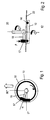
- a sheet handling unit includes a disk 10 that continuously rotates about an axis 12, although not necessarily at a constant speed of rotation.
- Disk 10 has an upper horizontal face that carries a plurality of closely spaced idle balls 14 aligned along the periphery of disk 10 to define a circular engagement track 16.
- Opposite engagement track 16 is an idle clamping roller 17 mounted on a free end of a horizontal carrier arm 18 the opposed end of which is attached to a shaft 20 that is co-axial with axis 12 of disk 10.
- Shaft 20 is connected to a rotary drive that can be controlled to pivot carrier arm 18 within a 90° sector so that it can assume any position within this sector.
- FIG. 1 illustrates a 90° position and an angle ⁇ position of carrier arm 18.
- the clamping roller 17 and the idle balls 14 define a gap where a sheet of paper 22 is locally clamped.
- a hollow arrow indicates the direction of sheet travel on a conveyor
- a solid arrow indicates the direction of rotation of disk 10.
- the 90° sector of sheet engagement is defined between axis 12, the direction of sheet travel and a line perpendicular to that direction.
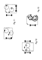
- Sheet travel control device B includes a pair of sheet handling units B 1 and B2 each of the kind shown in Figs. 1 and 2, although other embodiments could be envisioned.
- Units B1 and B2 are closely spaced from each other and aligned in a direction perpendicular to the general direction of sheet travel indicated by solid arrows in Fig. 3.
- rollers 17 of both units B1 and B2 are shown in a 0° position.
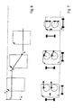
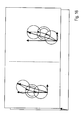
- Figs. 5 and 6 illustrate the typical successive steps of a complete offset generating procedure.
- the sheet is fully under control of the upstream conveyor section.
- the sheet is released from the upstream conveyor section and engaged by the sheet travel control device, which initially advances the sheet in the original travel direction.
- the sheet is moved in a direction inclined to the original travel direction.
- the idle rollers have been restored to the original 0° position, and the sheet is advanced to the downstream conveyor section, but with an offset "O" with respect to the original sheet alignment.
- each sheet is released from engagement with the device at the moment the sheet is engaged by the downstream conveyor section.
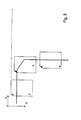
- Figs. 7 and 8 illustrate a scenario where the upstream and downstream conveyor sections are mutually perpendicular and the orientation of the sheet with respect to its travelling direction is changed by 90°.
- Steps 1, 2 and 3 are identical with those in Figs. 5 and 6.
- step 4 the idle rollers are pivoted to a full 90° position so that the sheet is advanced in a direction perpendicular to the original travel direction and identical with the travel direction on the downstream conveyor section, without having been rotated.
- both disks of the sheet travel control device are driven in the same direction of rotation, and the idle rollers assume identical angular positions.
- Fig. 9a and 9b show embodiments where the two discs are driven in opposite directions. In this case, the idle rollers must assume angular positions mutually shifted by 180°.
- both disks of the sheet travel control device are driven at identical speeds so that the orientation of the sheet remains unchanged.
- both disks are driven at different velocities, which can be varied as a sheet passes over the disks.
- a typical controller to effect this would include a microprocessor.
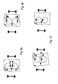
- one disk is driven at velocity V1 and the other at velocity V2, with V1 > V2, thereby producing a counter-clock rotation of the sheet.
- the positions of the idle rollers remain unchanged, unless an offset is to be generated in addition to a sheet rotation.
- both disks in the sheet travel control device are aligned perpendicular to the original direction of sheet travel.
- the disks are shifted with respect to each other in the direction of sheet travel. This is the preferred embodiment when a sheet rotation is to be combined with a change of sheet travel direction.
- a further embodiment depicted in Fig. 12 has both disks aligned in the direction of sheet ravel.
- each set of rollers is carried by a carrier in the shape of a carrier disk or a star and rotatable within a sector of 90° with respect to the associated rotating disk.
- the idle rollers are selectively retractable, and only one of them is advanced at a time to engage a passing sheet of paper.
- a sheet is locally engaged by a rotating disk in that it is mechanically clamped between the disk and a clamping roller.
- a sheet is pneumatically engaged by a rotating disk.
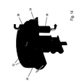
- a rotating disk 30 has multiple closely spaced perforations 32 along its periphery. The upper face of disk 30 is exposed to a sheet passing thereover.
- a suction register 34 presents an opening 34 of a suction channel 36 to the opposite face of disk 30 in alignment with the perforations 32. Suction register 34 is rotated within a sector of 90° with respect to disk 30, in a manner analogous to the clamping rollers in the above embodiments.
- a sheet is locally engaged with the upper face of disk 30 by pneumatic action, and the position of local engagement is controlled by virtue of controlling the angular position of suction register 34.
- pneumatic embodiment can be configured to operate in a manner analogous to the mechanical embodiments disclosed above, an even higher degree of flexibility and process control is achieved. This is illustrated by Figs. 15 and 16.
- a left-hand disk unit tends to deflect a passing sheet towards the left in a first step while a right-hand disk unit tends to deflect the sheet to the right by a like amount in the same step. Since both actions are opposed and of like magnitude, they cancel each other, but the sheet is under a strong constraint to advance in the original travel direction.
- the left-hand disk unit tends to deflect a passing sheet towards the right while a right-hand disk unit tends to deflect the sheet also to the right, but by a larger amount. Due to the differing amounts of deflection that both disks attempt to impose upon the sheet, a lateral offset with respect to the original sheet alignment is generated under a strong constraint, thereby combining a high alignment accuracy with a high process speed.
Landscapes
- Engineering & Computer Science (AREA)
- Mechanical Engineering (AREA)
- Registering Or Overturning Sheets (AREA)
- Delivering By Means Of Belts And Rollers (AREA)
Applications Claiming Priority (2)
| Application Number | Priority Date | Filing Date | Title |
|---|---|---|---|
| DE10163304 | 2001-12-21 | ||
| DE10163304 | 2001-12-21 |
Publications (3)
| Publication Number | Publication Date |
|---|---|
| EP1321404A2 true EP1321404A2 (fr) | 2003-06-25 |
| EP1321404A3 EP1321404A3 (fr) | 2005-01-12 |
| EP1321404B1 EP1321404B1 (fr) | 2009-03-25 |
Family
ID=7710399
Family Applications (1)
| Application Number | Title | Priority Date | Filing Date |
|---|---|---|---|
| EP02028159A Expired - Lifetime EP1321404B1 (fr) | 2001-12-21 | 2002-12-19 | Procédé et dispositif pour contrôler l'orientation et l'alignement de feuilles de papier individuelles passant sur un transporteur |
Country Status (3)
| Country | Link |
|---|---|
| US (1) | US6811152B2 (fr) |
| EP (1) | EP1321404B1 (fr) |
| DE (2) | DE60231695D1 (fr) |
Cited By (3)
| Publication number | Priority date | Publication date | Assignee | Title |
|---|---|---|---|---|
| WO2007106038A1 (fr) * | 2006-03-16 | 2007-09-20 | Plockmatic International Ab | Dispositif permettant de changer la position de feuilles de papier dans une chaine d'ecoulement ainsi que materiel pour la manipulation ulterieure des feuilles |
| US8875868B2 (en) | 2010-08-06 | 2014-11-04 | Ferag Ag | Apparatus for aligning a sheet product |
| WO2019072416A1 (fr) * | 2017-10-10 | 2019-04-18 | Bobst Grenchen Ag | Dispositif d'orientation de feuille, machine pour le traitement d'une feuille ainsi que procédé pour l'orientation d'une feuille |
Families Citing this family (13)
| Publication number | Priority date | Publication date | Assignee | Title |
|---|---|---|---|---|
| JP4350450B2 (ja) * | 2003-08-04 | 2009-10-21 | キヤノン株式会社 | シート搬送装置及び画像形成装置並びに画像読取装置 |
| US7648138B2 (en) * | 2004-09-14 | 2010-01-19 | Hitachi-Omron Terminal Solutions, Corp. | Sheet handling apparatus |
| US7416183B2 (en) * | 2005-06-06 | 2008-08-26 | Pitney Bowes Inc. | Postal weighing platform with integrated feeding and deskewing functions |
| US7636543B2 (en) * | 2005-11-30 | 2009-12-22 | Xerox Corporation | Radial merge module for printing system |
| US7669842B2 (en) * | 2006-08-22 | 2010-03-02 | Xerox Corporation | Sheet rotator |
| US20090152806A1 (en) * | 2007-12-17 | 2009-06-18 | Xerox Corporation | Sheet lateral positioning device |
| KR101132478B1 (ko) * | 2010-10-29 | 2012-03-30 | 엘지엔시스(주) | 매체이송장치 |
| US8523174B2 (en) * | 2011-02-18 | 2013-09-03 | Xerox Corporation | Media rotation and translation mechanism |
| US8348267B2 (en) | 2011-02-18 | 2013-01-08 | Xerox Corporation | Media rotation and translation apparatus |
| US8424873B2 (en) | 2011-04-06 | 2013-04-23 | Xerox Corporation | Magnetic coupled intermediate idler |
| RU2511233C2 (ru) * | 2011-12-23 | 2014-04-10 | Гизеке Унд Девриент Гмбх | Устройство для манипулирования листовым материалом и способ обработки листового материала |
| US9679229B2 (en) | 2015-09-25 | 2017-06-13 | Assa Abloy Ab | Credential production device card substrate rotator |
| WO2025165397A1 (fr) | 2024-01-29 | 2025-08-07 | Kohlam, Llc | Dispositif d'alignement de composite multicouche |
Family Cites Families (15)
| Publication number | Priority date | Publication date | Assignee | Title |
|---|---|---|---|---|
| GB376554A (en) * | 1930-09-29 | 1932-07-14 | Maschf Augsburg Nuernberg Ag | Improvements in or relating to registering devices for sheet feeding apparatus for printing machines |
| DE716124C (de) * | 1937-07-07 | 1942-01-14 | Brehmer Geb | Papierfoerdervorrichtung, insbesondere fuer Querfoerdertische von Stauchfalzmaschinen |
| US4165870A (en) * | 1978-03-20 | 1979-08-28 | International Business Machines Corporation | Wave generator to shingle sheets |
| JPS61217447A (ja) * | 1985-03-20 | 1986-09-27 | Toray Ind Inc | シ−ト状物の安定搬送装置 |
| DE3511897A1 (de) * | 1985-04-01 | 1986-10-09 | Mabeg Maschinenbau Gmbh Nachf. Hense & Pleines Gmbh & Co, 6050 Offenbach | Vorrichtung zum seitlichen ausrichten von bogen |
| FR2594065A1 (fr) * | 1986-02-11 | 1987-08-14 | Aaron Rene Ets | Dispositif de guidage automatique de materiaux deformables sous forme de feuilles |
| US4756521A (en) * | 1987-03-12 | 1988-07-12 | Pitney Bowes Inc. | Methods and apparatus for turning flat articles |
| US4927132A (en) * | 1988-07-28 | 1990-05-22 | Transtechnology Corporation | Document transport apparatus |
| US4928807A (en) * | 1988-12-02 | 1990-05-29 | Pitney Bowes Inc. | Method and apparatus for turning flat articles |
| FR2667052B3 (fr) * | 1990-09-26 | 1992-09-04 | Sepaic | Dispositif de guidage de materiau souple en forme de feuille. |
| DE4445443C2 (de) * | 1994-12-20 | 1998-07-09 | Heidelberger Druckmasch Ag | Vorrichtung zum Ausrichten von Bogen |
| US5692746A (en) * | 1995-08-08 | 1997-12-02 | Roll Systems, Inc. | Sheet rotator and justifier |
| US5915689A (en) * | 1997-08-19 | 1999-06-29 | Xerox Corporation | Quick change swiper blades |
| US6343686B1 (en) * | 2000-05-09 | 2002-02-05 | Xerox Corporation | Rotating clamp for changing the orientation of a substrate stack |
| JP4601792B2 (ja) * | 2000-09-14 | 2010-12-22 | 株式会社東芝 | 紙葉類処理装置 |
-
2002
- 2002-12-19 US US10/322,754 patent/US6811152B2/en not_active Expired - Lifetime
- 2002-12-19 DE DE60231695T patent/DE60231695D1/de not_active Expired - Lifetime
- 2002-12-19 EP EP02028159A patent/EP1321404B1/fr not_active Expired - Lifetime
- 2002-12-19 DE DE0001321404T patent/DE02028159T1/de active Pending
Cited By (6)
| Publication number | Priority date | Publication date | Assignee | Title |
|---|---|---|---|---|
| WO2007106038A1 (fr) * | 2006-03-16 | 2007-09-20 | Plockmatic International Ab | Dispositif permettant de changer la position de feuilles de papier dans une chaine d'ecoulement ainsi que materiel pour la manipulation ulterieure des feuilles |
| US8875868B2 (en) | 2010-08-06 | 2014-11-04 | Ferag Ag | Apparatus for aligning a sheet product |
| WO2019072416A1 (fr) * | 2017-10-10 | 2019-04-18 | Bobst Grenchen Ag | Dispositif d'orientation de feuille, machine pour le traitement d'une feuille ainsi que procédé pour l'orientation d'une feuille |
| CN111344239A (zh) * | 2017-10-10 | 2020-06-26 | 鲍勃斯脱格伦兴股份公司 | 片材对齐装置、加工片材的加工机、以及对齐片材的方法 |
| CN111344239B (zh) * | 2017-10-10 | 2021-11-02 | 鲍勃斯脱格伦兴股份公司 | 片材对齐装置、加工片材的加工机、以及对齐片材的方法 |
| US11447353B2 (en) | 2017-10-10 | 2022-09-20 | Bobst Grenchen Ag | Sheet orientation device, machine for processing a sheet, and method for orienting a sheet |
Also Published As
| Publication number | Publication date |
|---|---|
| EP1321404B1 (fr) | 2009-03-25 |
| DE02028159T1 (de) | 2004-04-15 |
| US6811152B2 (en) | 2004-11-02 |
| US20030146568A1 (en) | 2003-08-07 |
| EP1321404A3 (fr) | 2005-01-12 |
| DE60231695D1 (de) | 2009-05-07 |
Similar Documents
| Publication | Publication Date | Title |
|---|---|---|
| US6811152B2 (en) | Method and device for controlling the orientation and alignment of individual sheets of paper passing on a conveyor | |
| JP5140603B2 (ja) | 物品の方向転換システム及び方法 | |
| US7975584B2 (en) | Single transfer insert placement method and apparatus | |
| EP1820757B1 (fr) | Appareil de transfert et de mise en place d'article et curseur actif | |
| US9950439B2 (en) | Single transfer insert placement method and apparatus with cross-direction insert placement control | |
| JP3755959B2 (ja) | ローラコンベア上でシートを旋回する装置 | |
| CA2473821C (fr) | Appareil permettant la rotation d'un article | |
| US6550656B2 (en) | Device for spreading, compressing and guiding a running material web | |
| EP1355840B1 (fr) | Unite de guidage pour bande transporteuse | |
| JP2009504541A (ja) | 改良されたタイミングコンベヤを与えるシステム及び方法 | |
| AU2002226814A1 (en) | Guidance unit for conveyor belt | |
| JPH08192948A (ja) | 製品の搬送方向を変更する装置 | |
| US5131937A (en) | Device for aligning glazing panes during transport on a roller conveyor | |
| CN111107815A (zh) | 用于施加吸收性物品的部段的设备 | |
| US4413723A (en) | Method and apparatus for conveying a sheet | |
| US5109975A (en) | Segmented turning device | |
| WO2021044728A1 (fr) | Équipement à ramification | |
| JP6867173B2 (ja) | 搬送装置 | |
| US4068838A (en) | Conveyor and three-roller sheet deflector for sheet distributor | |
| JP2750528B2 (ja) | 単板の切断装置 | |
| JP2536909Y2 (ja) | 仕分装置 | |
| JPH10120154A (ja) | 回収びん等の搬送流れ制御装置 | |
| US20240034567A1 (en) | Angled transfer with roller chain | |
| JP5800723B2 (ja) | 媒体の回転移動機構 | |
| JP2006335570A (ja) | シートを処理する機械にシートを搬送する方法および装置 |
Legal Events
| Date | Code | Title | Description |
|---|---|---|---|
| PUAI | Public reference made under article 153(3) epc to a published international application that has entered the european phase |
Free format text: ORIGINAL CODE: 0009012 |
|
| AK | Designated contracting states |
Designated state(s): AT BE BG CH CY CZ DE DK EE ES FI FR GB GR IE IT LI LU MC NL PT SE SI SK TR |
|
| AX | Request for extension of the european patent |
Extension state: AL LT LV MK RO |
|
| EL | Fr: translation of claims filed | ||
| DET | De: translation of patent claims | ||
| PUAL | Search report despatched |
Free format text: ORIGINAL CODE: 0009013 |
|
| AK | Designated contracting states |
Kind code of ref document: A3 Designated state(s): AT BE BG CH CY CZ DE DK EE ES FI FR GB GR IE IT LI LU MC NL PT SE SI SK TR |
|
| AX | Request for extension of the european patent |
Extension state: AL LT LV MK RO |
|
| 17P | Request for examination filed |
Effective date: 20050411 |
|
| AKX | Designation fees paid |
Designated state(s): DE FR GB IT |
|
| 17Q | First examination report despatched |
Effective date: 20050822 |
|
| GRAP | Despatch of communication of intention to grant a patent |
Free format text: ORIGINAL CODE: EPIDOSNIGR1 |
|
| RAP1 | Party data changed (applicant data changed or rights of an application transferred) |
Owner name: C.P. BOURG S.A. |
|
| GRAS | Grant fee paid |
Free format text: ORIGINAL CODE: EPIDOSNIGR3 |
|
| GRAA | (expected) grant |
Free format text: ORIGINAL CODE: 0009210 |
|
| AK | Designated contracting states |
Kind code of ref document: B1 Designated state(s): DE FR GB IT |
|
| REG | Reference to a national code |
Ref country code: GB Ref legal event code: FG4D |
|
| REF | Corresponds to: |
Ref document number: 60231695 Country of ref document: DE Date of ref document: 20090507 Kind code of ref document: P |
|
| PLBE | No opposition filed within time limit |
Free format text: ORIGINAL CODE: 0009261 |
|
| STAA | Information on the status of an ep patent application or granted ep patent |
Free format text: STATUS: NO OPPOSITION FILED WITHIN TIME LIMIT |
|
| 26N | No opposition filed |
Effective date: 20091229 |
|
| REG | Reference to a national code |
Ref country code: FR Ref legal event code: PLFP Year of fee payment: 14 |
|
| REG | Reference to a national code |
Ref country code: FR Ref legal event code: ST Effective date: 20170831 |
|
| REG | Reference to a national code |
Ref country code: FR Ref legal event code: PLFP Year of fee payment: 16 |
|
| PG25 | Lapsed in a contracting state [announced via postgrant information from national office to epo] |
Ref country code: FR Free format text: LAPSE BECAUSE OF NON-PAYMENT OF DUE FEES Effective date: 20170102 |
|
| REG | Reference to a national code |
Ref country code: FR Ref legal event code: RN Effective date: 20171128 |
|
| REG | Reference to a national code |
Ref country code: FR Ref legal event code: FC Effective date: 20180124 |
|
| PG25 | Lapsed in a contracting state [announced via postgrant information from national office to epo] |
Ref country code: FR Free format text: LAPSE BECAUSE OF NON-PAYMENT OF DUE FEES Effective date: 20170102 |
|
| PGRI | Patent reinstated in contracting state [announced from national office to epo] |
Ref country code: FR Effective date: 20180124 |
|
| REG | Reference to a national code |
Ref country code: FR Ref legal event code: PLFP Year of fee payment: 17 |
|
| PGFP | Annual fee paid to national office [announced via postgrant information from national office to epo] |
Ref country code: FR Payment date: 20201221 Year of fee payment: 19 Ref country code: GB Payment date: 20201218 Year of fee payment: 19 |
|
| PGFP | Annual fee paid to national office [announced via postgrant information from national office to epo] |
Ref country code: IT Payment date: 20201218 Year of fee payment: 19 |
|
| PGFP | Annual fee paid to national office [announced via postgrant information from national office to epo] |
Ref country code: DE Payment date: 20201231 Year of fee payment: 19 |
|
| REG | Reference to a national code |
Ref country code: DE Ref legal event code: R119 Ref document number: 60231695 Country of ref document: DE |
|
| GBPC | Gb: european patent ceased through non-payment of renewal fee |
Effective date: 20211219 |
|
| PG25 | Lapsed in a contracting state [announced via postgrant information from national office to epo] |
Ref country code: GB Free format text: LAPSE BECAUSE OF NON-PAYMENT OF DUE FEES Effective date: 20211219 Ref country code: DE Free format text: LAPSE BECAUSE OF NON-PAYMENT OF DUE FEES Effective date: 20220701 |
|
| PG25 | Lapsed in a contracting state [announced via postgrant information from national office to epo] |
Ref country code: FR Free format text: LAPSE BECAUSE OF NON-PAYMENT OF DUE FEES Effective date: 20211231 |
|
| PG25 | Lapsed in a contracting state [announced via postgrant information from national office to epo] |
Ref country code: IT Free format text: LAPSE BECAUSE OF NON-PAYMENT OF DUE FEES Effective date: 20211219 |