EP1321579A1 - Coffrage de revêtement de sol et procédé pour la construction d'un tel revêtement de sol - Google Patents
Coffrage de revêtement de sol et procédé pour la construction d'un tel revêtement de sol Download PDFInfo
- Publication number
- EP1321579A1 EP1321579A1 EP02028339A EP02028339A EP1321579A1 EP 1321579 A1 EP1321579 A1 EP 1321579A1 EP 02028339 A EP02028339 A EP 02028339A EP 02028339 A EP02028339 A EP 02028339A EP 1321579 A1 EP1321579 A1 EP 1321579A1
- Authority
- EP
- European Patent Office
- Prior art keywords
- mold
- walls
- grid
- molded
- wall
- Prior art date
- Legal status (The legal status is an assumption and is not a legal conclusion. Google has not performed a legal analysis and makes no representation as to the accuracy of the status listed.)
- Withdrawn
Links
Images



Classifications
-
- B—PERFORMING OPERATIONS; TRANSPORTING
- B28—WORKING CEMENT, CLAY, OR STONE
- B28B—SHAPING CLAY OR OTHER CERAMIC COMPOSITIONS; SHAPING SLAG; SHAPING MIXTURES CONTAINING CEMENTITIOUS MATERIAL, e.g. PLASTER
- B28B7/00—Moulds; Cores; Mandrels
- B28B7/34—Moulds, cores, or mandrels of special material, e.g. destructible materials
- B28B7/342—Moulds, cores, or mandrels of special material, e.g. destructible materials which are at least partially destroyed, e.g. broken, molten, before demoulding; Moulding surfaces or spaces shaped by, or in, the ground, or sand or soil, whether bound or not; Cores consisting at least mainly of sand or soil, whether bound or not
-
- B—PERFORMING OPERATIONS; TRANSPORTING
- B28—WORKING CEMENT, CLAY, OR STONE
- B28B—SHAPING CLAY OR OTHER CERAMIC COMPOSITIONS; SHAPING SLAG; SHAPING MIXTURES CONTAINING CEMENTITIOUS MATERIAL, e.g. PLASTER
- B28B7/00—Moulds; Cores; Mandrels
- B28B7/24—Unitary mould structures with a plurality of moulding spaces, e.g. moulds divided into multiple moulding spaces by integratable partitions, mould part structures providing a number of moulding spaces in mutual co-operation
- B28B7/241—Detachable assemblies of mould parts providing only in mutual co-operation a number of complete moulding spaces
-
- E—FIXED CONSTRUCTIONS
- E01—CONSTRUCTION OF ROADS, RAILWAYS, OR BRIDGES
- E01C—CONSTRUCTION OF, OR SURFACES FOR, ROADS, SPORTS GROUNDS, OR THE LIKE; MACHINES OR AUXILIARY TOOLS FOR CONSTRUCTION OR REPAIR
- E01C9/00—Special pavings; Pavings for special parts of roads or airfields
- E01C9/001—Paving elements formed in situ; Permanent shutterings therefor ; Inlays or reinforcements which divide the cast material in a great number of individual units
Definitions
- the invention relates to a mold and a method for manufacturing at least one shaped stone and one made from it Band Aid.
- molded blocks are made by pouring made of concrete in a bottomed form.
- the shape is made of a material like metal or wood, which has a long service life and is as simple as possible Cleaning guaranteed.
- the shaped stones are packed and sent to the customer transported.
- the surface is first compacted. Then one is usually made of sand or fine gravel Compensating layer applied. Then be on the stones laid. After laying the They are shaped stones to ensure a good fit shaken by means of a vibrating machine. The joints are then filled with sand.
- the object of the invention is to overcome the disadvantages of the prior art of technology to eliminate.
- it should have a shape and a method are specified with which a simplified Production of shaped stones is possible.
- Another goal the invention is a simplified manufacture of a Plaster to be specified using the form.
- a mold for production is at least a shaped stone formed from a potting compound provided with at least a first mold wall and at least a second mold wall, the first and the second Molded wall with one another by means of a plug-in, adhesive or snap-in connection to train at least one by rotating Molded walls limited individual shape can be connected.
- first and second mold walls which are Adhesive or snap-in connection can be connected to one another easy transportation and space-saving storage. The shape allows the shaped stone to be produced at the destination.
- a form for producing a plurality of formed from a potting compound and shaped stones arranged in the manner of a plaster provided comprising a plurality of circumferential mold walls limited individual forms that by means of a plug-in, adhesive or Snap connection can be connected to each other.
- the individual forms consist of circumferential ones Mold walls.
- the bottom of the individual forms is open.
- the individual forms are expediently formed in one piece. she can e.g. B. made of injection molded plastic his. It may also be that several individual forms form one grid or grid-like shaped element are connected.
- the shaped elements are by means of their peripheral ones Molded plug, adhesive or snap connection provided connectable with each other.
- Such shaped elements can, for. B. for Manufactured each from one square meter of plaster his. With such shaped elements, the shape can be special time-saving installation on the spot. With the The shaped stones forming the pavement can shape at the destination getting produced.
- the proposed shapes can be Adhesive or snap connections are connected to each other.
- Such plug or snap connections are according to the state of the Technology well known. It can be z. B. slots act and corresponding T-profiles, which at the External wall of the individual molds are provided. For connection the T-profiles can be inserted into the slots. Likewise, pins can be provided, which correspond to Openings of the other individual form or Intervene formulas. It is also conceivable, for example a double-sided adhesive tape on the outside of the individual molds or attach form elements so that they are together can be glued. In particular plug or snap connections can be easily made from plastic Individual shapes or form elements can be realized.
- the invention Form no or at least not a completely closed one Ground on. As a result, it flows into the form a pouring compound poured onto the substrate.
- the hardened stone lies positively on the Underground on.
- the shape can be put into place with little effort be transported on which a plaster is laid should. It enables the production of the plaster to be made Form stones at the place of installation. It does not apply to the after State of the art required cumbersome and costly Logistics of the production of a shaped or paving stone in a concrete plant and the transport to the installation site.
- Another advantage is that using the proposed form by the customer exactly the amount of Shaped stones can be made, which actually needed becomes. The shape can be changed with little effort. This makes it unnecessary to cut prefabricated stones or break.
- the mold walls have Folds to make bends. This allows simply adapt the shape to the respective requirements.
- the mold walls are advantageously at least in sections from a rotten organic material, from plastic or made of metal.
- the mold walls can essentially from paper raw materials, cardboard, cardboard, corrugated cardboard, Be made of polystyrene or polyethylene.
- Under rotten Material is also plastic, such as polyethylene, understood that rots relatively slowly.
- the form e.g. is made of corrugated cardboard, it is only for suitable for one-time casting. As a result of the encapsulation, this disappears paper material used to make the mold on and rots quickly. It is not necessary to shape it remove.
- the mold walls expediently have slots or openings on so that they can be plugged together like a grid are.
- the first mold walls have slots on their an opening area for pouring facing first edges and the second mold walls have slots on their first edges have opposite second edges.
- the slots usually run vertically and are half the height of the mold walls. So you can easily plug into each other a grid is produced for the first and second mold walls become.
- the grid is mated Condition so a lot by circulating Molded walls limited to individual shapes.
- the grid can go through bounded at least one arch-shaped mold wall his.
- Such a grid is suitable e.g. excellent for Formation of curves on sidewalks. But it is also possible Using traffic signs, company logos and the like the shape of the invention in a simple manner on site in shape of a patch.
- the individual shapes can each be square, rectangular, have hexagonal or octagonal or round opening areas. Of course, it is also possible to use the opening areas run in a different geometry.
- By means of the proposed Sections of a shape can be easily created Patches are made. It can be done with little effort Patterns or advertisements can be provided in the pavement.
- the mold walls are double-walled educated.
- the two walls are through with each other vertical webs connected to each other.
- So trained Molded walls are particularly dimensionally stable. You can e.g. B. from Plastic can be produced by extrusion.
- the shape in the case of molded walls made of corrugated cardboard, the shape is so is formed that the apex lines of the corrugation are perpendicular are aligned with the opening area. This allows it, from the opening area sand into the cavity of the corrugated cardboard technicallyrieseln.
- the first facing the opening surface Edges of the mold walls are designed as a bend. The Bending has the purpose of penetrating the casting compound into the cavities of e.g. Molded walls made from corrugated cardboard to prevent. There will be a separation of the stones guaranteed. The shaped stones can be replaced after hardening become.
- a perforation and / or a Means are provided to tear open the mold wall along the bend his.
- the tearing agent can e.g. around one worked into the mold wall along the bend Trade cord. This allows the mold wall in the area the first edges after potting. An intrusion of water and / or sand is then easily possible. The The rotting of the mold and the filling of the joints are accelerated.
- the bend can be in the form of a triangle in cross section be formed and a substantially parallel to the opening area have trained peel surface.
- Cross-section bending in the manner of a triangle the top edges are one using one Form beveled shaped stone. That makes it easier filling the joints. It also increases the risk of injury reduced when changing the stones.
- one can be based on the first Edges attachable profile can be provided.
- the profile is expediently a, preferably made of polyethylene, extruded plastic profile that in cross section a triangular section with a formed essentially parallel to the opening area Has peeling surface.
- the walls indicate their second edges opposite the first edges protruding surfaces for inserting the form into a surface on. So the shape can be easily in the underground be fixed. It cannot, e.g. by wind, in their position be changed or blown away.
- floor strips are included slot-like openings provided in the for connecting the tabs can be inserted with the molded walls.
- the floor strips may evenly wear one on the mold walls applied load to the floor or the surface. The provision of the floor strips makes it possible to walk on the Shape. In this way, large areas can be particularly easily can be occupied with the form according to the invention.
- the shaped stones are on manufactured to their destination. There is no need for Providing a multi-use form as well as that of Transport of the manufactured stones to the customer.
- the proposed method is easy to carry out for everyone. No special expertise is required. With the proposed form can easily be customized designed shaped stones are produced. The shaped stones can easily changed in their form. It does not apply the effort, which is usually from the prior art by sawing and breaking shaped stones with a given geometry accrues.
- the mold has at least a first mold wall and at least comprises a second mold wall, the first and the second mold wall by means of a plug-in, adhesive or snap-in connection be connected to each other.
- the proposed training the shape reduces the transport and storage volume. Such shapes can go to the construction site without great expense transported or e.g. kept ready in hardware stores become.
- the shape is bent the mold walls are made at predetermined folds.
- the mold walls can also fall through self-adhesive surfaces glued together to form a circumferential shape become.
- the mold walls can expediently be used as supports to print an instruction to assemble the mold be used. As a result, it is not essential the mold walls separately for packaging and packaging Instructions for assembly are included.
- the Molded walls made from a rotten organic material Made of plastic or metal.
- the method used can also be used act as a one-off form. Especially when using it of corrugated cardboard for the production of molded walls rots the Shape light.
- the proposed form is surprisingly so stable that the production of shaped stones in one very good quality is possible. It can be used as shaped stones e.g. Manufactures curbs, planting stones, drainage or collecting channels become. Of course it is also possible to be different to produce shaped stones. It is also possible to make the mold walls from rotten plastics, like polyethylene, manufacture. Also non-rotten plastics, like polystyrene, can be used for certain applications.
- the mold walls can be provided by means of slots or Openings are put together like a grid. It it is also possible that the grid has a large number circumferential mold walls has limited individual shapes. In this Fall can be the individual forms delimited by surrounding walls to form the grid before the casting compound is poured in by means of a plug-in, adhesive or snap-in connection with one another get connected.
- the shape can also consist of shape elements consist of several individual forms. Such Form elements are expediently grid or grid-like educated. They have means on their surrounding molded walls with which a plug-in, adhesive or snap-in connection with further form elements for the production of the form is possible.
- Such shaped elements can be used, for example, to produce a Paving area of one square meter may be suitable.
- the Molded walls can have predetermined breaking points and perforations, so that the shaped elements according to local requirements can be quickly broken down into smaller parts.
- the production of a patch is designed in the manner of a grid Place the mold on a compacted surface or insert it into it.
- the surface does not have to be completely level.
- the individual forms forming the grid are included filled in the sealing compound. Because of the lack of one completely closed bottom, the potting compound adapts without further on a - even unevenly trained - underground. In particular, there is no need to manufacture a patch leveling layer necessary according to the prior art. Also shaking after the casting compound has hardened can be dispensed with become.
- the first edges are not formed by bending.
- the sealing compound profiles onto the first edges be plugged on.
- the peeling surfaces can be removed forming walls of the mold torn or on the mold walls attached profiles can be removed. Then you can in the open joint space sand as joint filling become.
- Binding compound or a potting compound made of plastic can be used.
- the potting compound can be colored.
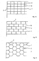
- FIG. 1a to 1c show top views in the manner of a grid or grids formed forms.
- the forms exist each from a large number of similar individual forms E, that of partly common longitudinal 1 and transverse walls 2 enclosed are.
- the shapes shown are each encircling Boundary wall 3 bordered.
- the boundary wall 3 can also be curved.
- Fig. 1a The shape shown in Fig. 1a is used to manufacture one rectangular shaped stones formed plaster, in which the Shaped stones are arranged without offset.
- the one shown in Fig. 1b Form is used to make a plaster in which the stones are staggered.
- Plaster is suitable for the form shown in Fig. 1c.
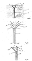
- FIG. 2a again shows a detailed view according to FIG. 1a.
- the Longitudinal 1 and transverse walls 2 are made of corrugated cardboard.
- the longitudinal and transverse walls 2 can also made of other, preferably rotten, material his. It is e.g. conceivable, the form of cardboard, polyethylene or the like.
- FIG. 2b shows a schematic sectional view accordingly the section line A - A 'in Fig. 2a, but here the Mold with a potting compound, e.g. Concrete or the like, poured is.
- the transverse wall 2 is made of corrugated cardboard. she is double-walled. There is a cavity between the walls H formed.
- the bend 4 is in cross-section like a triangle, in particular in the manner of an isosceles triangle.
- the peel surface 5 is used when peeling the encapsulated form as a guide surface for guiding a peel stick.
- FIG. 2c again shows a sectional view along the section line A - A 'in Fig. 2a.
- the wall of the bend 4 forming the peeling surface 5 can also be used be provided with a perforation 7.
- the perforation 7 enables tearing off the wall forming the peeling surface 5 the potting and the at least partial curing of the potting compound.
- FIG. 2d shows a schematic sectional view according to FIG Section line B - B 'in Fig. 2a.
- the bend is 4 executed like a triangle. Again, it's a parallel to the opening area O (not shown here) Peeling surface 5 is provided.
- the transverse wall 2 is off made of an easily decomposable material like corrugated cardboard.
- Towards the opening surface O (not shown here) first edge is a plastic profile made of polyethylene P attached.
- the plastic profile P has one Cavity H and a peeling surface similar to FIGS. 2b to 2d 5 on.
- the plastic profile P is after solidification the casting compound removed. Sand remains in the remaining joint has returned.
- the transverse wall 2 rots.
- the plastic profile P can be used multiple times. It can go without saying can also be attached to the longitudinal wall 1.
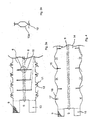
- FIG. 3a shows a sectional pattern of a first surface element 8.
- the first surface element 8 is made of corrugated cardboard. Crest lines 9 of the corrugation of the corrugated cardboard run vertically to the crease lines or creases 6. Parallel to the Creasing lines 6 can also be a pull-out thread (not shown here) run. The pull-out thread is conveniently in the material is incorporated and runs along the line of symmetry S of the first surface element 8. Parallel to the alignment the apex lines 9 are slit-like Recesses 10, each in the area of the crease lines 6 have a further recess 10a, which is in the form of a long straight hexagon is formed. The further recess 10a is shown again in detail in FIG. 3b.
- first floor insertion tabs 11 Extending from the long sides of the first surface element 8 first floor insertion tabs 11. You can first Have openings 12. Two first insertion tabs 13 extend from the transverse sides of the first surface element 8th.
- a second surface element 14 is shown in FIG. 4.
- the bend 4 also has the second surface element 14 crease lines 6 running parallel to the symmetry line S. on.
- Second slit-like ones extend from the long sides Recesses 15 in the direction of the crease lines 6.
- the apex lines the corrugation here also runs perpendicular to the crease lines 6.
- second floor insertion tabs 16 From the long sides of the second surface element 14 extend second floor insertion tabs 16, which expediently provided with a second opening 17 are.
- At 18 there are two extending from the transverse sides designated second insertion tabs.
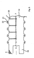
- the fifth is a sectional pattern of a third surface element 19 shown.
- the third surface element 19 is used for production the boundary wall 3.
- the crease lines 6 for production the bend shown in Fig. 2d run parallel to the line of symmetry S.
- Third slot-like recesses 20 up to the crease lines 6.
- the corrugation 9 is also perpendicular here the crease lines 7.
- Floor insertion tabs 21 are provided in the third openings 22 could be.
- two third insertion tabs 23 can also have corresponding perforations (not shown here) may be provided.
- the third slot-like recesses 20 can in this case Cutting out a strip from the third surface element 19 are manufactured.
- the educated third slot-like recesses 20 allow one oblique fastening of the peripheral boundary wall 3.
- Fig. 5a shows a plan view of a floor strip 24, the expediently made of easily decomposable material, such as corrugated cardboard, is made. Fourth slit-like openings 25 are used to insert the bottom insertion tabs 11 and 16. A load applied to the longitudinal 1 or transverse walls 2 removed on the ground strips 24 on the ground. In order to is a sinking of the longitudinal 1 or transverse walls 2 in the Avoid underground.
- the form according to the invention is in this Case walkable.
- Two boundary walls are used to produce the shape shown in FIG. 2a 3 required.
- a first boundary wall 3 are the third slot-like recesses 20 in one first distance and at a second boundary wall 3 are the third slot-like recesses 20 in one second distance arranged. If a boundary wall is provided with perforations provided at suitable intervals can the third slot-like recesses 20 each with a suitable distance.
- the longitudinal walls 1 are first shaped by folding of the first surface element 8 is produced around the crease lines 7.
- the second surface element is used to produce the transverse walls 2 14 in a similar manner to the first surface element 8 folded around the crease lines 6.
- the transverse walls 2 with the second slot-like recesses 15 in the first slot-like recesses 10 of the longitudinal walls 1 inserted.
- a grid-like grid is formed a variety of individual shapes with surrounding walls.
- the insertion tabs 13, 18 in the third slot-like recesses of the third surface element 19 inserted and bent. Then that will third surface element folded around the crease lines 6.
- On this way can easily be made from at least three surface elements produced the grating-like shape shown in Fig. 1a become.
- anchor elements pushed through the openings become.
- the anchor elements are expediently made of a rotten organic material. It can are rods made of wood, cardboard or cardboard.
- Figs. 1b and 1c can are made in a similar manner. Starting from the the pattern described here is in the manual Can make appropriate sewing patterns for making the in Fig. 1b and 1c indicate shapes shown.
- the longitudinal and transverse walls 2 can also be made without folds Corrugated cardboard.
- the bend 4 can in this Case by providing the plastic profile P (see Fig. 2e) will be realized.
- This embodiment is particularly simple and inexpensive.
- the plastic profiles P are recyclable. The shape can be built up relatively quickly.
- the plastic profiles P be provided with predetermined breaking points so that they can be used without tools can be cut to length as required.
- the invention also provides only molds for the production of individual stones provide. Such shapes can be much easier be formed. You can e.g. from a single surface element be produced that forms a circumferential wall. Corresponding to fix the surrounding wall latchable insert tabs may be provided.
- a patch For the manufacture of a patch, e.g. the previously in detail Described grid-like shape shown in FIG. 1a be taken.
- the shape is first with the bottom insert tabs 11, 16 and 21 inserted into the underground. Thereby prevents the shape from e.g. by wind in their Location is moved.
- For making a larger patch can have several of the grating-like designs according to the invention Forms placed side by side and in the underground be plugged in. Then the individual forms E Sealing compound, e.g. Concrete, poured. Expediently concrete used as casting compound.
- the surface element can be used to improve the durability of the mold 8, 14 and 19 with one or two sides be provided with a water-repellent coating. It can are a water-repellent biodegradable Act paint. Other slowly water-soluble substances are also suitable for producing such a coating.
Landscapes
- Engineering & Computer Science (AREA)
- Manufacturing & Machinery (AREA)
- Chemical & Material Sciences (AREA)
- Ceramic Engineering (AREA)
- Mechanical Engineering (AREA)
- Architecture (AREA)
- Civil Engineering (AREA)
- Structural Engineering (AREA)
- Moulds, Cores, Or Mandrels (AREA)
Applications Claiming Priority (4)
| Application Number | Priority Date | Filing Date | Title |
|---|---|---|---|
| DE2001162665 DE10162665B4 (de) | 2001-12-19 | 2001-12-19 | Form zur Herstellung eines mit Bindemittel gebundenen Formsteins und Verfahren zur Herstellung eines daraus hergestellter Pflaster |
| DE10162665 | 2001-12-19 | ||
| DE10236309 | 2002-08-08 | ||
| DE2002136309 DE10236309A1 (de) | 2002-08-08 | 2002-08-08 | Form und Verfahren zur Herstellung eines Formsteins und daraus hergestellter Pflaster |
Publications (1)
| Publication Number | Publication Date |
|---|---|
| EP1321579A1 true EP1321579A1 (fr) | 2003-06-25 |
Family
ID=26010812
Family Applications (1)
| Application Number | Title | Priority Date | Filing Date |
|---|---|---|---|
| EP02028339A Withdrawn EP1321579A1 (fr) | 2001-12-19 | 2002-12-17 | Coffrage de revêtement de sol et procédé pour la construction d'un tel revêtement de sol |
Country Status (1)
| Country | Link |
|---|---|
| EP (1) | EP1321579A1 (fr) |
Cited By (2)
| Publication number | Priority date | Publication date | Assignee | Title |
|---|---|---|---|---|
| EP1380690A1 (fr) * | 2002-07-12 | 2004-01-14 | Martin Bucknell | Coffrage de revêtement de sol et procédé pour la construction d'un tel revêtement de sol |
| DE102007046238A1 (de) * | 2007-09-26 | 2009-04-02 | Sf-Kooperation Gmbh Beton-Konzepte | Formstein aus Beton zur Verlegung von Erdreichabdeckungen und Bausatz aus derartigen Formsteinen |
Citations (7)
| Publication number | Priority date | Publication date | Assignee | Title |
|---|---|---|---|---|
| BE336255A (fr) * | ||||
| US2299318A (en) * | 1940-01-06 | 1942-10-20 | George W Forsberg | Form for paving blocks |
| US2368502A (en) * | 1942-11-09 | 1945-01-30 | Arthur E Troiel | Form for casting blocks |
| GB2129468A (en) * | 1982-11-04 | 1984-05-16 | Frank James Johnson | Concrete paving |
| US5450699A (en) * | 1993-12-23 | 1995-09-19 | Lee; Nam-Seung | Flexible partitioning member for use in forming concrete slab |
| US5636485A (en) * | 1991-10-05 | 1997-06-10 | Al-Saleh; Abdul A. A. | Tiling networks with geometrical and ornamental patterns |
| DE20105459U1 (de) * | 2001-03-28 | 2001-06-13 | Altmann, Michael, 51580 Reichshof | Formwerkzeug zum Formen von Gehplatten |
-
2002
- 2002-12-17 EP EP02028339A patent/EP1321579A1/fr not_active Withdrawn
Patent Citations (7)
| Publication number | Priority date | Publication date | Assignee | Title |
|---|---|---|---|---|
| BE336255A (fr) * | ||||
| US2299318A (en) * | 1940-01-06 | 1942-10-20 | George W Forsberg | Form for paving blocks |
| US2368502A (en) * | 1942-11-09 | 1945-01-30 | Arthur E Troiel | Form for casting blocks |
| GB2129468A (en) * | 1982-11-04 | 1984-05-16 | Frank James Johnson | Concrete paving |
| US5636485A (en) * | 1991-10-05 | 1997-06-10 | Al-Saleh; Abdul A. A. | Tiling networks with geometrical and ornamental patterns |
| US5450699A (en) * | 1993-12-23 | 1995-09-19 | Lee; Nam-Seung | Flexible partitioning member for use in forming concrete slab |
| DE20105459U1 (de) * | 2001-03-28 | 2001-06-13 | Altmann, Michael, 51580 Reichshof | Formwerkzeug zum Formen von Gehplatten |
Cited By (3)
| Publication number | Priority date | Publication date | Assignee | Title |
|---|---|---|---|---|
| EP1380690A1 (fr) * | 2002-07-12 | 2004-01-14 | Martin Bucknell | Coffrage de revêtement de sol et procédé pour la construction d'un tel revêtement de sol |
| GB2390631B (en) * | 2002-07-12 | 2005-10-26 | Martin Bucknell | Improved paving system |
| DE102007046238A1 (de) * | 2007-09-26 | 2009-04-02 | Sf-Kooperation Gmbh Beton-Konzepte | Formstein aus Beton zur Verlegung von Erdreichabdeckungen und Bausatz aus derartigen Formsteinen |
Similar Documents
| Publication | Publication Date | Title |
|---|---|---|
| DE3853418T2 (de) | Rahmen zum formen von fussbodenziegeln. | |
| DE60222569T2 (de) | Sechseckiges Pflasterelement | |
| EP0576939B1 (fr) | Elément de construction à usage multiple en plastique | |
| DE69930925T2 (de) | Verbesserte taktile indikatoren für sehbehinderte personen und dazugehörige installationsmethode | |
| DE3016963A1 (de) | Einsetz-baustein fuer gebaeudewaende und verfahren zum konstruieren von gebaeuden unter verwendung derartiger bausteine | |
| EP0026803B1 (fr) | Dispositif de coffrage avec une plaque en faux-oeuvre et des armatures en attente | |
| DE10018212A1 (de) | Verfahren und Vorrichtung zur Herstellung von biegesteifen Beton- Trägerelementen | |
| EP0617182A1 (fr) | Baguette multifonctionelle en plastique | |
| DE10236309A1 (de) | Form und Verfahren zur Herstellung eines Formsteins und daraus hergestellter Pflaster | |
| DE10162665B4 (de) | Form zur Herstellung eines mit Bindemittel gebundenen Formsteins und Verfahren zur Herstellung eines daraus hergestellter Pflaster | |
| DE19543908A1 (de) | Formstein | |
| DE29703008U1 (de) | Betonformstein für Bruchsteinmauern | |
| CH718328A2 (de) | Abschalleiste, Überdeckungsabschalung, Abschalungselement, Schalungsanordnung, Verfahren zum Aufbau einer Schalungsanordnung und Verfahren zum Herstellen einer Abschalleiste. | |
| EP0891446A1 (fr) | Dispositif auxiliaire pour poser notamment des agglomeres de beton | |
| EP3865623A1 (fr) | Profil d'assemblage | |
| WO2001059231A1 (fr) | Ecarteur | |
| DE19747770A1 (de) | Verfahren und Vorrichtung zum Herstellen von Betonsteinen, sowie danach bzw. damit hergestellte Betonsteine | |
| DE102010034600B4 (de) | Randbegrenzungsbord | |
| DE2063419C2 (de) | Verfahren und Form zum Herstellen einer Bodenbefestigung aus Beton, insbesondere für Verkehrswege | |
| DE3047116A1 (de) | Abstandshalter fuer stahlbetonbewehrungen sowie verfahren zur herstellung solcher abstandshalter | |
| EP0586867A1 (fr) | Coffrage d'about | |
| DE1916918C (de) | Verfahren zum Herstellen nivellierter Oberflachen und Vorrichtung zur Durchfuhrung des Verfahrens | |
| EP4063589A1 (fr) | Élément de coffrage pour une construction en béton | |
| DE7920890U1 (de) | Bauelement für Schallschutzwände | |
| WO2000036221A1 (fr) | Procede de fabrication d'un revetement de route en beton a l'aide de goujons |
Legal Events
| Date | Code | Title | Description |
|---|---|---|---|
| PUAI | Public reference made under article 153(3) epc to a published international application that has entered the european phase |
Free format text: ORIGINAL CODE: 0009012 |
|
| AK | Designated contracting states |
Designated state(s): AT BE BG CH CY CZ DE DK EE ES FI FR GB GR IE IT LI LU MC NL PT SE SI SK TR |
|
| AX | Request for extension of the european patent |
Extension state: AL LT LV MK RO |
|
| 17P | Request for examination filed |
Effective date: 20031213 |
|
| AKX | Designation fees paid |
Designated state(s): AT BE BG CH CY CZ DE DK EE ES FI FR GB GR IE IT LI LU MC NL PT SE SI SK TR |
|
| STAA | Information on the status of an ep patent application or granted ep patent |
Free format text: STATUS: THE APPLICATION IS DEEMED TO BE WITHDRAWN |
|
| 18D | Application deemed to be withdrawn |
Effective date: 20050701 |